Article

A Design-Oriented Combined Model (7 MPa to 190 MPa) for FRP-Confined Circular Short Columns

by
Zehra Canan Girgin
1,* and
Konuralp Girgin
2
1
Structural Systems Division, Architecture Faculty, Yildiz Technical University, Istanbul 34349, Turkey
2
Civil Engineering Faculty, Istanbul Technical University, Istanbul 34469, Turkey
*
Author to whom correspondence should be addressed.
Polymers 2015, 7(10), 1905-1917; https://doi.org/10.3390/polym7101489
Submission received: 3 August 2015 / Revised: 15 September 2015 / Accepted: 21 September 2015 / Published: 28 September 2015
(This article belongs to the Collection Fiber-Reinforced Polymer Composites in Structural Engineering)

Abstract

:
This study addresses a design oriented combined model to predict the ultimate strengths and ultimate strains in an extensive range of unconfined strength (7 to 190 MPa) for the axially loaded fiber-reinforced polymer (FRP)-wrapped circular short columns. Modified Hoek-Brown strength criterion, which was previously extended to FRP-confined concrete from 7 to 108 MPa, is revisited and verified. An empirical strength model beyond 108 MPa encompassing ultra-high strength concrete (UHSC) and ultra-high performance concrete (UHPC) data, as well as empirical strain models, are defined to accomplish the design oriented combined model. This article especially focuses on the verification of the proposed strain models. The assessment performances of those models for carbon FRP (CFRP) and glass FRP (GFRP) confinement are compared with specific models in the current literature. Strength and strain predictions for UHSC and UHPC are integrated into the design oriented combined model as well. The assessments on this model agree with the experimental results in high accuracy.

Graphical Abstract

1. Introduction

FRP composites have been used in the construction sector for over two decades due to their properties, such as high strength-to-weight ratio, high tensile strength and modulus, corrosion resistance, and durability. FRP confinement through a glass-fiber tube [1,2,3], frequently using carbon [4,5,6,7,8,9,10], sometimes aramid [11,12], and recently basalt [13], recycled plastic [12,14,15], and natural [16] fiber sheets were used in the experimental studies so far. In addition, the confinement with polypropylene ropes [17,18], FRP+steel tube [19], or prestressing at several levels [20] are recent material types and methods.
The experimental studies are often in the cylinder strength range of fco = 20–50 MPa [1,4,5,6,10]. Low strength data, under 20 MPa [4,5,8,21], and ultra-high strength concrete (UHSC) or ultra-high performance concrete (UHPC) data, over 100 MPa [22,23,24,25,26], are limited compared with the normal strength range (20 to 50 MPa). Increasing compressive strength levels in the construction sector enables to reduce member sizes. Higher confining pressure through an FRP jacket is required to prevent the inherent brittle behavior in UHSC or UHPC.
The Hoek-Brown criterion [27] enables to predict the tensile stresses in the compression-tension region contrary to the Mohr–Coulomb criterion. The Hoek-Brown criterion was initially extended and modified to actively confined concrete [28] and then to FRP-confined concrete [29]. The modified strength criterion for FRP confinement [29] was verified with the data from fco = 7 to 108 MPa. However, the data beyond 108 MPa was very limited to calibrate this model. In this study, a modified Hoek–Brown strength criterion is revisited exactly to define, especially, the upper strength ranges. The database was also updated (7 to 190 MPa) with new data covering UHSC and UHPC from the current literature. To complete the combined design oriented model, empirical and practical models with high accuracy are proposed for ultimate strengths and strains.

2. Strength and Strain Models for FRP Confinement

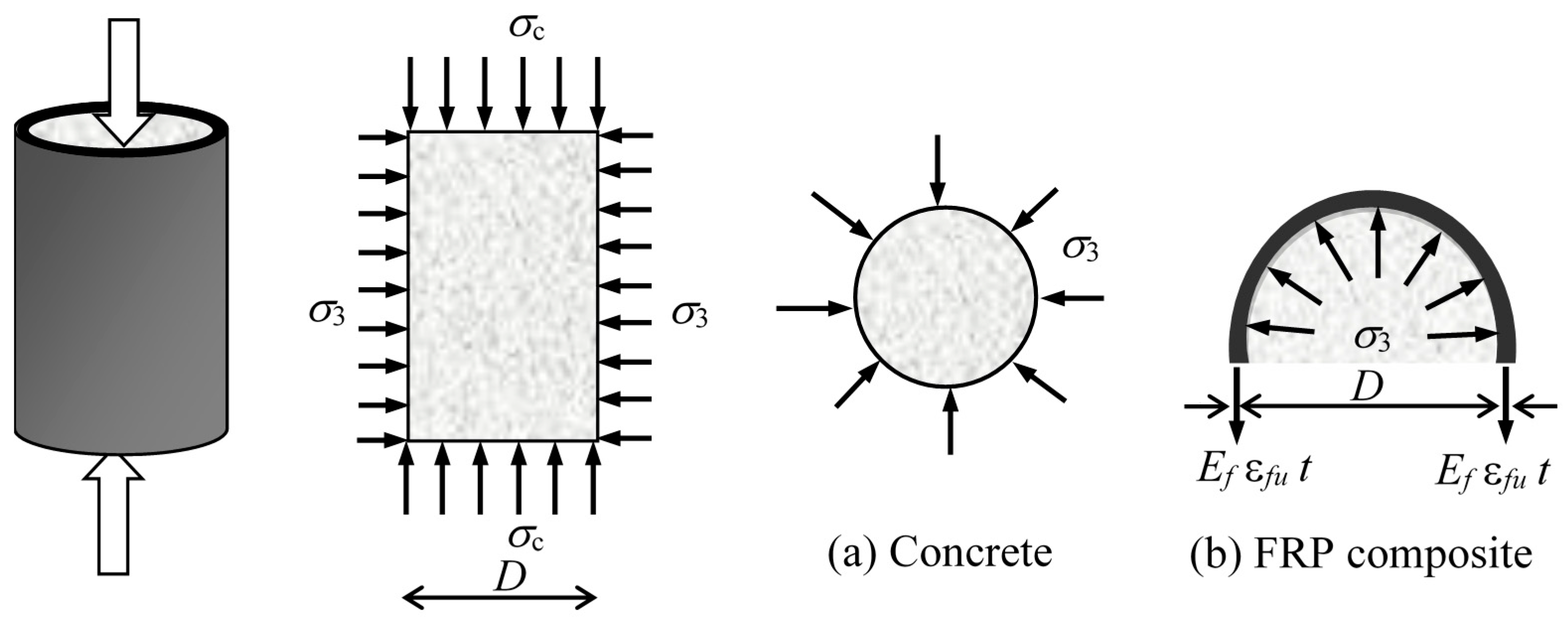
2.1. Confinement with FRP

Under triaxial compressive stresses, the columns are subjected to major compressive stresses (σ1) along the axial axis of the column and minor principal stresses (σ3, fl) enhancing the unconfined compressive strength of concrete (σc, fco) (Figure 1). Lateral passive confining pressure (fl) can be presently provided by FRP confinement (sheets and tubes) instead of steel confinement as well. fl can be expressed in terms of the ultimate fiber strain (εfu) and lateral modulus (El) of the FRP jacket:
f l = σ 3 = E l ε f u
where:
E l = 2 E f t D
or in terms of hoop tensile strength of FRP (σfrp or ffrp):
f l = 2 σ f r p t D
thus:
f l = 2 ​  E f ε f u t D = 1 2 ρ f E f ε f u ,   ρ f = 4 t D
where D, Ef, ρf, and t denote the diameter of concrete core, Young’s modulus, volumetric ratio, and thickness of FRP jacket, respectively.
Figure 1. Development of confining pressure in FRP confined concrete. (a) Confining pressure to concrete; (b) Ultimate confining pressure by FRP composite on concrete.
Polymers 07 01489 g001
FRP fiber strain (εfu) is generally based on coupon or manufacturer data, and is often smaller than actual hoop rupture strain (εh,u). While the relationships generally take coupon or manufacturer data into consideration, a few relationships [30,31,32] were also proposed in terms of actual confinement pressure (fl,a) and actual confinement ratio (fl,a/fco) through the hoop rupture strain (εh,u):
ε h , u = k ε , f ε f u
f l , a = 2 E f ε h , u t D
where kε,f signifies the strain reduction factor [33,34] smaller than one. In the literature, the average values of kε,f were determined to be 0.680, 0.793, 0.732 for CFRP, GFRP, and AFRP sheets, respectively [32]. It was realized that kε,f decreases as the unconfined compressive strength level increases, i.e., kε,f is 0.737, 0.656, 0.548 in normal, high, and ultra-high strength concrete confined with CFRP wraps, respectively [35]. Herein, it is noted that, to propose a relationship based on εh,u instead of εfu may be realistic, but it may not be proper for the practical assessment of ultimate strength.
In the literature, several strength models are available, however, the design oriented models predicting both stress and strain are more limited. Specific models to assess the ultimate strengths and strains in circular short columns are given in Table 1. It is mentioned that while fl/fco is higher than 0.07, fcc signifies the ultimate strength, otherwise denotes as the peak strength.
Stresses and strains will be verified through Integral Absolute Error (IAE), which was defined previously [28,29], and relative error or Average Absolute Error (AAE) in which:
IAE  ( % ) = | o i p i | o i × 100 ,  AAE  ( % ) = | ( o i p i ) / o i | × 100 n ,   ( o i = observed ,   p i = predicted )
Table 1. Strength and strain models in circular sections.
SourceStrength ModelStrain Model
Fardis and Khalili [2] strength model based on Richart et al. [36] (fco = 20–50 MPa) f c c f c o = 1 + 4.1 f l f c o ε c u = ε c o + 0.0005 E l f c o
Mander et al. [37] Saadatmanesh et al. [38] f c c f c o = 2.254 1 + 7.94 f l f c o 2 f l f c o 1.254 ε c u ε c o = 1 + 5    ( f c c f c o 1 )
ACI 440 [39] ε c u = 1.71 ( 5 f c c 4 f c o ) E c o
Karbhari and Gao [5] (fco = 38 MPa) f c c f c o = 1 + 2.1 ( f l f c o ) 0.87 Model II ε c u = ε c o + 0.01 f l f c o
Kono et al. [40] (fco = 32–35 MPa) f c c f c o = 1 + 0.0572 f l ε c u ε c o = 1 + 0.28 f l
Saafi et al. [41] (fco = 38 MPa) f c c f c o = 1 + 2.2 ( f l f c o ) 0.84 ε c u ε c o = 1 +    ( 537 ε f u + 2.6 ) ( f c c f c o 1 )
Spoelstra and Monti [33] (fco = 30–50 MPa) f c c f c o = 0.2 + 3 ( f l f c o ) 0.5 ε c u ε c o = 2 + 1.25 E c o f c o ε f u ( f l f c o ) 0.5 a
Xiao and Wu [42] (fco = 34–55 MPa, CFRP) f c c f c o = 1.1 + [ 4.1 0.75 ( f c o 2 / E l ) ] f l f c o ε c u = ε f u 0.0005 7 ( f c o / E l ) 0.8
Toutanji-modified [43] (fco = 31 MPa) f c c f c o = 1 + 2.3 ( f l f c o ) 0.85 ε c u ε c o = 1 +    ( 310.57 ε f u + 1.9 ) ( f c c f c o 1 )
Lam and Teng [30] (fco = 27–55 MPa) f c c f c o = 1 + 3.3 f l , a f c o    ( f l , a f c o 0.07 ) ε c u ε c o = 1.75 + 12 ( f l , a f c o )    ( ε h , u ε c o ) 0.45
ε c u ε c o = 1.92 + 24.45 f l , a f c o     ( C F R P )
ε c u ε c o = 1.75 + 5.53 ( f l f c o )     ( ε f u ε c o ) 0.45 ( C F R P )
Teng et al. [44] (fco = 38–46 MPa) f c c f c o = 1 + 3.5 ( ρ k 0.01 ) ρ ε    ( ρ k 0.01 )
ρ k = 2 E f t ε c o D f c o , ρ ε = 0.586 ε f u ε c o
ε c u ε c o = 1.75 + 6.5 ρ k 0.8 ρ ε 1.45
Benzaid et al. [31] (fco = 29–62 MPa, CFRP) f c c f c o = 1 + 1.6 f l f c o ,    f c c f c o = 1 + 2.2 f l , a f c o ε c u ε c o = 2 + 5.5 f l f c o ,    ε c u ε c o = 2 + 7.6 f l , a f c o
Rousakis et al. [45,46] (fco = 9–170 MPa) f c c f c o = 1 + ( ρ f E f f c o ) ( α E f 10 6 E f μ + β ) b ε c u ε c o = 1 + 24.8 4 E f t D f c o    ( 0.45 E f 10 6 E f μ + 0.0223 )    ( 40 E f t E f μ D ) 0.16
Ozbakkaloglu and Lim [32] f c c f c o = 1 + 3.64 f l , a f c o    ( C F R P ) ε c u ε c o = 2 + 17.41 f l , a f c o    ( C F R P )
f c c f c o = 1 + 2.64 f l , a f c o    ( G F R P ) ε c u ε c o = 2 + 24.47 f l , a f c o    ( G F R P )
a This model is focused in the Section 3.2; b Efµ = 10 MPa (for units compliance); α = −0.336, β = 0.0223 for FRP sheets ; α = −0.23, β = 0.0195 for FRP tube.

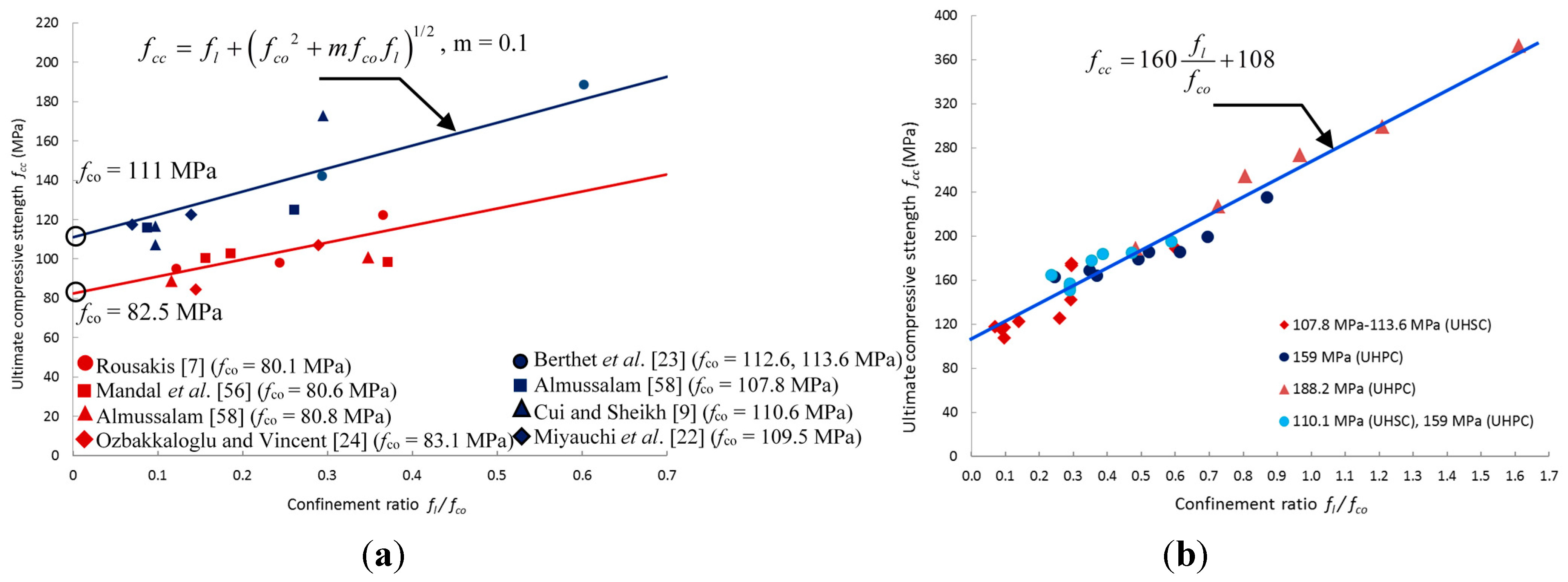
2.2. Strength Models

Earlier models for FRP confinement (Table 1) were proposed based on steel-confined concrete [2,36,37,38]. Most models [32,33,41,43] for steel and FRP-confined concrete are based on the Mohr–Coulomb criterion after Richart et al.’s pioneering investigation [36].
Hoek-Brown [27] and Johnston [47] strength criteria from rock mechanics were extended and modified [29,48] to precisely predict fcc in FRP-confined short columns from fco = 7 to 108 MPa. Data concerning different sheet types (Carbon, glass, aramid fiber, etc.) and GFRP tube (length-to-diameter ratio is about 2, low to high confinement ratios up to 2.0) were taken into consideration in two modified criteria (Table 2).
Table 2. Modified strength models from rock mechanics.
ReferenceFailure Criterion for RockModified Form for FRP Confined Concrete
Girgin [29]Hoek-Brown et al. [27]
σ 1 = σ 3 + σ c ( m σ 3 σ c + s ) 0.5
σ c ≥ 20 MPa
f c c = f l + ( s f c o 2 + m f c o f l ) 1 / 2
s = 1 for intact rock or undamaged concrete
m = 2.9 (fco = 7 to18 MPa)
m = 6.34−0.076 fco (fco = 20 to 82 MPa)
m = 0.1 (fco = 82 to 108 MPa)
Girgin [48]Johnston [47]
σ 1 σ c = ( 1 + M B . σ 3 σ c ) B
f c c f c o = ( 1 + M B . f l f c o ) B
B = 1 0.0172 ( log f c o ) 2 , fco in kPa
M = 0.0035 f c o 2 0.056 f c o + 2.83 (fco = 7 to 24 MPa)
M = 0.0003 f c o 2 0.076 f c o + 5.46 (fco = 25 to 108 MPa)
In this study, we hope to re-verify m coefficients of modified Hoek-Brown criterion and to also address higher compressive strength levels (fco > 108 MPa). The current database [1,4,5,6,7,8,11,12,21,22,23,41,42,49,50,51,52,53,54,55,56,57,58,59,60,61,62,63] composed of n = 198 averaged data was updated with n = 40 data [9,10,22,23,24,25,26,35,64] from the recent literature on HSC, UHSC, and UHPC for the FRP sheet types mentioned above. Meanwhile, UHSC and UHPC strength data in the literature are available up to 113.6 and 188 MPa, respectively.

2.3. Strain Models

The ultimate strain of confined concrete (εcu) is generally defined in terms of confining pressure, confinement ratio, strengthening ratio, and some additional parameters such as ultimate strain of FRP, initial elastic modulus and confinement modulus (fl, fl/fco, fl,a/fco, fcc/fco, εf, Eco, El).
ACI 440 [39], and Spoelstra and Monti [33] used the initial elastic modulus of concrete (Eco) in the suggested models (Table 1). Several formulas [65,66,67,68,69,70,71] to predict Eco were proposed in the current literature so far. Herein, fib MC2010 [70] was used in the assessment of these models. That model gives similar results to Noguchi et al.’s [69] model, which was performed for more than 3000 tests, for the limestone aggregates commonly used in concrete. Although fib MC2010 [70] model was originally defined up to 80 MPa, the model also matches with the test results of UHSC and UHPC [71] from 107 to 179 MPa. Thus, the model in Equation (8) was used from 20 to 190 MPa.
E c o = 21500    f c o 10 3
Strain models are often expressed in terms of strain enhancement (εcuco) or ductility. However, εco values are not always determined experimentally, and can usually be assumed to be 0.002 [5,10,32,42] or calculated according to some empirical relationships in the current literature. In this study, εco values were derived as per the following formula in Eurocode 2 [72]:
ε c o = 0.7 1000 f c o 0.31
Hoek-Brown failure criterion from rock mechanics [27] is a strength model. For this reason, in this study, combining strain models will be introduced for the most common types of FRP confinement. Thus, the database was mainly compiled with the experimental results of CFRP-wrapped specimens (n = 177) and more limited data of GFRP-wrapped specimens (n = 62). Meanwhile, higher scattering in ultimate strain data (εcu) is generally observed compared with those of ultimate strengths (fcc), and less data for strains are available in the current literature. Lower and upper limits of strength and strain data are not exactly the same due to some absent strain data. The lower limits of available strain data correspond to fco = 15 MPa (CFRP) and 18 MPa (GFRP). The upper limit of strength data is fco = 188 MPa. There are discontinuities (from 50 to 80 MPa) in the strength ranges of limited GFRP-wrapped specimens.

3. Results and Discussion

In this study, a design-oriented combined model is proposed to predict the ultimate strengths (fcc) and ultimate strains (εcu) in the axially loaded FRP-confined circular short columns. The upper limit (fco = 108 MPa) of the modified Hoek–Brown strength criterion [29] is revisited and verified. An empirical strength model encompassing UHSC and UHPC data up to fco = 190 MPa, as well as empirical strain models, are defined to accomplish the design-oriented combined model.

3.1. Ultimate Strength Prediction

In two previous studies [29,48], the performances of the specific strength models in the current literature were compared with the presented modified Hoek–Brown and Johnston strength criteria. These comparisons were conducted through IAE and AAE ratios with respect to the concerning strength ranges.
It was concluded that the strength models [2,36,37,38] based on steel confinement give rise to higher estimation than experimental ones in each relevant strength range known in the current literature [1,5,33,73]. While the prediction performance of some models are restricted concerning range [22], some of those models are also capable of reasonably predicting wider data ranges [5,33,41]. Specific strength models generally overestimate the ultimate strengths (fcc) for fco > 70 MPa [1,5,22,33,41,43,44,50,55] or for fco < 20 MPa [1,22,44], however, some models having a good accuracy for all the data ranges are also available [45]. Herein, the performance details of those strength models will not be mentioned again in detail.
IAE and AAE ratios of the proposed modified Hoek-Brown strength criterion [29], as well as modified Johnston strength criterion [48], are under 6% for each specific strength range. It should be mentioned that the prediction performance based on the ranges of cylinder strength (fco) may be more meaningful than the one error ratio (i.e., AAE, etc.) often used in the current literature.
In this study, the expressions of m coefficient (Table 2) in the modified Hoek–Brown strength criterion were not changed, m = 0.1 is valid from fco = 82 to 114 MPa according to the comparisons in this study (Figure 2a). However, for compressive strength levels over 114 MPa, only the m coefficient may not be sufficient for very satisfactory estimations; therefore, the following empirical relationship from fco = 108 to 190 MPa for fl/fco = 0 to 1.6 is asserted to assess the ultimate strength of circular short columns strengthened with CFRP, GFRP, and AFRP jackets:
f c c = 160 f l f c o + 108   ( n = 31 ,   R = 0.982 ,  IAE = 5.5 % ,  AAE = 5.7 % )
Equation (10) addresses UHSC data, as well as UHPC data [9,22,23,24,25,26,35], with high accuracy (Figure 2b).
Figure 2. (a) Verification of modified Hoek–Brown criterion for high and ultra-high compressive strength levels; (b) Proposed empirical model from fco = 108 to 190 MPa for UHSC and UHPC data of CFRP, GFRP, AFRP jackets.
Polymers 07 01489 g002

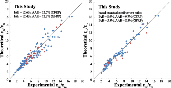
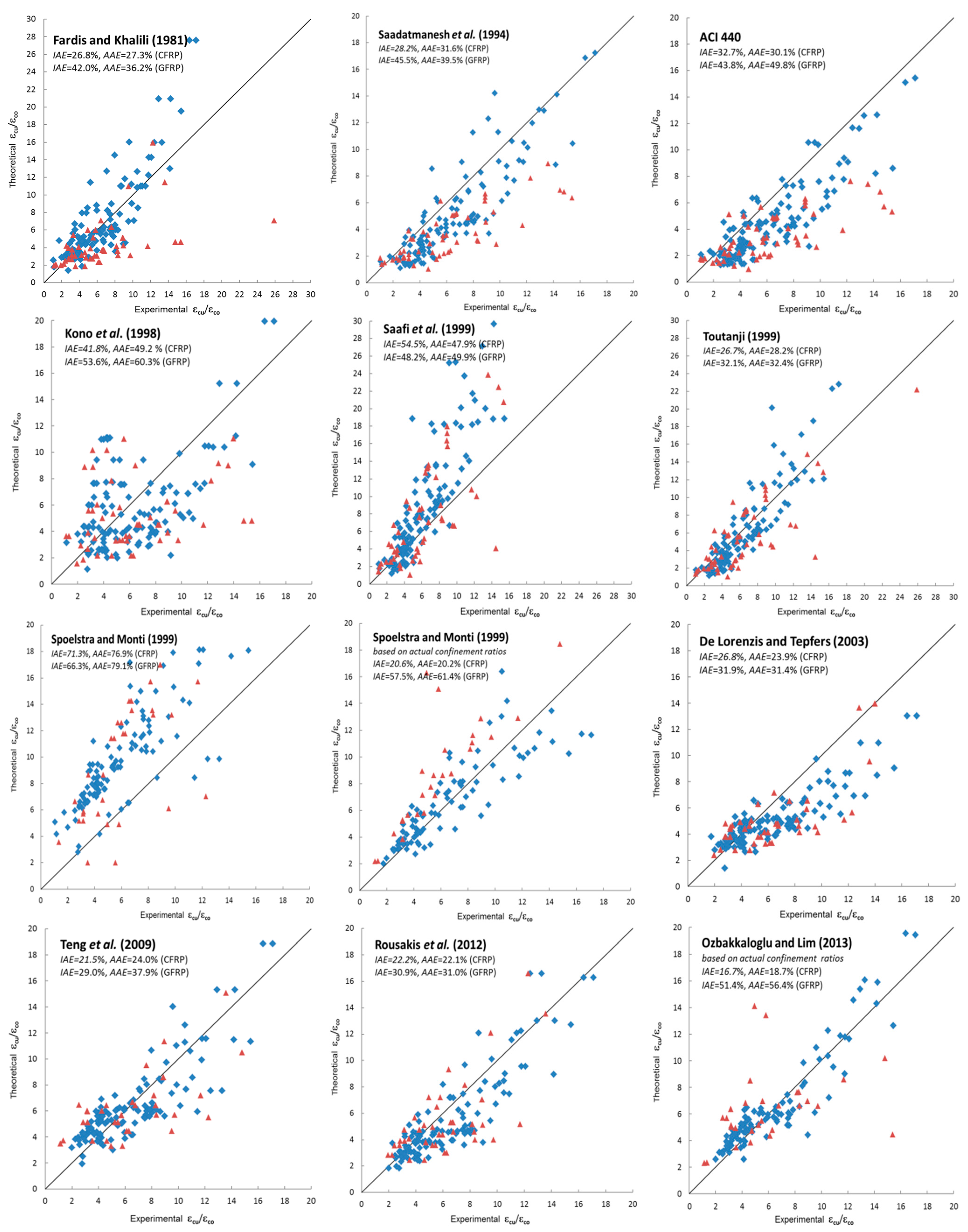
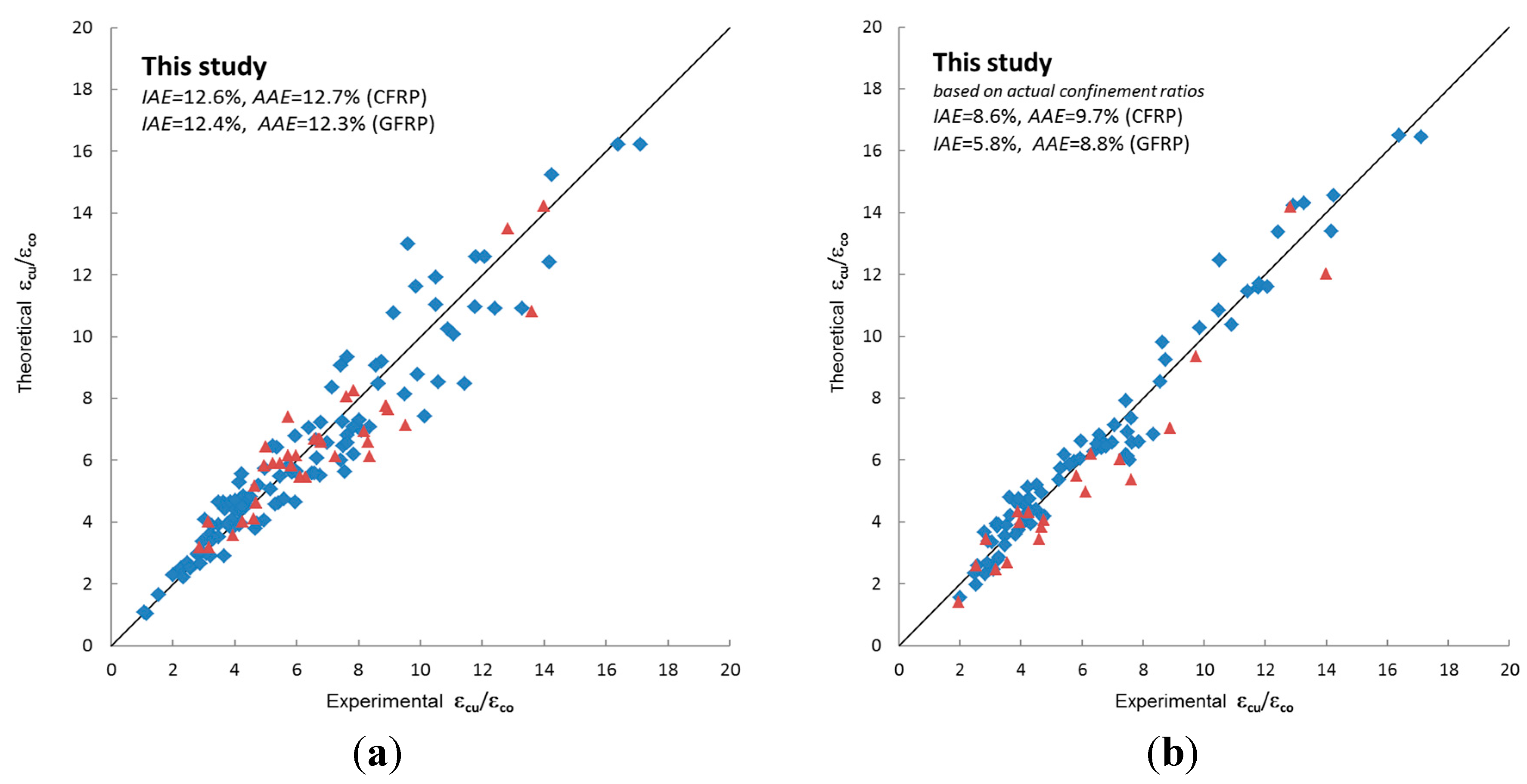
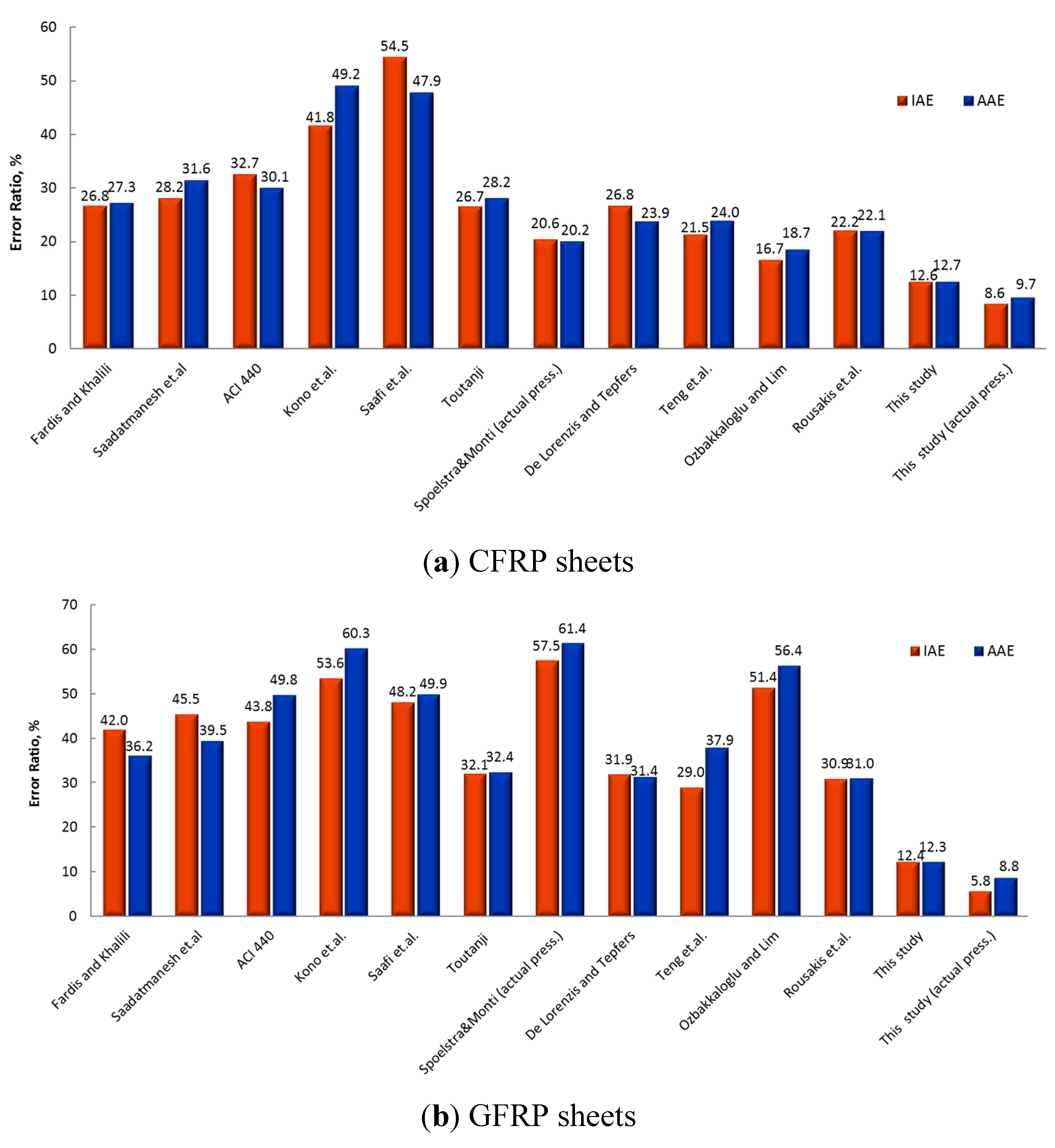
3.2. Ultimate Strain Prediction

The prediction capabilities of specific strain models [2,32,33,38,39,40,41,43,44,46,73] are investigated. Following this assessment, the empirical models of this study are introduced to predict the ultimate strains (εcu) with high accuracy. Meanwhile, strain values deviating significantly from the general trend were discarded from the analyses.
Figure 3 illustrates the performance charts of those specific strain models, via IAE and AAE ratios for CFRP and GFRP confinement. 45-degree line passing through the origin represents the perfect predictions of strains in the charts. The lower and upper parts of this line indicate conservative and unconservative strain estimations, respectively. The specific models [2,32,33,38,39,40,41,43,44,46,73] were investigated with regard to the range of database in this study. However, it should be mentioned that those models tend to significantly overestimate the strain capacity, at or over about fco = 100 MPa. Thus, the upper value of strain data was limited to fco = 110 MPa, except for the asserted strain models of this study. The models developed in this study reflect all the database.
Strain models by ACI 440 [39], and Spoelstra and Monti [33] contain the concrete initial elastic modulus (Eco). This parameter was defined in Equation (8). In the models based on εcu [2,5,39,42], those strains were converted to εcuco ratios, as per Equation (9). As seen from Figure 3, the earlier models, such as ACI 440 [39] and those of Saadatmanesh et al. [38] underestimate the strain enhancement (εcuco) due to FRP confinement, especially for GFRP-wrapped specimens. As fco increases, conservative predictions in Kono et al.’s model [40] lead to unsafe results in high confinement levels. Fardis and Khalili’s model [2] overestimates the strain enhancement for CFRP jackets, and underestimates those of GFRP jackets. The models by Saafi et al. [41], and De Lorenzis and Tepfers [73] are, respectively, characterized with a considerable overestimation and a substantial underestimation, increasing with the confinement ratio of CFRP and GFRP sheets. Toutanji’s model [43], compared to similar models, implies relatively proper values. If Spoelstra and Monti’s [33] model is implemented via actual confinement values (εh,u, fl,a) regarding [74], the model reveals sensitive predictions instead of significant overestimations for CFRP sheets. The evaluation results for two cases under consideration are also displayed in Figure 3. It should be mentioned that the model was referred to on the basis of εfu, fl in the previous studies [75].
This study also signifies an important point arising from error definitions, i.e., Integral Absolute Error (IAE) may be more sensitive than common Average Absolute Error (AAE). In AAE definitions, the difference between observed and predicted value is small for lower strength or strain values, otherwise the differences between higher values are also high. This case may reflect more unreliable verification results. Otherwise, as for IAE, the error definition based on the ratio of strength or strain differences may lead to a more accurate evaluation, by surpassing the differences due to lower or extreme values. The difference between AAE and IAE ratios may also be realized from Figure 3.
Figure 3. Accuracy of strain models in the current literature columns confined with CFRP and GFRP wraps (fco from 15 to 110 MPa, for CFRP sheets, for GFRP sheets).
Polymers 07 01489 g003
The strain models of this study were expressed and verified in detail (Table 3). These models were categorized in two groups (CFRP, GFRP) in terms of confinement ratios (fl/fco, fl,a/fco), as per unconfined strength (fco) ranges, to provide practical assessments. fco does not significantly affect the form of curve; however, two compressive strength levels (e.g., about 50 and 100 MPa for CFRP sheets) are realized from different data distributions. The definition range and curve of any model were achieved by taking this dissimilarity into consideration. Available UHSC and UHPC data are characterized through a linear form within the range of confinement ratio. Any relationship beyond fco = 170 MPa was not described due to the fact that there was only available one data set [25] and a continuously lowering slope. On the other hand, the strain model for actual confinement ratios (fl,a/fco) was attained in a wide range, from low strength up to about 100 MPa; however, εcu data is very limited beyond this.
Strain enhancements (εcuco) via these strain models may be assessed with high precision (Figure 4). The prediction performances of specific models (Table 1) and introduced strain models are compared in Figure 5.
Table 3. The strain models developed in this study and prediction capacity.
ParameterStrain ModelsRange of DatanIAE %AAE %Figures
Models for CFRP sheets
f l / f c o Ia ε c u ε c o = 2.77 ( f l f c o ) 2 + 12.67 ( f l f c o ) 0.061 f c o + 5.07 15 MPa ≤ fco ≤ 50 MPa a
0.11 ≤ fl/fco ≤ 1.78
10213.313.5-
Ib ε c u ε c o = 4.24 ( f l f c o ) 2 + 15.4 ( f l f c o ) + 2.23 15 MPa ≤ fco ≤ 50 MPa
0.11 ≤ fl/fco ≤ 1.78
10212.613.1Figure 4a
II ε c u ε c o = 2.62 ( f l f c o ) 2 + 10.94 ( f l f c o ) + 1.0 50 MPa < fco ≤ 103 MPa
0.12 ≤ fl/fco ≤ 0.58
4511.711.0
III ε c u ε c o = 0.57 ( f l f c o ) + 1.0 109 MPa <fco ≤ 170 MPa b
0.07 ≤ fl/fco ≤ 0.87
105.76.2
f l , a / f c o IV ε c u ε c o = 6 ( f l , a f c o ) 2 + 20.15 ( f l , a f c o ) 0.032 f c o + 3.5 20 MPa < fco ≤ 103 MPa
0.03 ≤ fl,a/fco ≤ 1.01
968.69.7Figure 4b
Models for GFRP sheets
f l / f c o V ε c u ε c o = 1.85 ( f l f c o ) 2 + 8.62 ( f l f c o ) + 4.4 18 MPa ≤ fco ≤ 50 MPa
0.09 ≤ fl/fco ≤ 2.0
3313.412.3Figure 4a
VI ε c u ε c o = 6.4 ( f l f c o ) 2 + 12.43 ( f l f c o ) + 0.9 80 MPa < fco ≤ 159 MPa
0.1≤ fl/fco ≤ 0.6
1011.912.3
f l , a / f c o VII ε c u ε c o = 2.03 ( f l , a f c o ) 2 + 10.41 ( f l , a f c o ) + 1.41 18 MPa ≤ fco ≤ 111 MPa
0.013 ≤ fl,a/fco ≤ 1.958
135.88.8Figure 4b
a The model is also valid up to fco = 85 MPa and fl/fco = 0.4 with 19.2% IAE and 21.0% AAE for 50–85 MPa range; b UHPC data was also included.
Figure 4. The assessment performance of proposed strain models for (a) predicted confinement ratio fl/fco based on ultimate fiber strain εfu from Model Ib, II, III, V,VI; (b) actual confinement ratio fl,a/fco based on εh,u from Model IV and VII, for CFRP sheets, for GFRP sheets.
Polymers 07 01489 g004
Figure 5. Error ratios of all the models under consideration for (a) CFRP sheets and (b) CFRP sheets.
Polymers 07 01489 g005

4. Conclusions

In this study, a design oriented combined model was developed to predict the ultimate strengths and ultimate strains in an extensive range of unconfined strength (7 to 190 MPa) for FRP-wrapped circular columns. The following results are drawn from this study:
(1) Modified Hoek–Brown strength criterion was revisited and the range of unconfined strength was extended to fco = 114 MPa.
(2) An empirical strength model with high precision was presented by encompassing UHSC and UHPC from fco = 108 to 190 MPa.
(3) Strain models were developed and expressed for CFRP, GFRP from fco = 15 to 170 MPa. It is realized that, when these models were compared with existing ones in the current literature, IAE and AAE ratios of produced strain models are very satisfactory.
(4) To evaluate the models, Integral Absolute Error (IAE) may be more sensitive than the Average Absolute Error (AAE) commonly used in the literature.
(5) This design-oriented combined model can be effectively used for predesign purposes or fast checks of solutions.
(6) Since the experimental strain data for GFRP sheets are relatively limited in the literature, the relevant model may be revisited in the future.

Author Contributions

Konuralp Girgin investigated and processed strain data; Zehra Canan Girgin investigated new strength data and carried out regression analyses and evaluated by graphics for strength and strain data; Zehra Canan Girgin and Konuralp Girgin discussed the results and prepared the manuscript.

Conflicts of Interests

The authors declare no conflict of interest.

References

  1. Samaan, M.; Mirmiran, A.; Shahawy, M. Modeling of concrete confined by fiber composites. J. Struct. Eng. 1998, 124, 1025–1031. [Google Scholar] [CrossRef]
  2. Fardis, M.N.; Khalili, H. Concrete encased in fiberglass-reinforced plastic. ACI Struct. J. 1981, 78, 440–445. [Google Scholar]
  3. Huang, L.; Sun, X.; Yan, L.; Zhu, D. Compressive behavior of concrete confined with GFRP tubes and steel spirals. Polymers 2015, 7, 851–875. [Google Scholar] [CrossRef]
  4. Howie, I.; Karbhari, V.M. Effect of Materials Architecture on Strengthening Efficiency of Composite Wraps for Deteriorating Columns in the North-East. In Infrastructure: New Materials and Methods of Repair; Basham, K.D., Ed.; American Society of Civil Engineers: New York, NY, USA, 1994; pp. 199–206. [Google Scholar]
  5. Karbhari, V.M.; Gao, Y. Composite jacketed concrete under uniaxial compression-verification of simple design equations. J. Mater. Civ. Eng. 1997, 9, 185–193. [Google Scholar] [CrossRef]
  6. Watanabe, K.; Nakamura, H.; Honda, T.; Toyoshima, M.; Iso, M.; Fujimaki, T.; Kaneto, M.; Shirai, N. Confinement Effect of FRP Sheet on Strength and Ductility of Concrete Cylinders under Uniaxial Compression. In Proceedings of the 3rd International Symposium on Non-Metallic (FRP) Reinforcement for Concrete Structure, Sapporo, Japan, 14–16 October 1997; pp. 233–240.
  7. Rousakis, T. Experimental Investigation of Concrete Cylinders Confined by Carbon FRP Sheets, under Monotonic and Cyclic Axial Compressive Load; Chalmers University of Technology: Göteborg, Sweden, 2001; p. 87. [Google Scholar]
  8. Ilki, A.; Peker, O.; Karamuk, E.; Demir, C.; Kumbasar, N. FRP retrofit of low and medium strength circular and rectangular reinforced concrete columns. J. Mater. Civ. Eng. 2008, 20, 169–188. [Google Scholar] [CrossRef]
  9. Cui, C.; Sheikh, S.A. Experimental study of normal- and high-strength concrete confined with fiber-reinforced polymers. J. Compos. Constr. 2010, 14, 553–561. [Google Scholar] [CrossRef]
  10. Song, X.; Gu, X.; Li, Y.; Chen, T.; Zhang, W. Mechanical behavior of FRP-strengthened concrete columns subjected to concentric and eccentric compression loading. J. Compos. Constr. 2013, 17, 336–346. [Google Scholar] [CrossRef]
  11. Rochette, P.; Labossière, P. Axial testing of rectangular column models confined with composites. J. Compos. Constr. 2000, 4, 129–136. [Google Scholar] [CrossRef]
  12. Dai, J.G.; Bai, Y.L.; Teng, J.G. Behaviour and modeling of concrete confined with FRP composites of large deformability. J. Compos. Constr. 2011, 15, 963–973. [Google Scholar] [CrossRef]
  13. Campione, G.; La Mendola, L.; Monaco, A.; Valenza, A.; Fiore, V. Behavior in compression of concrete cylinders externally wrapped with basalt fibers. Compos. Part B 2015, 69, 576–586. [Google Scholar] [CrossRef]
  14. Bai, Y.L.; Dai, J.G.; Teng, J.G. Cyclic compressive behavior of concrete confined with large rupture strain FRP composites. J. Compos. Constr. 2014, 18, 04013025. [Google Scholar] [CrossRef]
  15. Ispir, M. Monotonic and cyclic compression tests on concrete confined with PET-FRP. J. Compos. Constr. 2014, 19, 04014034. [Google Scholar] [CrossRef]
  16. Yan, L. Plain concrete cylinders and beams externally strengthened with natural flax fabric reinforced epoxy composites. Mater. Struct. 2015. [Google Scholar] [CrossRef]
  17. Rousakis, T. Hybrid confinement of concrete by FRP sheets and fiber ropes under cyclic axial compressive loading. J. Compos. Constr. 2013, 17, 732–743. [Google Scholar] [CrossRef]
  18. Rousakis, T.C.; Tourtouras, I.S. RC columns of square section-passive and active confinement with composite ropes. Compos. Part B 2014, 58, 573–581. [Google Scholar] [CrossRef]
  19. Feng, P.; Cheng, S.; Bai, Y.; Ye, L. Mechanical behavior of concrete-filled square steel tube with FRP-confined concrete core subjected to axial compression. Compos. Struct. 2015, 123, 312–324. [Google Scholar] [CrossRef]
  20. Vincent, T.; Ozbakkaloglu, T. Compressive behavior of prestressed high-strength concrete-filled aramid FRP tube columns: Experimental observations. J. Compos. Constr. 2015. [Google Scholar] [CrossRef]
  21. Pon, T.H.; Li, Y.F.; Shih, B.J.; Han, M.S.; Chu, G.D.; Chiu, Y.J. Experiments of Scale Effects on the Strength of FRP Reinforced Concrete. In Proceedings of the 4th National Conference on Structural Engineering, Taipei, China, September 1998; pp. 2133–2140.
  22. Miyauchi, K.; Inoue, S.; Kuroda, T.; Kobayashi, A. Strengthening effects of concrete columns with carbon fiber sheet. Trans. Jpn. Concr. Inst. 1999, 21, 143–150. [Google Scholar]
  23. Berthet, J.F.; Ferrier, E.; Hamelin, P. Compressive behavior of concrete externally confined by composite jackets. Part A: Experimental study. Constr. Build. Mater. 2005, 19, 223–232. [Google Scholar] [CrossRef]
  24. Ozbakkaloglu, T.; Vincent, T. Axial compressive behavior of circular high-strength concrete-filled FRP tubes. J. Compos. Constr. 2013, 18, 1–11. [Google Scholar] [CrossRef]
  25. Zohrevand, P.; Mirmiran, A. Behavior of ultra high-performance concrete confined by fiber-reinforced polymers. J. Mater. Civ. Eng. 2011, 23, 1727–1734. [Google Scholar] [CrossRef]
  26. Guler, S.; Copur, A.; Aydogan, M. Nonlinear finite element modeling of FRP-wrapped UHPC columns. Comput. Concr. 2013, 12, 413–429. [Google Scholar] [CrossRef]
  27. Hoek, E.; Kaiser, P.K.; Bawden, W.F. Support of Underground Excavations in Hard Rock; Balkema, A.A., Ed.; CRC Press: Rotterdam, The Netherlands, 1995; p. 215. [Google Scholar]
  28. Girgin, Z.C.; Arıoglu, N.; Arıoglu, E. Evaluation of strength criteria for very-high-strength concretes under triaxial compression. ACI Struct. J. 2007, 104, 278–284. [Google Scholar]
  29. Girgin, Z.C. A modified failure criterion to predict ultimate strength of circular columns confined by different materials. ACI Struct. J. 2009, 106, 800–809. [Google Scholar]
  30. Lam, L.; Teng, J.G. Design-oriented stress-strain model for FRP-confined concrete. Constr. Build. Mater. 2003, 17, 471–489. [Google Scholar] [CrossRef]
  31. Benzaid, R.; Mesbah, H.; Chikh, N. FRP-confined concrete cylinders: Axial compression experiments and strength model. J. Reinf. Plast. Compos. 2010, 29, 2469–2488. [Google Scholar] [CrossRef]
  32. Ozbakkaloglu, T.; Lim, J.C. Axial compressive behavior of FRP-confined concrete: Experimental test database and a new design-oriented model. Compos. Part B 2013, 55, 607–634. [Google Scholar] [CrossRef] [Green Version]
  33. Spoelstra, M.R.; Monti, G. FRP-confined concrete model. J. Compos. Constr. 1999, 3, 143–150. [Google Scholar] [CrossRef]
  34. Pessiki, S.; Harries, K.A.; Kestner, J.; Sause, R.; Ricles, J.M. The axial behavior of concrete confined with fiber reinforced composite jackets. J. Compos. Constr. 2001, 5, 237–245. [Google Scholar] [CrossRef]
  35. Vincent, T.; Ozbakkaloglu, T. Influence of concrete strength and confinement method on axial compressive behavior of FRP confined high- and ultra-high-strength concrete. Compos. Part B 2013, 50, 413–428. [Google Scholar] [CrossRef]
  36. Richart, E.; Brandtzaeg, A.; Brown, R.L. Failure of Plain and Spirally Reinforced Concrete in Compression; University of Illinois, Engineering Experimental Station: Champaign, IL, USA, 1929; Volume 190. [Google Scholar]
  37. Mander, J.B.; Priestley, J.N.; Park, R. Theoretical stress-strain model for confined concrete. J. Struct. Eng. 1988, 114, 1804–1826. [Google Scholar] [CrossRef]
  38. Saadatmanesh, H.; Ehsani, M.R.; Li, M.W. Strength and ductility of concrete columns externally reinforced with fiber composite straps. ACI Struct. J. 1994, 91, 434–447. [Google Scholar]
  39. Guide for the Design and Construction of Externally Bonded FRP Systems for Strengthening Concrete Structures; ACI 440.2R-08; American Concrete Institute (ACI) Committee: Farmington Hills, MI, USA, 2008.
  40. Kono, S.; Inazuni, M.; Kaku, T. Evaluation of Confining Effects of CFRP Sheets on Reinforced Concrete Members. In Proceedings of the 2nd International Conference on Composites in Infrastructure, Tucson, AZ, USA, 5–7 January 1998.
  41. Saafi, M.; Toutanji, H.A.; Li, Z. Behaviour of concrete columns confined with fiber reinforced polymer tubes. ACI Mater. J. 1999, 96, 500–509. [Google Scholar]
  42. Xiao, Y.; Wu, H. Compressive behavior of concrete confined by carbon fiber composite jackets. J. Mater. Civ. Eng. 2000, 12, 139–146. [Google Scholar] [CrossRef]
  43. Toutanji, H.A. Stress-strain characteristics of concrete columns externally confined with advanced fibre composite sheets. ACI Mater. J. 1999, 96, 397–402. [Google Scholar]
  44. Teng, J.; Jiang, T.; Lam, L.; Luo, Y. Refinement of a design-oriented stress–strain model for FRP-confined concrete. J. Compos. Constr. 2009, 13, 269–278. [Google Scholar] [CrossRef]
  45. Rousakis, T.C.; Rakitzis, T.D.; Karabinis, A.I. Design-oriented strength model for FRP-confined concrete members. J. Compos. Constr. 2012, 16, 615–625. [Google Scholar] [CrossRef]
  46. Rousakis, T.; Rakitzis, T.; Karabinis, A. Empirical Modelling of Failure Strains of Uniformly FRP Confined Concrete Columns. In Proceedings of the 6th International Conference on FRP Composites in Civil Engineering (CICE), Rome, Italy, 13–15 June 2012.
  47. Johnston, I.W. Comparison of two strength crieria for intact rock. J. Geotech. Eng. Div. 1985, 111, 1449–1454. [Google Scholar] [CrossRef]
  48. Girgin, Z.C. Modified Johnston failure criterion from rock mechanics to predict the ultimate strength of fiber reinforced polymer (FRP) confined columns. Polymers 2014, 6, 59–75. [Google Scholar] [CrossRef]
  49. Mirmiran, A.; Shahawy, M. Behavior of concrete columns confined by fiber composites. J. Struct. Eng. 1997, 123, 583–590. [Google Scholar] [CrossRef]
  50. Thériault, M.; Neale, K.W. Design equations for axially loaded reinforced concrete columns strengthened with FRP wraps. Can. J. Civ. Eng. 2000, 27, 1011–1020. [Google Scholar] [CrossRef]
  51. Karabinis, A.I.; Rousakis, T.C. Concrete confined by FRP material: A plasticity approach. Eng. Struct. 2002, 24, 923–932. [Google Scholar] [CrossRef]
  52. Lin, C.; Li, Y. An effective peak stress formula for concrete confined with carbon fibre reinforced plastics. Can. J. Civ. Eng. 2003, 30, 882–889. [Google Scholar] [CrossRef]
  53. Lin, H.L.; Liao, C.I. Compressive strength of reinforced concrete-column confined by composite materials. Compos. Struct. 2004, 65, 239–250. [Google Scholar] [CrossRef]
  54. Thériault, M.; Neale, K.W.; Claude, S. Fiber-reinforced polymer-confined circular concrete columns: Investigation of size and slenderness effects. J. Compos. Constr. 2004, 8, 323–331. [Google Scholar] [CrossRef]
  55. Lam, L.; Teng, J.G. Ultimate condition of FRP-confined concrete. J. Compos. Constr. 2004, 8, 539–548. [Google Scholar] [CrossRef]
  56. El Chabib, H.; Nehdi, M.; El Naggar, M.H. Behavior of SCC confined in short GFRP tubes. Cem. Concr. Compos. 2005, 27, 55–64. [Google Scholar] [CrossRef]
  57. Mandal, S.; Hoskin, A.; Fam, A. Influence of concrete strength on confinement effectiveness of fiber-reinforced polymer circular jackets. ACI Struct. J. 2005, 102, 383–392. [Google Scholar]
  58. Triantafillou, T.C.; Papanicolaou, C.G.; Zissimopoulos, P.; Laourdekis, T. Concrete confinement with textile-reinforced mortar jackets. ACI Struct. J. 2006, 103, 28–37. [Google Scholar]
  59. Almussalam, T.H. Behavior of normal and high-strength concrete cylinders confined with E-glass/epoxy composite laminates. Compos. Part B 2007, 38, 629–639. [Google Scholar] [CrossRef]
  60. Jiang, T.; Teng, J.G. Analysis-oriented stress-strain models for FRP-confined concrete. Eng. Struct. 2007, 29, 2968–2986. [Google Scholar] [CrossRef]
  61. Wang, L.M.; Wu, Y.F. Effect of corner radius on the performance of CFRP-confined square concrete columns: Test. Eng. Struct. 2008, 30, 493–505. [Google Scholar] [CrossRef]
  62. Harries, K.A.; Kharel, G. Behavior and modeling of concrete subject to variable confining pressure. ACI Mater. J. 2002, 99, 180–189. [Google Scholar]
  63. Youssef, M.N.; Feng, M.Q.; Mosallam, A.S. Stress–strain model for concrete confined by FRP composites. Compos. B Eng. 2007, 38, 614–628. [Google Scholar] [CrossRef]
  64. Chikh, N.; Benzaid, R.; Mesbah, H. An experimental investigation of circular RC columns with various slenderness confined with CFRP sheets. Arab J. Sci. Eng. 2012, 37, 315–323. [Google Scholar] [CrossRef]
  65. Building Code Requirements for Structural Concrete (ACI Committee 318) and Commentary; American Concrete Institute Committee: Farmington Hills, MI, USA, 2008; p. 520.
  66. Report on High-Strength Concrete; ACI 363R-10; American Concrete Institute Committee: Farmington Hills, MI, USA, 2010; p. 65.
  67. Ahmad, S.M.; Shah, S.P. Stress-strain curves of concrete confined by spiral reinforcement. ACI J. Proc. 1982, 79, 484–490. [Google Scholar]
  68. Mesbah, H.A.; Lachemi, M.; Aïtcin, P.C. Determination of elastic properties of high-performance concrete at early ages. ACI Mater. J. 2002, 99, 37–41. [Google Scholar]
  69. Noguchi, T.; Tomosawa, F.; Nemati, K.M.; Chiaia, B.M.; Fantilli, A.P. A practical equation for elastic modulus of concrete. ACI Struct. J. 2009, 106, 690–696. [Google Scholar]
  70. Fib Model Code for Concrete Structures (fib MC2010); Ernst & Sohn Publishing: Lausanne, Switzerland, 2013; p. 434.
  71. Magureanu, C.; Sosa, I.; Negrutiu, C.; Heghes, B. Mechanical properties and durability of ultra-high performance concrete. ACI Mater. J. 2012, 109, 177–184. [Google Scholar]
  72. Designers’ Guide to EN1994-1-1. Eurocode 4: Design of composite steel and concrete structures. Part 1.1: General Rules and Rules for Buildings; British Standards Institution: London, UK, 2004.
  73. De Lorenzis, L.; Tepfers, R. Comparative study of models on confinement of concrete cylinders with fiber-reinforced polymer composites. J. Compos. Constr. 2003, 7, 219–237. [Google Scholar] [CrossRef]
  74. Girgin, Z.C.; (Yildiz Technical University, Istanbul, Turkey); Monti, G.; (Sapienza University of Rome, Rome, Italy). Personal communication, 2015.
  75. Nisticò, N.; Pallini, F.; Rousakis, T.; Wu, Y.F.; Karabinis, A. Peak strength and ultimate strain prediction for FRP confined square and circular concrete sections. Compos. Part B 2014, 67, 543–554. [Google Scholar] [CrossRef]

