
Ultraviolet-Follow Curing-Mediated Extrusion Stabilization for Low-Yield-Stress Silicone Rubbers: From Die Swell Suppression to Dimensional Accuracy Enhancement


Abstract

1. Introduction
2. Materials and Processes
2.1. Materials
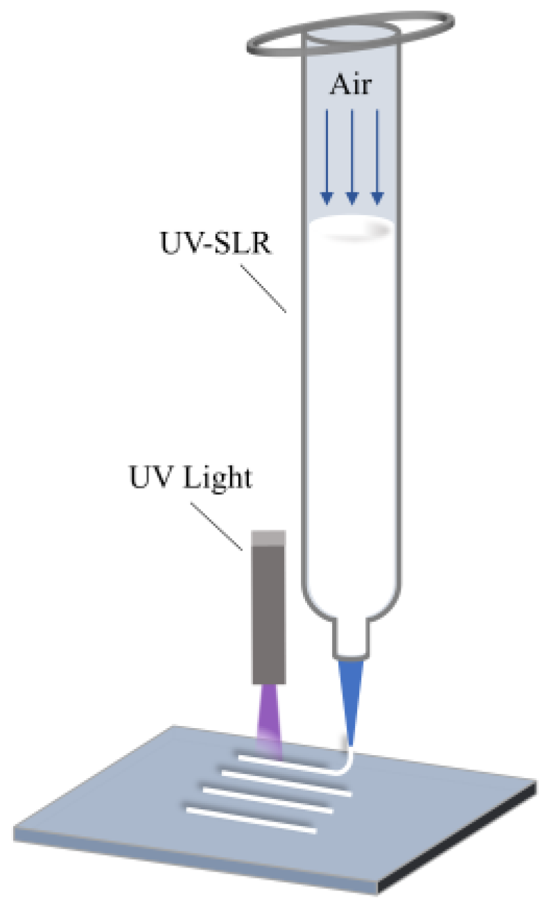
2.2. Process of UFC
2.3. Rheological Property
2.4. Sample Preparation
2.5. Statistical Analysis
2.6. Mechanical Properties
3. Results and Discussion
3.1. Silicone Ink
3.2. The Impact of UFC on the Precision of Filament Dimensions
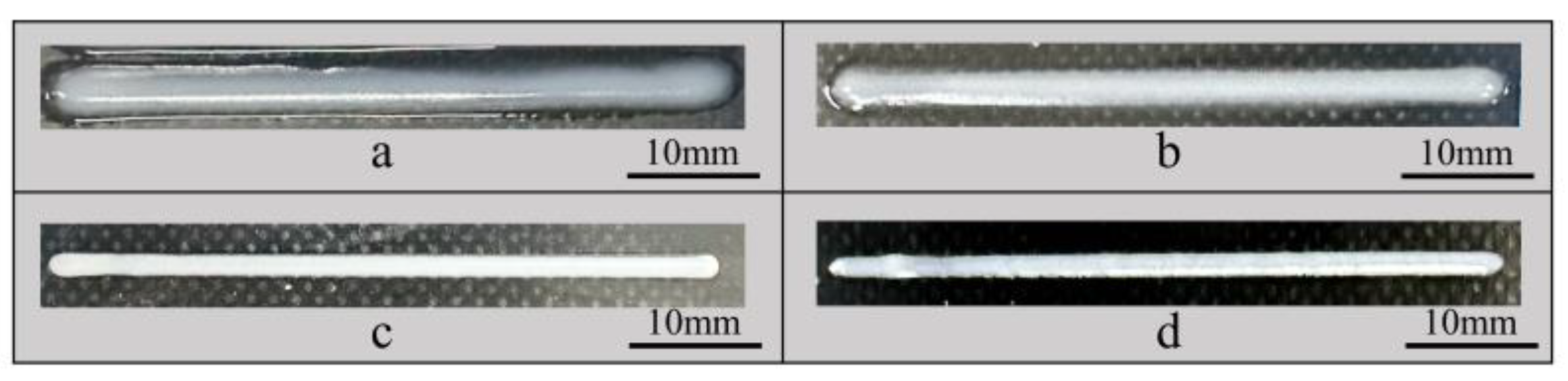
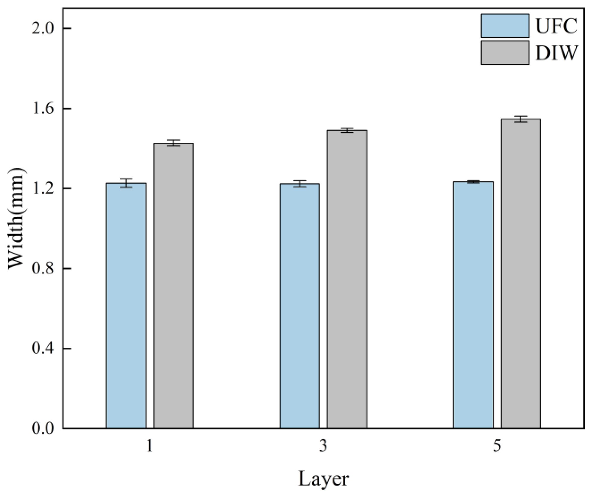
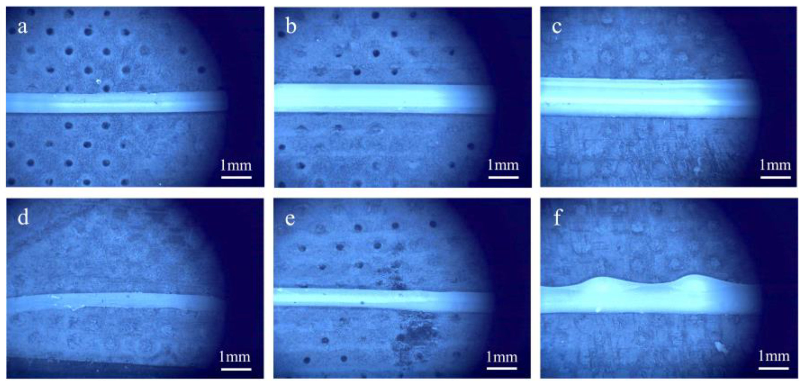
3.2.1. Single Filament
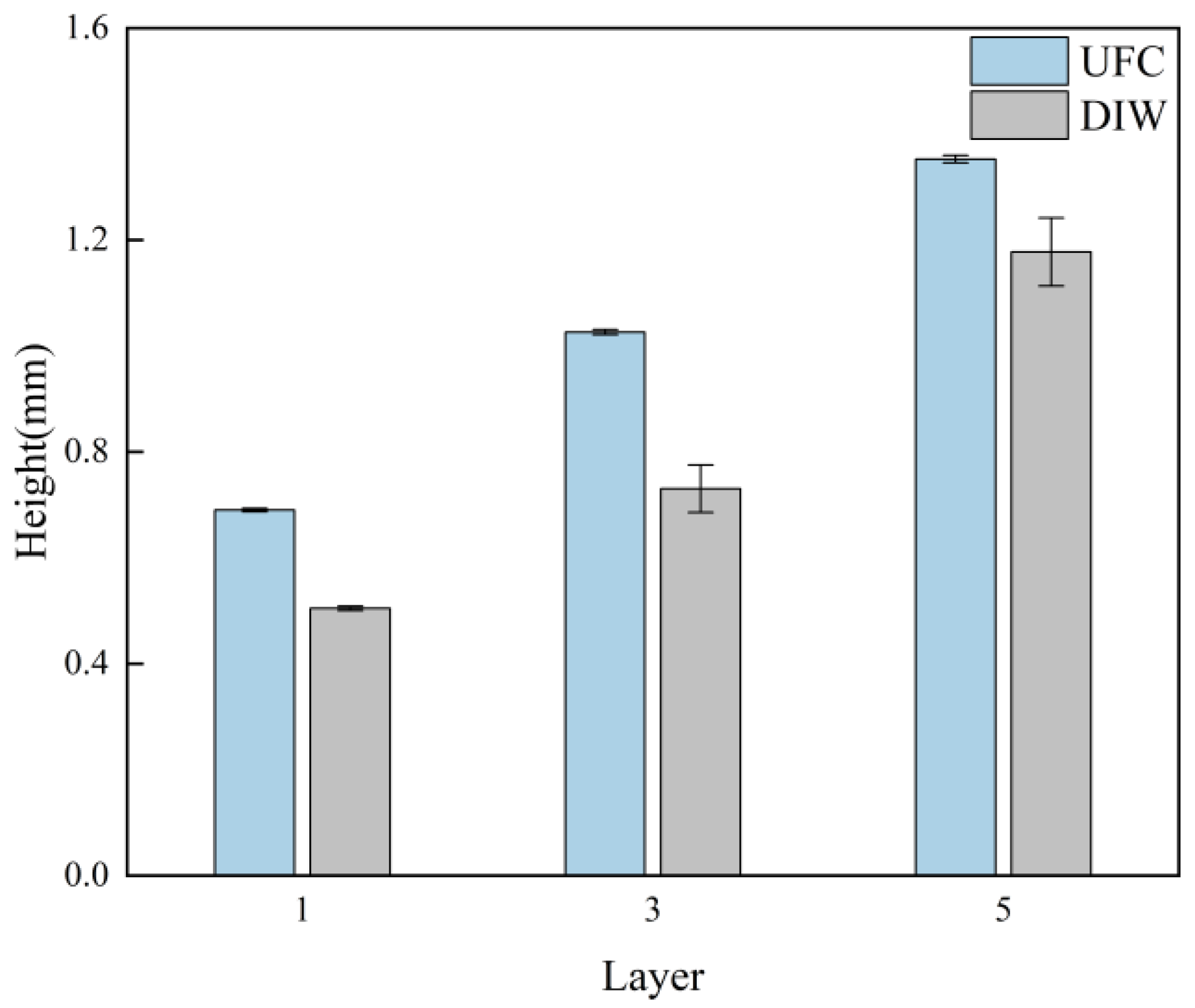
3.2.2. Single Wall
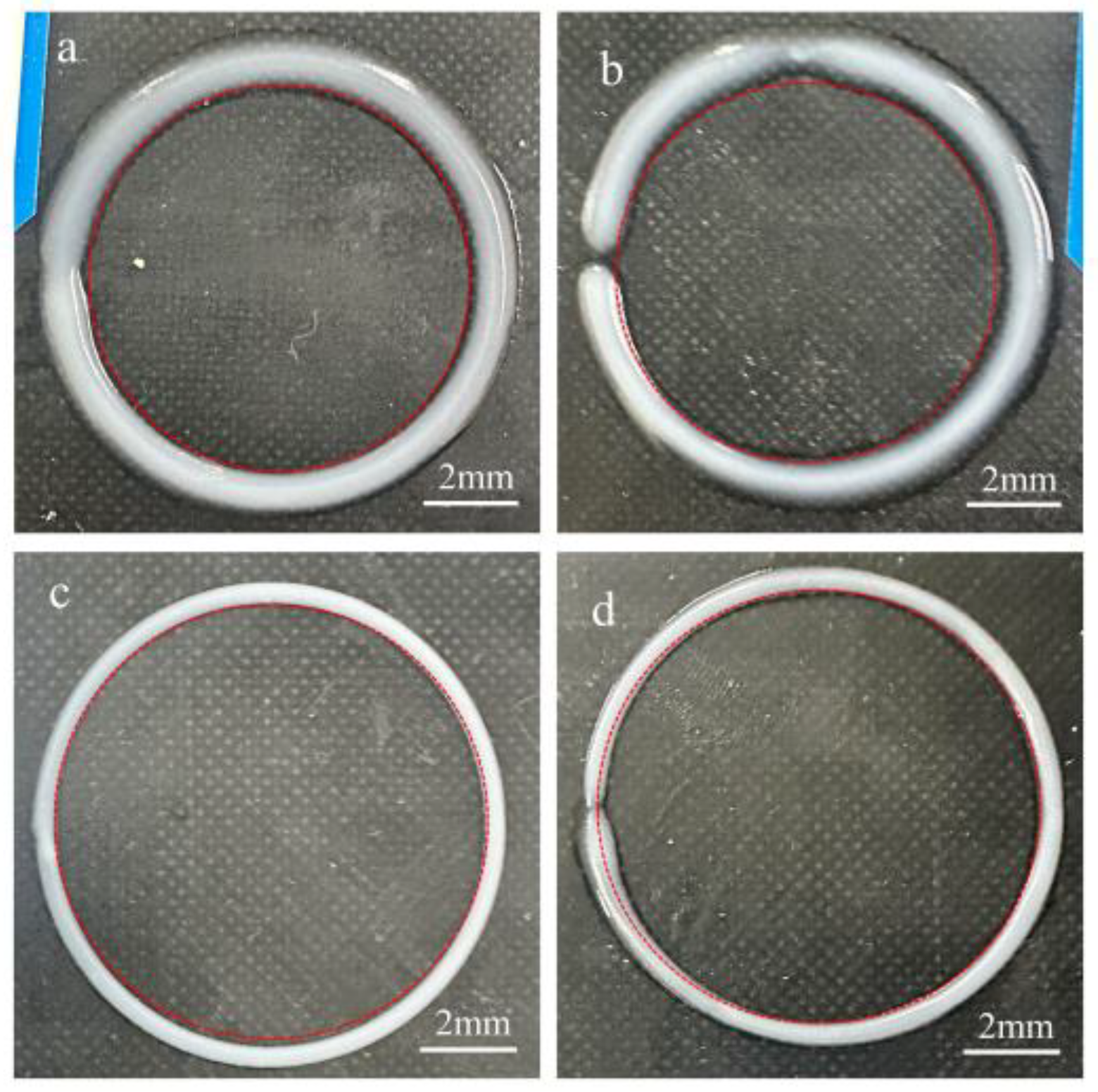
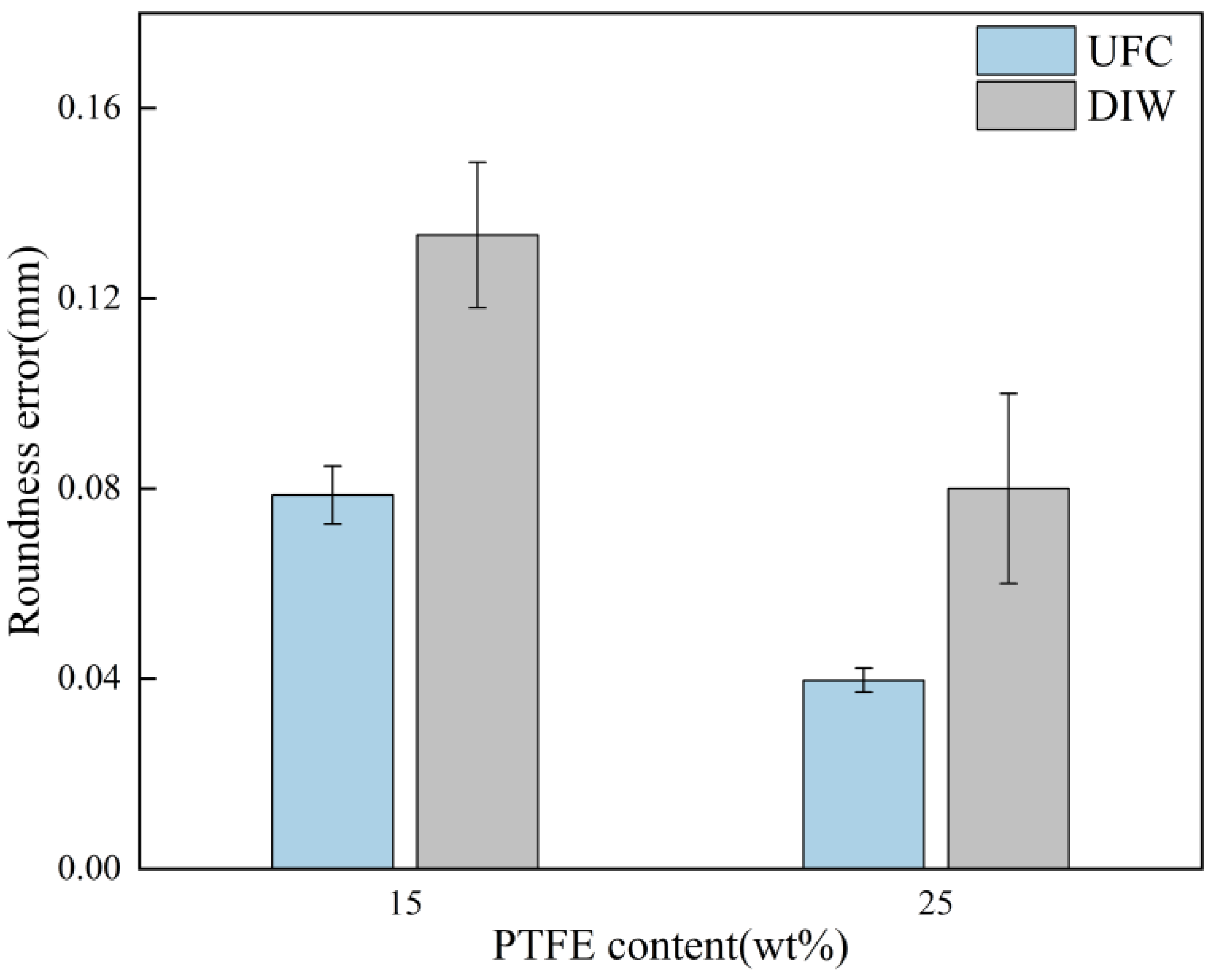
3.2.3. Circular Ring
3.2.4. Hollow Cylinder
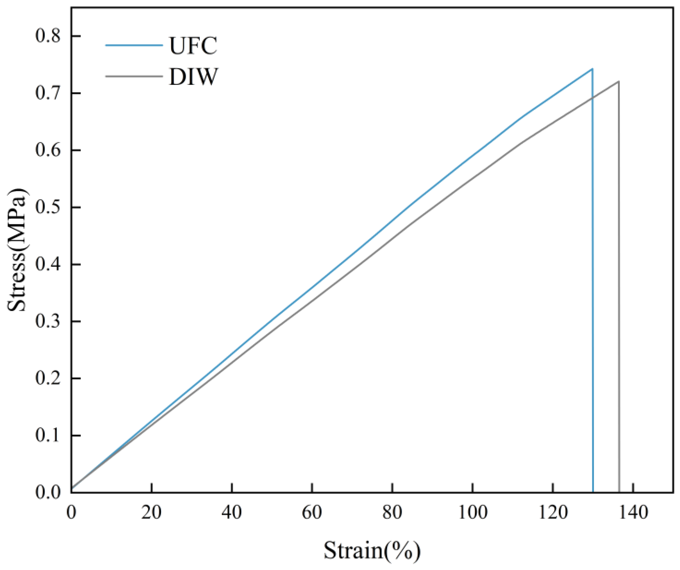
3.3. The Impact of UFC on Mechanical Properties
4. Conclusions
Supplementary Materials
Author Contributions
Funding
Institutional Review Board Statement
Data Availability Statement
Conflicts of Interest
References
- Liravi, F.; Darleux, R.; Toyserkani, E. Additive manufacturing of 3D structures with non-Newtonian highly viscous fluids: Finite element modeling and experimental validation. Addit. Manuf. 2017, 13, 113–123. [Google Scholar] [CrossRef]
- Liravi, F.; Toyserkani, E. Additive manufacturing of silicone structures: A review and prospective. Addit. Manuf. 2018, 24, 232–242. [Google Scholar] [CrossRef]
- Li, J.; Wu, S.; Zhang, W.; Ma, K.; Jin, G. 3D printing of silicone elastomers for soft actuators. Actuators 2022, 11, 200. [Google Scholar] [CrossRef]
- Gutierrez, D.B.; Caldona, E.B.; Yang, Z.; Suo, X.; Cheng, X.; Dai, S.; Espiritu, R.D.; Advincula, R.C. PDMS-silica composite gas separation membranes by direct ink writing. J. Appl. Polym. Sci. 2023, 140, e54277. [Google Scholar] [CrossRef]
- Shrestha, M.; Depari, L.; Shakerzadeh, M.; Shivakumar, R.; Teo, E.H. Ink-based transparent compliant electrode for direct coating on untreated hydrophobic PDMS surfac. Sens. Actuators Rep. 2023, 5, 100162. [Google Scholar] [CrossRef]
- Robinson, S.S.; O’Brien, K.W.; Zhao, H.; Peele, B.N.; Larson, C.M.; Mac Murray, B.C.; Van Meerbeek, I.M.; Dunham, S.N.; Shepherd, R.F. Integrated soft sensors and elastomeric actuators for tactile machines with kinesthetic sense. Extrem. Mech. Lett. 2015, 5, 47. [Google Scholar] [CrossRef]
- Zhu, G.; Dai, H.; Yao, Y.; Tang, W.; Shi, J.; Yang, J.; Zhu, L. 3D printed skin-inspired flexible pressure sensor with gradient porous structure for tunable high sensitivity and wide linearity range. Adv. Mater. Technol. 2022, 7, 2101239. [Google Scholar] [CrossRef]
- Xiao, Y.; Guo, D.; Yang, L.; Tong, Y.; Wu, X.; Wang, Y. Fabric-based capacitive pressure sensors for porous four-phase composites with high sensitivity and wide linearity range. Compos. Sci. Technol. 2024, 256, 110794. [Google Scholar] [CrossRef]
- Tian, K.; Bae, J.; Bakarich, S.E.; Yang, C.; Gately, R.D.; Spinks, G.M.; Marc in het Panhuis; Suo, Z.; Vlassak, J.J. 3D printing of transparent and conductive heterogeneous hydrogel–elastomer systems. Adv. Mater. 2017, 29, 1604827. [Google Scholar] [CrossRef]
- Goh, G.L.; Agarwala, S.; Yeong, W.Y. Directed and on-demand alignment of carbon nanotube: A review toward 3D printing of electronics. Adv. Mater. Interfaces 2019, 6, 1801318. [Google Scholar] [CrossRef]
- Tian, X.; Plott, J.; Wang, H.; Zhu, B.; Shih, A.J. Silicone foam additive manufacturing by liquid rope coiling. Procedia CIRP 2017, 65, 196–201. [Google Scholar] [CrossRef]
- Tugui, C.; Cazacu, M.; Manoli, D.M.; Stefan, A.; Duduta, M. All-silicone 3D printing technology: Toward highly elastic dielectric elastomers and complex structures. ACS Appl. Polym. Mater. 2023, 5, 7936–7946. [Google Scholar] [CrossRef]
- Cheng, Y.; Chan, K.H.; Wang, X.Q.; Ding, T.; Li, T.; Lu, X.; Ho, G.W. Direct-ink-write 3D printing of hydrogels into biomimetic soft robots. ACS Nano 2019, 13, 13176–13184. [Google Scholar] [CrossRef] [PubMed]
- Yeo, J.; Koh, J.J.; Wang, F.; Li, Z.; He, C. 3D printing silicone materials and devices. Silicon Contain. Hybrid Copolym. 2020, 9, 239–263. [Google Scholar]
- Plott, J.; Tian, X.; Shih, A.J. Voids and tensile properties in extrusion-based additive manufacturing of moisture-cured silicone elastomer. Addit. Manuf. 2018, 22, 606–617. [Google Scholar] [CrossRef]
- Plott, J.; Shih, A. The extrusion-based additive manufacturing of moisture-cured silicone elastomer with minimal void for pneumatic actuators. Addit. Manuf. 2017, 17, 1–14. [Google Scholar] [CrossRef]
- Geng, C.; Ding, Z.; Qian, W.; Su, Y.; Yu, F.; Zhang, Y.; Chen, Y.; Liu, Y.; Lu, A. 3D Printed Architectured silicone composites containing a UV-curable rheological modifier with tailorable structural collapse. Compos. Part B Eng. 2024, 280, 111490. [Google Scholar] [CrossRef]
- Zheng, R.; Chen, Y.; Chi, H.; Qiu, H.; Xue, H.; Bai, H. 3D printing of a polydimethylsiloxane/polytetrafluoroethylene composite elastomer and its application in a triboelectric nanogenerator. ACS Appl. Mater. Interfaces 2020, 12, 57441–57449. [Google Scholar] [CrossRef]
- Xu, P.; Zhu, L.; Chang, B. Liquid Metal/Sodium Alginate Composites for Direct-Ink-Writing Functional Soft Components of a Variable-Stiffness Soft Robot. ACS Appl. Electron. Mater. 2024, 6, 8838–8848. [Google Scholar] [CrossRef]
- García-Tuñón, E.; Feilden, E.; Zheng, H.; D’Elia, E.; Leong, A.; Saiz, E. Graphene oxide: An all-in-one processing additive for 3D printing. ACS Appl. Mater. Interfaces 2017, 9, 32977–32989. [Google Scholar] [CrossRef]
- Jiang, Z.; Erol, O.; Chatterjee, D.; Xu, W.; Hibino, N.; Romer, L.H.; Kang, S.H.; Gracias, D.H. Direct ink writing of poly (tetrafluoroethylene) (PTFE) with tunable mechanical properties. ACS Appl. Mater. Interfaces 2019, 11, 28289–28295. [Google Scholar] [CrossRef]
- Muth, J.T.; Dixon, P.G.; Woish, L.; Gibson, L.J.; Lewis, J.A. Architected cellular ceramics with tailored stiffness via direct foam writing. Proc. Natl. Acad. Sci. USA 2017, 114, 1832–1837. [Google Scholar] [CrossRef] [PubMed]
- Roh, S.; Parekh, D.P.; Bharti, B.; Stoyanov, S.D.; Velev, O.D. 3D printing by multiphase silicone/water capillary inks. Adv. Mater. 2017, 29, 1701554. [Google Scholar] [CrossRef]
- Ji, Z.; Jiang, D.; Zhang, X.; Guo, Y.; Wang, X. Facile Photo and Thermal Two-Stage Curing for High-Performance 3D Printing of Poly (Dimethylsiloxane). Macromol. Rapid Commun. 2020, 41, 2000064. [Google Scholar] [CrossRef] [PubMed]
- Zhu, C.; Han, T.Y.J.; Duoss, E.B.; Golobic, A.M.; Kuntz, J.D.; Spadaccini, C.M.; Worsley, M.A. Highly compressible 3D periodic graphene aerogel microlattices. Nat. Commun. 2015, 6, 6962. [Google Scholar] [CrossRef] [PubMed]
- Nadgorny, M.; Xiao, Z.; Connal, L.A. 2D and 3D-printing of self-healing gels: Design and extrusion of self-rolling objects. Mol. Syst. Des. Eng. 2017, 2, 283–292. [Google Scholar] [CrossRef]
- Xiang, H.; Yin, J.; Lin, G.; Liu, X.; Rong, M.; Zhang, M. Photo-crosslinkable, self-healable and reprocessable rubbers. Chem. Eng. J. 2019, 358, 878–890. [Google Scholar] [CrossRef]
- Chen, K.; Kuang, X.; Li, V.; Kang, G.; Qi, H.J. Fabrication of tough epoxy with shape memory effects by UV-assisted direct-ink write printing. Soft Matter 2018, 14, 1879–1886. [Google Scholar] [CrossRef]
- Chen, H.; Wang, X.; Xue, F.; Huang, Y.; Zhou, K.; Zhang, D. 3D printing of SiC ceramic: Direct ink writing with a solution of preceramic polymers. J. Eur. Ceram. Soc. 2018, 38, 5294–5300. [Google Scholar] [CrossRef]
- Rau, D.A.; Herzberger, J.; Long, T.E.; Williams, C.B. Ultraviolet-assisted direct ink write to additively manufacture all-aromatic polyimides. ACS Appl. Mater. Interfaces 2018, 10, 34828–34833. [Google Scholar] [CrossRef]
- Rios, O.; Carter, W.; Post, B.; Lloyd, P.; Fenn, D.; Kutchko, C.; Rock, R.; Olson, K.; Compton, B. 3D printing via ambient reactive extrusion. Mater. Today Commun. 2018, 15, 333–336. [Google Scholar] [CrossRef]
- Boley, J.W.; Chaudhary, K.; Ober, T.J.; Khorasaninejad, M.; Chen, W.T.; Hanson, E.; Kulkarni, A.; Oh, J.; Kim, J.; Aagesen, L.K.; et al. High-operating-temperature direct ink writing of mesoscale eutectic architectures. Adv. Mater. 2017, 29, 7. [Google Scholar] [CrossRef] [PubMed]
- Deuser, B.K.; Tang, L.; Landers, R.G.; Leu, M.C.; Hilmas, G.E. Hybrid extrusion force-velocity control using freeze-form extrusion fabrication for functionally graded material parts. J. Manuf. Sci. Eng. 2013, 135, 041015. [Google Scholar] [CrossRef]
- Nelson, A.Z.; Bras, R.E.; Liu, J.; Ewoldt, R.H. Extending yield-stress fluid paradigms. J. Rheol. 2018, 62, 357–369. [Google Scholar] [CrossRef]
- Romberg, S.K.; Islam, M.A.; Hershey, C.J.; DeVinney, M.; Duty, C.E.; Kunc, V.; Compton, B.G. Linking thermoset ink rheology to the stability of 3D-printed structures. Addit. Manuf. 2021, 37, 101621. [Google Scholar] [CrossRef]
- Bruneaux, J.; Therriault, D.; Heuzey, M.C. Micro-extrusion of organic inks for direct-write assembly. J. Micromech. Microeng. 2008, 18, 115020. [Google Scholar] [CrossRef]
- Ma, Z.; Zhang, X.; Liu, H.; Lu, S.; Qin, L.; Dong, G. Direct ink writing of reinforced polydimethylsiloxane elastomer composites for flexure sensors. J. Appl. Polym. Sci. 2022, 139, e53153. [Google Scholar] [CrossRef]
- Chen, X.; Li, J.; Cao, Y.; Lan, Y.; Qiao, Z. Straight and smooth GaN nanowires. Adv. Mater. 2000, 12, 1432–1434. [Google Scholar] [CrossRef]
- Liu, B.; Ma, B. 3D printing molding of UV-curing liquid silicone rubber by UV follow curing. J. Appl. Polym. Sci. 2025, 142, e56453. [Google Scholar] [CrossRef]
- ASTM D638-03; Standard Test Method for Tensile Properties of Plastics. ASTM: West Conshohocken, PA, USA, 2012.


| Method | Material Type | Curing Time | Width-Dimensional Error [%] | Length-Dimensional Error [%] | Mechanical Strength [MPa] |
|---|---|---|---|---|---|
| UFC | 15 wt% PTFE | 2 s | 46.7 | 0.27 | |
| 25 wt% PTFE | 2 s | 212.6 | 2.2 | 0.74 | |
| DIW | 15 wt% PTFE | Depends on the printing time | 68.5 | 2.07 | |
| 25 wt% PTFE | Depends on the printing time | 294.3 | 3.6 | 0.72 |
Disclaimer/Publisher’s Note: The statements, opinions and data contained in all publications are solely those of the individual author(s) and contributor(s) and not of MDPI and/or the editor(s). MDPI and/or the editor(s) disclaim responsibility for any injury to people or property resulting from any ideas, methods, instructions or products referred to in the content. |
© 2025 by the authors. Licensee MDPI, Basel, Switzerland. This article is an open access article distributed under the terms and conditions of the Creative Commons Attribution (CC BY) license (https://creativecommons.org/licenses/by/4.0/).
Share and Cite
Liu, B.; Ma, B. Ultraviolet-Follow Curing-Mediated Extrusion Stabilization for Low-Yield-Stress Silicone Rubbers: From Die Swell Suppression to Dimensional Accuracy Enhancement. Polymers 2025, 17, 811. https://doi.org/10.3390/polym17060811
Liu B, Ma B. Ultraviolet-Follow Curing-Mediated Extrusion Stabilization for Low-Yield-Stress Silicone Rubbers: From Die Swell Suppression to Dimensional Accuracy Enhancement. Polymers. 2025; 17(6):811. https://doi.org/10.3390/polym17060811
Chicago/Turabian StyleLiu, Bing, and Baoji Ma. 2025. "Ultraviolet-Follow Curing-Mediated Extrusion Stabilization for Low-Yield-Stress Silicone Rubbers: From Die Swell Suppression to Dimensional Accuracy Enhancement" Polymers 17, no. 6: 811. https://doi.org/10.3390/polym17060811
APA StyleLiu, B., & Ma, B. (2025). Ultraviolet-Follow Curing-Mediated Extrusion Stabilization for Low-Yield-Stress Silicone Rubbers: From Die Swell Suppression to Dimensional Accuracy Enhancement. Polymers, 17(6), 811. https://doi.org/10.3390/polym17060811