
Phase-Change Materials as Cryo-Shock Absorbers in Rigid Polyurethane Cryogenic Insulation Foams

 , and
, and 
Abstract
1. Introduction
2. Materials and Methods
2.1. Materials
2.2. Preparation of Rigid PU Foams
2.3. Apparent Density
2.4. Apparent Viscosity
2.5. Coefficient of Thermal Conductivity
2.6. Compression Strength
2.7. Tensile Strength
2.8. Adhesion
2.9. Differential Scanning Calorimetry
2.10. Dynamic Mechanical Analysis
2.11. Thermomechanical Analysis and Safety Coefficient
2.12. Scanning Electron Microscopy (SEM)
3. Results and Discussion
3.1. Characterization of PCM
3.2. Density and Thermal Conductivity of PU Foams with Microencapsulated PCM
3.3. Properties of Poured Rigid PU Foams
3.4. Properties of Sprayed Rigid PU Foams
4. Conclusions
5. Patents
Supplementary Materials
Author Contributions
Funding
Institutional Review Board Statement
Data Availability Statement
Acknowledgments
Conflicts of Interest
References
- Ratnakar, R.R.; Sun, Z.; Balakotaiah, V. Effective thermal conductivity of insulation materials for cryogenic LH2 storage tanks: A review. Int. J. Hydrogen Energy 2023, 48, 7770–7793. [Google Scholar] [CrossRef]
- International Institute of Refrigeration International Dictionary of Refrigeration. Available online: https://dictionary.iifiir.org/index.php?dispLang=en (accessed on 17 May 2024).
- Vevere, L.; Yakushin, V.; Sture-Skela, B.; Andersons, J.; Cabulis, U. Cryogenic Insulation—Towards Environmentally Friendly Polyurethane Foams. Polymers 2024, 16, 2406. [Google Scholar] [CrossRef] [PubMed]
- Long-Term Aspirational Goal Overview of Climate Goals and ICAO’s Work on a Long-Term Aspirational Goal for International Aviation (LTAG). Available online: https://www.icao.int/environmental-protection/Documents/EnvironmentalReports/2022/ENVReport2022_Art22.pdf (accessed on 17 May 2024).
- Ye, C.; Lin, Y.; Pei, F. Comparative study of three insulation materials installed on type C independent tank for offshore LNG transportation. Cryogenics 2022, 126, 103521. [Google Scholar] [CrossRef]
- Song, H.-C. Assessment of Cryogenic Material Properties of R-PUF Used in the CCS of an LNG Carrier. J. Ocean Eng. Technol. 2022, 36, 217–231. [Google Scholar] [CrossRef]
- Kim, J.D.; Kim, J.H.; Lee, D.H.; Yeom, D.J.; Lee, J.M. Synthesis and investigation of cryogenic mechanical properties of chopped-glass-fiber-reinforced polyisocyanurate foam. Materials 2021, 14, 446. [Google Scholar] [CrossRef]
- Park, J.H.; Oh, D.J.; Kim, M.H.; Kim, K.H.; Kim, M.K.; Moon, H.S. Fatigue Strength of a LNGC Secondary Barrier Made of a Composite Material with Aramid Fibers. Mech. Compos. Mater. 2018, 54, 431–442. [Google Scholar] [CrossRef]
- Tran, V.H.; Kim, J.D.; Kim, J.H.; Kim, S.K.; Lee, J.M. Infuence of Cellulose Nanocrystal on the Cryogenic Mechanical Behavior and Thermal Conductivity of Polyurethane Composite. J. Polym. Environ. 2020, 28, 1169–1179. [Google Scholar] [CrossRef]
- Yin, L.; Yang, H.; Ju, Y. Review on the key technologies and future development of insulation structure for liquid hydrogen storage tanks. Int. J. Hydrogen Energy 2024, 57, 1302–1315. [Google Scholar] [CrossRef]
- Timmerhaus, K.D. Cryogenic Process Engineering, 1st ed.; Springer: New York, NY, USA, 1989; pp. 13–36. [Google Scholar]
- Regulation (EU) No 517/2014 of the European Parliament and of the Council of 16 April 2014 on Fluorinated Greenhouse Gases and Repealing Regulation (EC) No 842/2006 Text with EEA Relevance. Available online: https://eur-lex.europa.eu/eli/reg/2014/517/oj/eng (accessed on 17 May 2024).
- Yakushin, V.; Rundans, M.; Holynska, M.; Sture, B.; Cabulis, U. Influence of Reactive Amine-Based Catalysts on Cryogenic Properties of Rigid Polyurethane Foams for Space and On-Ground Applications. Materials 2023, 16, 2798. [Google Scholar] [CrossRef]
- Yakushin, V.; Cabulis, U.; Fridrihsone, V.; Kravchenko, S.; Pauliks, R. Properties of polyurethane foam with fourth-generation blowing agent. e-Polymers 2021, 21, 763–769. [Google Scholar] [CrossRef]
- Uram, K.; Prociak, A.; Kurańska, M. Influence of the chemical structure of rapeseed oil-based polyols on selected properties of polyurethane foams. Polimery/Polymers 2020, 65, 698–707. [Google Scholar] [CrossRef]
- Mizera, K.; Ryszkowska, J.; Kurańska, M.; Prociak, A. The effect of rapeseed oil-based polyols on the thermal and mechanical properties of ureaurethane elastomers. Polym. Bull. 2020, 77, 823–846. [Google Scholar] [CrossRef]
- Liu, F.; Chen, S. The Preparation and Characterization of Polyurethane Foam with Coconut Oil Polyol and Rapeseed Oil Polyol. J. Polym. Environ. 2021, 29, 2421–2434. [Google Scholar] [CrossRef]
- Dingcong, R.G.; Malaluan, R.M.; Alguno, A.C.; Estrada, D.J.E.; Lubguban, A.A.; Resurreccion, E.P.; Dumancas, G.G.; Al-Moameri, H.H.; Lubguban, A.A. A novel reaction mechanism for the synthesis of coconut oil-derived biopolyol for rigid poly(urethane-urea) hybrid foam application. RSC Adv. 2023, 13, 1985–1994. [Google Scholar] [CrossRef]
- Leng, X.; Li, C.; Cai, X.; Yang, Z.; Zhang, F.; Liu, Y.; Yang, G.; Wang, Q.; Fang, G.; Zhang, X. A study on coconut fatty acid diethanolamide-based polyurethane foams. RSC Adv. 2022, 12, 13548–13556. [Google Scholar] [CrossRef]
- Omisol CJ, M.; Aguinid BJ, M.; Abilay, G.Y.; Asequia, D.M.; Tomon, T.R.; Sabulbero, K.X.; Erjeno, D.J.; Osorio, C.K.; Usop, S.; Malaluan, R.; et al. Flexible Polyurethane Foams Modified with Novel CoconutMonoglycerides-Based Polyester Polyols. ACS Omega 2024, 9, 4497–4512. [Google Scholar] [CrossRef]
- Yang, F.; Yu, H.; Deng, Y.; Xu, X. Synthesis and characterization of different soybean oil-based polyols with fatty alcohol and aromatic alcohol. e-Polymers 2021, 21, 491–499. [Google Scholar] [CrossRef]
- He, W.; Kang, P.; Fang, Z.; Hao, J.; Wu, H.; Zhu, Y.; Guo, K. Flow Reactor Synthesis of Bio-Based Polyol from Soybean Oil for the Production of Rigid Polyurethane Foam. Ind. Eng. Chem. Res. 2020, 59, 17513–17519. [Google Scholar] [CrossRef]
- Frias, C.F.; Fonseca, A.C.; Coelho, J.F.; Serra, A.C. Straightforward Synthesis of Amido Polyols from EpoxidizedSoybean Oil for Polyurethane Films. Macromol. Mater. Eng. 2021, 306, 2100453. [Google Scholar] [CrossRef]
- Ivdre, A.; Kirpluks, M.; Abolins, A.; Vevere, L.; Sture, B.; Paze, A.; Godina, D.; Rizikovs, J.; Cabulis, U. Rigid Polyurethane Foams’ Development and Optimization from Polyols Based on Depolymerized Suberin and Tall Oil Fatty Acids. Polymers 2024, 16, 942. [Google Scholar] [CrossRef]
- Serrano-Martínez, V.M.; Hernández-Fernández, C.; Pérez-Aguilar, H.; Carbonell-Blasco, M.P.; García-García, A.; Orgilés-Calpena, E. Development and Application of a Lignin-Based Polyol for Sustainable Reactive Polyurethane Adhesives Synthesis. Polymers 2024, 16, 1928. [Google Scholar] [CrossRef] [PubMed]
- Gotkiewicz, O.; Kirpluks, M.; Walterová, Z.; Kočková, O.; Abbrent, S.; Parcheta-Szwindowska, P.; Cabulis, U.; Beneš, H. Biobased Ultralow-Density Polyurethane Foams with Enhanced Recyclability. ACS Sustain. Chem. Eng. 2024, 12, 1605–1615. [Google Scholar] [CrossRef]
- Fridrihsone, A.; Romagnoli, F.; Kirsanovs, V.; Cabulis, U. Life Cycle Assessment of vegetable oil based polyols for polyurethane production. J. Clean. Prod. 2020, 266, 121403. [Google Scholar] [CrossRef]
- Staccioli, L.; Rodrigues dos Santos, A.M.; Gallego, J.; Kalliola, A.; Fearon, O.; Ortiz, P.; Pitacco, W.; Carvalho, A. A life cycle assessment model to evaluate the environmental sustainability of lignin-based polyols. Sustain. Prod. Consum. 2024, 52, 624–639. [Google Scholar] [CrossRef]
- Churchill, J.G.B.; Borugadda, V.B.; Dalai, A.K. A review on the production and application of tall oil with a focus on sustainable fuels. Renew. Sustain. Energy Rev. 2024, 191, 114098. [Google Scholar] [CrossRef]
- Sha, Y.; Hua, W.; Cao, H.; Zhang, X. Properties and encapsulation forms of phase change material and various types of cold storage box for cold chain logistics: A review. J. Energy Storage 2022, 55, 105426. [Google Scholar] [CrossRef]
- Calati, M.; Hooman, K.; Mancin, S. Thermal storage based on phase change materials (PCMs) for refrigerated transport and distribution applications along the cold chain: A review. Int. J. Thermofluids 2022, 16, 100224. [Google Scholar] [CrossRef]
- Tafone, A.; Borri, E.; Cabeza, L.F.; Romagnoli, A. Innovative cryogenic Phase Change Material (PCM) based cold thermal energy storage for Liquid Air Energy Storage (LAES)—Numerical dynamic modelling and experimental study of a packed bed unit. Appl. Energy 2021, 301, 117417. [Google Scholar] [CrossRef]
- Goitandia, A.M.; Beobide, G.; Vadillo, J.; del Val, I.; Aranzabe, E.; Aranzabe, A. Invigorating polyurethane foams with phase change materials supported in inorganic containers. Polym. Compos. 2018, 39, 1420–1432. [Google Scholar] [CrossRef]
- Pomianowski, M.; Heiselberg, P.; Zhang, Y. Review of thermal energy storage technologies based on PCM application in buildings. Energy Build. 2013, 67, 56–69. [Google Scholar] [CrossRef]
- Yang, C.; Fischer, L.; Maranda, S.; Worlitschek, J. Rigid polyurethane foams incorporated with phase change materials: A state-of-the-art review and future research pathways. Energy Build. 2015, 87, 25–36. [Google Scholar] [CrossRef]
- Shchukina, E.M.; Graham, M.; Zheng, Z.; Shchukin, D.G. Nanoencapsulation of phase change materials for advanced thermal energy storage systems. Chem. Soc. Rev. 2018, 47, 4156–4175. [Google Scholar] [CrossRef] [PubMed]
- Jacob, R.; Bruno, F. Review on shell materials used in the encapsulation of phase change materials for high temperature thermal energy storage. Renew. Sustain. Energy Rev. 2015, 48, 79–87. [Google Scholar] [CrossRef]
- Amaral, C.; Pinto, S.C.; Silva, T.; Mohseni, F.; Amaral, J.S.; Amaral, V.S.; Marques, P.A.A.P.; Barros-Timmons, A.; Vicente, R. Development of polyurethane foam incorporating phase change material for thermal energy storage. J. Energy Storage 2020, 28, 101177. [Google Scholar] [CrossRef]
- Galvagnini, F.; Valentini, F.; Dorigato, A. Development of polymeric insulating foams for low-temperature thermal energy storage applications. J. Appl. Polym. Sci. 2022, 139, e52397. [Google Scholar] [CrossRef]
- Ryms, M.; Januszewicz, K.; Haustein, E.; Kazimierski, P.; Lewandowski, W.M. Thermal properties of a cement composite containing phase change materials (PCMs) with post-pyrolytic char obtained from spent tyres as a carrier. Energy 2022, 239, 121936. [Google Scholar] [CrossRef]
- Borreguero, A.M.; Rodríguez, J.F.; Valverde, J.L.; Peijs, T.; Carmona, M. Characterization of rigid polyurethane foams containing microencapsulted phase change materials: Microcapsules type effect. J. Appl. Polym. Sci. 2013, 128, 582–590. [Google Scholar] [CrossRef]
- Khudhair, A.; Farid, M.; Ozkan, N.; Chen, J. Thermal Performance and Mechanical Testing of Gypsum Wallboard with Latent Heat Storage. In Proceedings of the Experts Meeting and Conference on Thermal Energy Technologies, Indore, India, 21–24 March 2003. [Google Scholar]
- Borreguero, A.M.; Carmona, M.; Sanchez, M.L.; Valverde, J.L.; Rodriguez, J.F. Improvement of the thermal behaviour of gypsum blocks by the incorporation of microcapsules containing PCMS obtained by suspension polymerization with an optimal core/coating mass ratio. Appl. Therm. Eng. 2010, 30, 1164–1169. [Google Scholar] [CrossRef]
- Cabeza, L.F.; Castellón, C.; Nogués, M.; Medrano, M.; Leppers, R.; Zubillaga, O. Use of microencapsulated PCM in concrete walls for energy savings. Energy Build. 2007, 39, 113–119. [Google Scholar] [CrossRef]
- Jin, R.; Xu, B.; Qu, L. Cryogenics performance enhancement of epoxy resin composites through negative expansion nanomaterials: Mechanism and predictive modeling. Polym. Compos. 2024, 45, 11892–11907. [Google Scholar] [CrossRef]
- Wang, X.; Ma, B.; Wei, K.; Si, W.; Kang, X.; Fang, Y.; Zhang, H.; Shi, J.; Zhou, X. Thermal storage properties of polyurethane solid-solid phase-change material with low phase-change temperature and its effects on performance of asphalt binders. J. Energy Storage 2022, 55, 105686. [Google Scholar] [CrossRef]
- Liang, S.; Zhu, Y.; Wang, H.; Wu, T.; Tian, C.; Wang, J.; Bai, R. Preparation and Characterization of Thermoregulated Rigid Polyurethane Foams Containing Nanoencapsulated Phase Change Materials. Ind. Eng. Chem. Res. 2016, 55, 2721–2730. [Google Scholar] [CrossRef]
- Xiang, H.; An, J.; Zeng, X.; Liu, X.; Li, Y.; Yang, C.; Xia, X. Preparation and properties of polyurethane rigid foam materials modified by microencapsulated phase change materials. Polym. Compos. 2020, 41, 1662–1672. [Google Scholar] [CrossRef]
- Zhai, X.; Wang, J.; Zhang, X.; Peng, H. Polyurethane foam based composite phase change microcapsules with reinforced thermal conductivity for cold energy storage. Colloids Surf. A Physicochem. Eng. Asp. 2022, 652, 129875. [Google Scholar] [CrossRef]
- Mahajan, U.R.; Emmanuel, I.; Rao, A.S.; Mhaske, S.T. Development of rigid polyurethane foam incorporating phase change material for a low-temperature thermal energy storage application. Polym. Int. 2023, 72, 490–499. [Google Scholar] [CrossRef]
- Trivedi, G.V.N.; Parameshwaran, R. Cryogenic conditioning of microencapsulated phase change material for thermal energy storage. Sci. Rep. 2020, 10, 18353. [Google Scholar] [CrossRef]
- Cabulis, U.; Yakushin, V.; Fischer, W.P.P.; Rundans, M.; Sevastyanova, I.; Deme, L. Rigid Polyurethane Foams as External Tank Cryogenic Insulation for Space Launchers. IOP Conf. Ser. Mater. Sci. Eng. 2019, 500, 012009. [Google Scholar] [CrossRef]
- Anthony, F.M.; Colt, J.Z.; Helenbrook, R.G. NASA Contractor Report 3404 Development and Validation of Cryogenic Foam Insulation for LH;I Subsonic Transports; NASA: Washington, DC, USA, 1981; p. 1096. [Google Scholar]
- ISO 845:2006; Cellular Plastics and Rubbers—Determination of Apparent Density. ISO: Geneva, Switzerland, 2006.
- ISO 8301:1991; Thermal Insulation—Determination of Steady-State Thermal Resistance and Related Properties—Heat Flow Meter Apparatus. ISO: Geneva, Switzerland, 1991.
- ISO 844:2021; Rigid Cellular Plastics—Determination of Compression Properties. ISO: Geneva, Switzerland, 2021.
- ISO 1926:2009; Rigid Cellular Plastics—Determination of Tensile Properties. ISO: Geneva, Switzerland, 2009.
- ASTM D2290-19a; Standard Test Method for Apparent Hoop Tensile Strength of Plastic or Reinforced Plastic Pipe. ASTM: West Conshohocken, PA, USA, 2019.
- EN 1607:2013; Thermal Insulating Products for Building Applications—Determination of Tensile Strength Perpendicular to Faces. CEN: Brussels, Belgium, 2013.
- Tanbar, F.; Nugroho, A.D.; Nugraha, A.D.; Darmanto, S.; Widagdo, D.; Santos, G.N.C.; Muflikhun, M.A. Hybrid lattice structure with micro graphite filler manufactured via additive manufacturing and growth foam polyurethane. Compos. Part C Open Access 2024, 15, 100516. [Google Scholar] [CrossRef]
- Gencel, O.; Aydoğmuş, E.; Güler, O.; Ustaoğlu, A.; Sarı, A.; Hekimoğlu, G.; Bozkurt, A.; Ozbakkaloglu, T. Sustainable polyurethane biocomposite foams by improved microstructure, acoustic characteristics, thermoregulation performance and reduced CO2 emission through phase change material integration. J. Energy Storage 2024, 103, 114372. [Google Scholar] [CrossRef]
- Bartczak, P.; Ejm, W.; Bacik, O.; Przybylska-Balcerek, A.; Borysiak, S. Camelina sativa (L.) Crantz straw and pomace as a green filler for integral skin polyurethane foam. Ind. Crops Prod. 2024, 222, 119931. [Google Scholar] [CrossRef]
- Michel, B.; Glouannec, P.; Fuentes, A.; Chauvelon, P. Experimental and numerical study of insulation walls containing a composite layer of PU-PCM and dedicated to refrigerated vehicle. Appl. Therm. Eng. 2017, 116, 382–391. [Google Scholar] [CrossRef]
- Qu, L.; Li, A.; Gu, J.; Zhang, C. Thermal Energy Storage Capability of Polyurethane Foams Incorporated with Microencapsulated Phase Change Material. ChemistrySelect 2018, 3, 3180–3186. [Google Scholar] [CrossRef]
- Liao, H.; Liu, Y.; Chen, R.; Wang, Q. Preparation and characterization of polyurethane foams containing microencapsulated phase change materials for thermal energy storage and thermal regulation. Polym. Int. 2021, 70, 619–627. [Google Scholar] [CrossRef]
- Gao, N.; Du, J.; Yang, W.; Li, Y.; Chen, N. Biomass-Based Shape-Stabilized Composite Phase-Change Materials with High Solar–Thermal Conversion Efficiency for Thermal Energy Storage. Polymers 2023, 15, 3747. [Google Scholar] [CrossRef]


| Weight, pbw | ||
|---|---|---|
| Poured | Sprayed | |
| ETO_DEOA | 15 | 15 |
| ETO_DEG | 10 | 10 |
| NEO240 | 50 | 50 |
| DEG | 25 | 25 |
| TCPP | 15 | 15 |
| Opteon 1100 | 31 | 31 |
| Water | 1.33 | 1.33 |
| Polycat 203 | 0.2 | 4 |
| Polycat 218 | 0.1 | 2 |
| Dabco MB 20 | 0.05 | 0.2 |
| Tegostab 84715 | 1.5 | 1.5 |
| PCM | 0–32.2 | 0−15.2 |
| pMDI | 148.8 | 148.8 |
| Parameter | Value |
|---|---|
| Melting temperature, °C | 29.3 ± 1.3 |
| Freezing temperature, °C | 24.5 ± 1.1 |
| Heat of fusion (melting), J/g | 178 ± 5 |
| Heat of freezing (crystallization), J/g | −176 ± 8 |
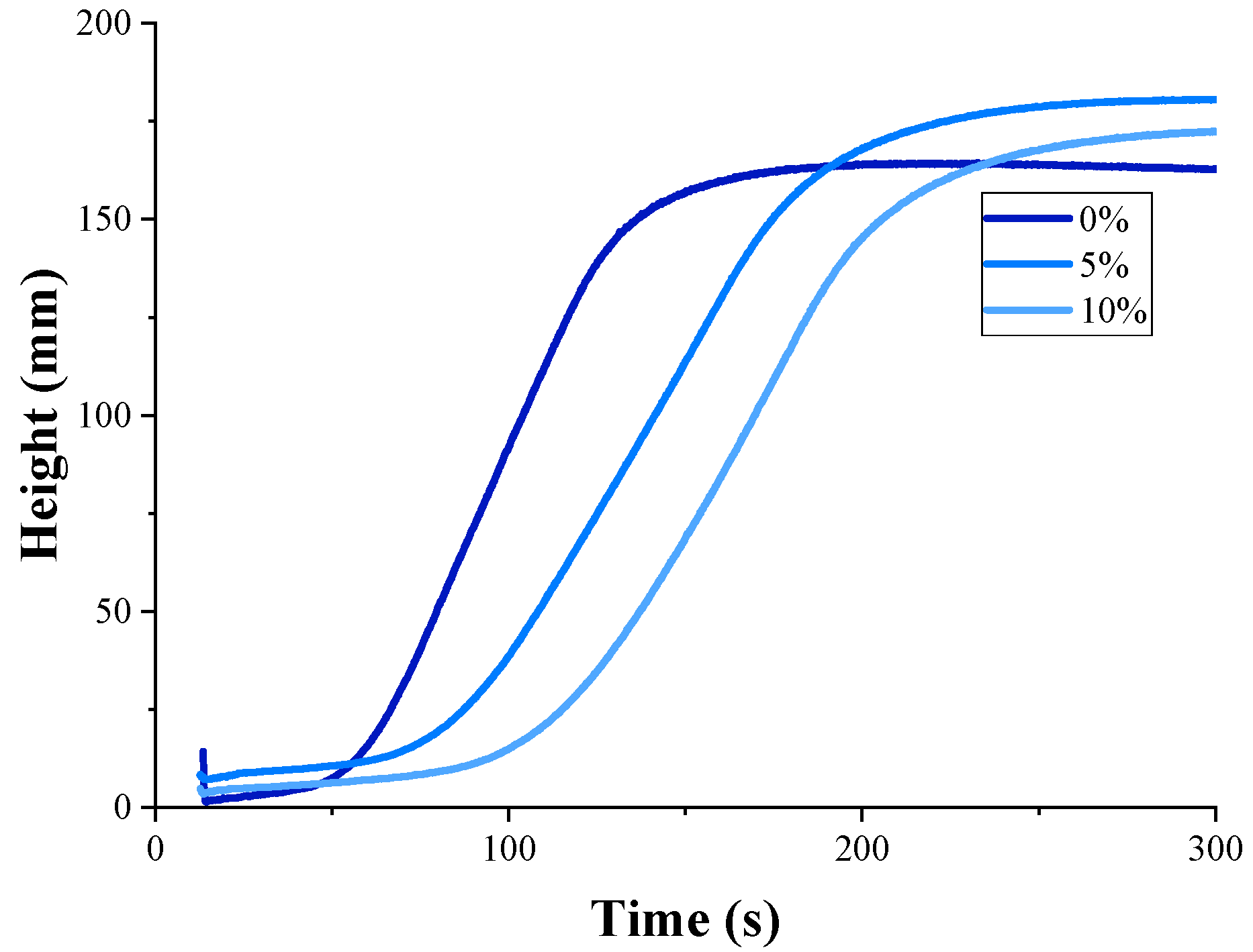
| PCM in Rigid PU Foams, % | Start Time, s | Rise Time, s | Maximal Temperature, °C | Apparent Viscosity, mPa·s |
|---|---|---|---|---|
| 0 | 49.7 ± 2.6 | 170.7 ± 3.7 | 53.6 ± 0.8 | 650 ± 40 |
| 2.5 | 62.0 ± 2.0 | 242.0 ± 3.0 | 52.2 ± 1.6 | 1600 ± 140 |
| 5 | 65.3 ± 0.0 | 232.6 ± 4.3 | 50.4 ± 1.2 | 3000 ± 340 |
| 7.5 | 79.7 ± 3.1 | 253.6 ± 4.5 | 50.0 ± 2.3 | 5200 ± 850 |
| 10 | 79.2 ± 1.7 | 270.0 ± 4.7 | 48.5 ± 1.1 | 6200 ± 1000 |
| PCM Content, % | Density, kg/m3 | Coefficient of Thermal Conductivity, mW/m·K | Closed Cell, % | |||
|---|---|---|---|---|---|---|
| Poured | Sprayed | Poured | Sprayed | Poured | Sprayed | |
| 0 | 36.7 ± 0.7 | 34.2 ± 0.7 | 19.49 ± 0.10 | 18.64 ± 0.11 | 98.4 ± 0.3 | 95.7 ± 0.5 |
| 2.5 | 38.4 ± 0.5 | 34.8 ± 0.2 | 19.98 ± 0.12 | 18.97 ± 0.11 | 94.2 ± 0.3 | 95.6 ± 0.6 |
| 5 | 39.6 ± 0.5 | 36.2 ± 0.9 | 19.58 ± 0.11 | 18.78 ± 0.23 | 93.2 ± 0.1 | 95.3 ± 0.5 |
| 7.5 | 40.0 ± 1.5 | 19.81 ± 0.15 | 91.9 ± 1.3 | |||
| 10 | 40.1 ± 0.9 | 19.63 ± 0.10 | 92.2 ± 0.5 | |||
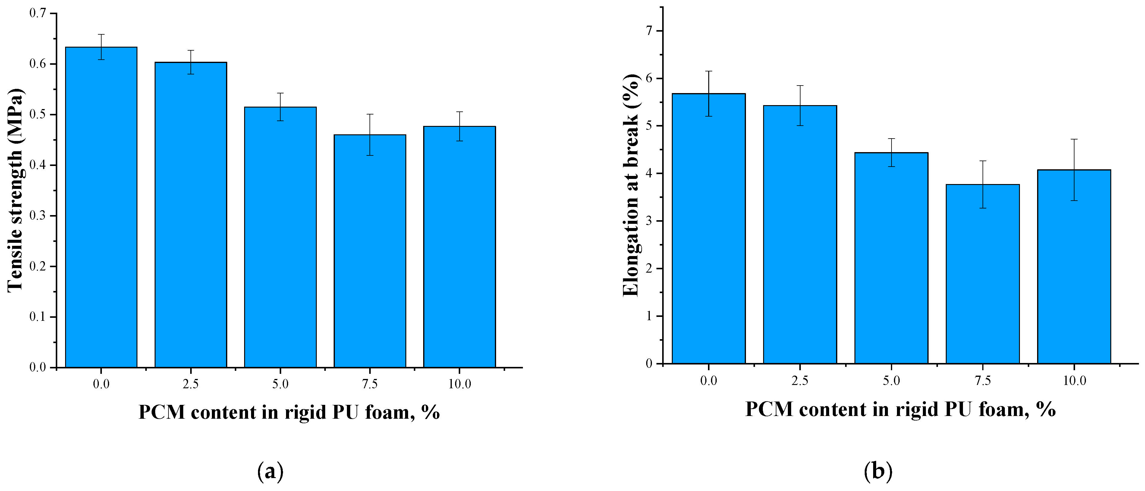
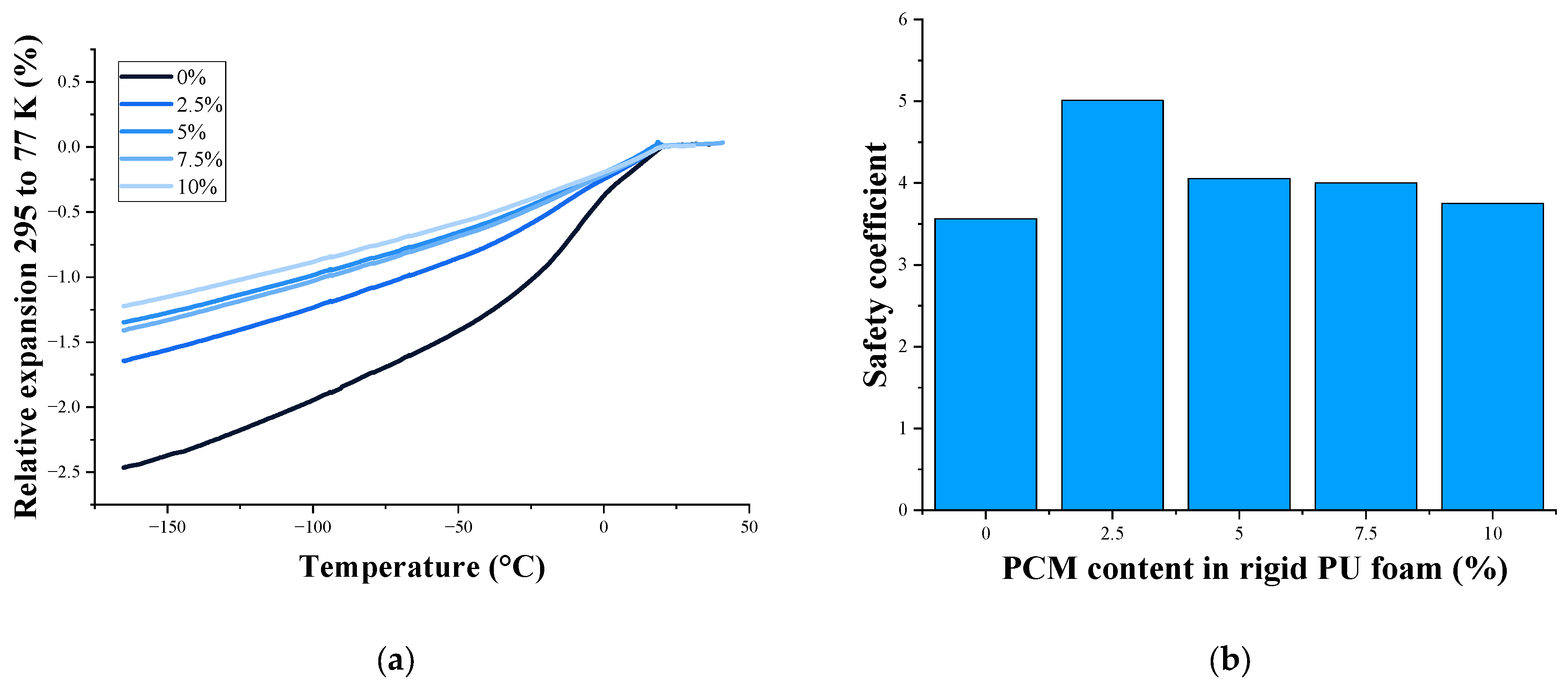
| PCM Content, % | Tensile Strength, MPa | Elongation at Break, % | Relative Expansion 295 to 77 K, % | Safety Coefficient |
|---|---|---|---|---|
| 0 | 0.60 ± 0.11 | 5.0 ± 0.9 | 1.57 | 3.2 |
| 2.5 | 0.46 ± 0.11 | 4.0 ± 0.9 | 1.30 | 3.0 |
| 5 | 0.48 ± 0.07 | 4.0 ± 0.4 | 1.37 | 2.9 |
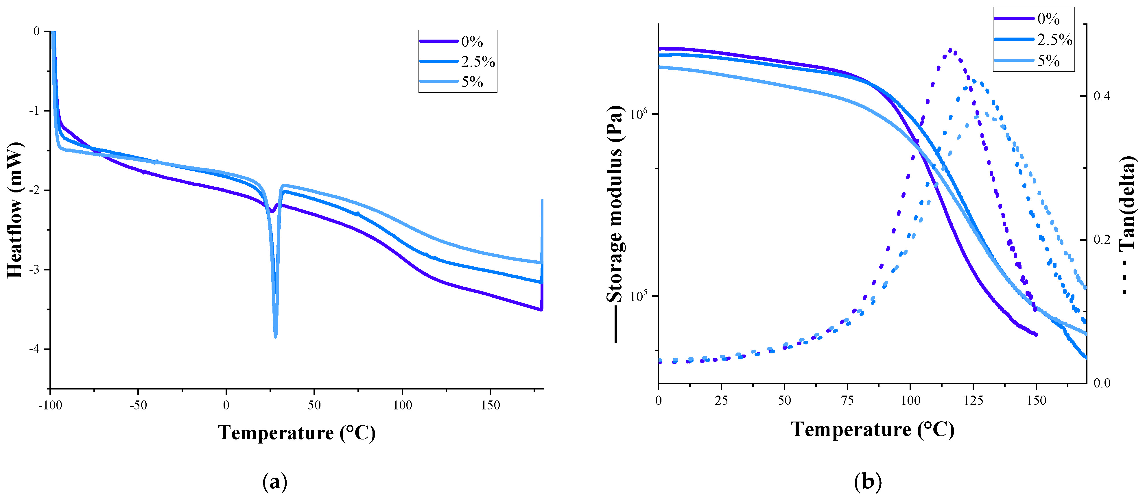
| PCM Content, % | Melting Temperature, °C | Freezing Temperature, °C | Heat of Fusion, J/g | Glass Transition Temperature, °C | |
|---|---|---|---|---|---|
| DSC | DMA | ||||
| 0 | 97.7 ± 1.8 | 116.0 ± 1.4 | |||
| 2.5 | 28.1 ± 0.8 | 18.1 ± 1.2 | 4.57 ± 0.5 | 101.9 ± 2.1 | 125.3 ± 2.1 |
| 5 | 28.0 ± 1.1 | 19.8 ± 0.9 | 6.51 ± 0.6 | 102.0 ± 2.0 | 129.2 ± 1.8 |
Disclaimer/Publisher’s Note: The statements, opinions and data contained in all publications are solely those of the individual author(s) and contributor(s) and not of MDPI and/or the editor(s). MDPI and/or the editor(s) disclaim responsibility for any injury to people or property resulting from any ideas, methods, instructions or products referred to in the content. |
© 2025 by the authors. Licensee MDPI, Basel, Switzerland. This article is an open access article distributed under the terms and conditions of the Creative Commons Attribution (CC BY) license (https://creativecommons.org/licenses/by/4.0/).
Share and Cite
Vevere, L.; Sture-Skela, B.; Yakushin, V.; Němeček, P.; Beneš, H.; Cabulis, U. Phase-Change Materials as Cryo-Shock Absorbers in Rigid Polyurethane Cryogenic Insulation Foams. Polymers 2025, 17, 729. https://doi.org/10.3390/polym17060729
Vevere L, Sture-Skela B, Yakushin V, Němeček P, Beneš H, Cabulis U. Phase-Change Materials as Cryo-Shock Absorbers in Rigid Polyurethane Cryogenic Insulation Foams. Polymers. 2025; 17(6):729. https://doi.org/10.3390/polym17060729
Chicago/Turabian StyleVevere, Laima, Beatrise Sture-Skela, Vladimir Yakushin, Pavel Němeček, Hynek Beneš, and Ugis Cabulis. 2025. "Phase-Change Materials as Cryo-Shock Absorbers in Rigid Polyurethane Cryogenic Insulation Foams" Polymers 17, no. 6: 729. https://doi.org/10.3390/polym17060729
APA StyleVevere, L., Sture-Skela, B., Yakushin, V., Němeček, P., Beneš, H., & Cabulis, U. (2025). Phase-Change Materials as Cryo-Shock Absorbers in Rigid Polyurethane Cryogenic Insulation Foams. Polymers, 17(6), 729. https://doi.org/10.3390/polym17060729