Article

Anion-Exchange Strategy for Ru/RuO2-Embedded N/S-Co-Doped Porous Carbon Composites for Electrochemical Nitrogen Fixation

1
The Soft2D Lab, State Key Laboratory of Metal Matrix Composites, Shanghai Key Laboratory of Electrical Insulation and Thermal Ageing, School of Chemistry and Chemical Engineering, Shanghai Jiao Tong University, 800 Dongchuan Road, Shanghai 200240, China
2
School of Materials, Shanghai Dianji University, 300 Shuihua Road, Pudong New Area District, Shanghai 201306, China
3
Power System Resources Environmental Technology Co., Ltd., 585 Changan North Road, Jiaxing 314399, China
4
Shanghai Nuclear Engineering Research and Design Institute Co., Ltd., 169 Tianlin Road, Xuhui District, Shanghai 200030, China
5
School of Chemical and Environmental Engineering, Shanghai Institute of Technology, 100 Haiquan Road, Shanghai 201418, China
6
Frontiers Science Center for Transformative Molecules, Zhang Jiang Institute for Advanced Study, Shanghai Jiao Tong University, 429 Zhangheng Road, Shanghai 201203, China
*
Authors to whom correspondence should be addressed.
Polymers 2025, 17(4), 543; https://doi.org/10.3390/polym17040543
Submission received: 26 January 2025 / Revised: 16 February 2025 / Accepted: 18 February 2025 / Published: 19 February 2025
(This article belongs to the Section Polymer Chemistry)

Abstract

:
Ionic porous polymers have been widely utilized efficiently to anchor various metal atoms for the preparation of metal-embedded heteroatom-doped porous carbon composites as the active materials for electrocatalytic applications. However, the rational design of the heteroatom and metal elements in HPC-based composites remains a significant challenge, due to the tendency of the aggregation of metal nanoparticles during pyrolysis. In this study, a nitrogen (N)- and sulfur (S)-enriched ionic covalent organic framework (iCOF) incorporating viologen and thieno[3,4-b] thiophene (TbT) was constructed via Zincke-type polycondensation. The synthesized iCOF possesses a crystalline porous structure with a pore size of 3.05 nm, a low optical band gap of 1.88 eV, and superior ionic conductivity of 10−2.672 S cm−1 at 333 K, confirming the ionic and conjugated nature of our novel iCOF. By applying the iCOF as the precursor, a ruthenium and ruthenium(IV) oxide (Ru/RuO2) nanoparticle-embedded N/S-co-doped porous carbon composite (NSPC-Ru) was prepared by using a two-step sequence of anion-exchange and pyrolysis processes. In the electrochemical nitrogen reduction reaction (eNRR) application, the NSPC-Ru achieves an impressive NH3 yield rate of 32.0 μg h−1 mg−1 and a Faradaic efficiency of 13.2% at −0.34 V vs. RHE. Thus, this innovative approach proposes a new route for the design of iCOF-derived metal-embedded porous carbon composites for enhanced NRR performance.

1. Introduction

Ammonia is one of the most essential chemical products and has been widely used in the fields of agricultural fertilizers, industrial chemicals, and energy carriers globally. Owing to the chemical inertness of nitrogen molecules, the traditional industrial technology for producing ammonia is the Haber–Bosch process, which combines nitrogen (N2) and hydrogen (H2) to form ammonia (NH3); however, it suffers from a low conversion efficiency of ~10–15%, harsh reaction conditions with high temperature and pressure, and serious pollution [1,2]. The electrocatalytic nitrogen reduction reaction (eNRR) has attracted more attention in recent years due to its mild operation at ambient temperature and pressure without emitting carbon dioxide, offering a renewable and eco-friendly alternative for ammonia production when it combines green electronic sources (solar, wind, and tidal energy) for power [3,4]. The electrocatalyst is the key component in the eNRR system, which is utilized for the construction of ammonia-producing electrochemical cells with high efficiency and stability. Many metals have been applied for the eNRR with good NH3 yield. The modification of metals can improve NRR performance via defect engineering, heteroatom doping, and the optimization of the electronic structure of the catalysts [5,6,7]. Currently, various carbon materials, like graphene, carbon nanotube, and porous carbon, have been used as the conductive supports to prepare carbon composites, confirming a promising approach to the design of electrocatalysts. Furthermore, the intrinsic electronic properties of carbon materials could be effectively adjusted by the incorporation of different heteroatoms, including N, S, boron (B), and phosphorus (P), into the skeleton of carbons, resulting in their enhanced electrocatalytic activity in the NRR [8,9,10,11]. Unfortunately, the tendency of the aggregation of metal nanoparticles would severely reduce the exposure of the active site of electrocatalysts, resulting in their limited electrocatalytic application. Thus, the rational design of metal/porous carbon composites with a uniform distribution of metal atoms and nanoparticles would be highly desirable for NRR applications.
Porous polymer-derived carbons are highly structured with large surface areas, making them ideal supports for electrocatalysts [12,13,14,15]. The mesoporous structure of porous polymer allows porous polymer-derived carbons to effectively host active nanoparticles. Moreover, heteroatoms can be incorporated into the framework of porous carbons by using various heteroatom-containing molecules as the building blocks. Covalent organic frameworks (COFs), introduced by Yaghi et al. in 2005, are a kind of crystalline porous polymers linked by reversible covalent bonds [16]. COFs possessing defined porous structures and high specific surface areas have been applied as precursors for the construction of different porous carbon materials. However, most COFs have been constructed from neutral building blocks, limiting their interactions with metal ions; therefore, nanosized metal nanoparticles are formed to aggregate easily during high-temperature pyrolysis [17,18,19]. Recently, ionic COFs (iCOFs) are the ideal precursors for the construction of metal/porous carbon composites. iCOFs can be tailored as either anionic or cationic by incorporating ionic monomers or modifying neutral COFs post-synthesis. Their well-organized porous channels facilitate efficient ion transport, enabling counter-charged ions to move selectively and rapidly. This controlled ion conduction is crucial to energy-related applications. In particular, cation–π interactions, where cations interact with π-electron-rich systems like graphene, play a significant role in enhancing charge transport and stability, making them highly relevant to electrochemical processes [20,21]. Conventional approaches to synthesizing iCOFs typically involve either preparing ionic building blocks or post-functionalizing COFs with ionic groups. These methods often demand complex organic reactions and exhibit low reaction conversion efficiency [22,23,24,25]. To date, the direct synthesis of iCOFs from ionic linkages remains a significant challenge. More importantly, the exploitation of these iCOFs for the preparation of metal/porous carbon composites and their electrocatalytic applications have still rarely been addressed.
Viologens, 4,4′-bipyridinium complexes, are a series of ionic conjugated molecules with rich redox chemistry. Many viologen-based iCOFs have been effectively created via one-step Zincke reaction synthesis [26,27,28]. In this work, we present a novel viologen-based iCOF-Cl containing TbT as the building block, in which viologen and TbT were used as the N and S sources. The as-prepared iCOF-Cl shows a crystalline structure with a pore size of 3.05 nm, a low band gap of 1.88 eV, and ionic conductivity of 10−2.672 S cm−1 at 333 K. After anchoring [Ru(CN)6]4− complexes onto the iCOF-Cl by the ion-exchange method, the iCOF-Ru could be turned into an NSPC-Ru with a uniform distribution of Ru/RuO2 nanoparticles via a pyrolysis treatment. As the electrocatalyst, the NSPC-Ru exhibited excellent electrochemical NRR performance, including an NH3 yield rate of 32.0 μg h−1 mg−1 and a Faradaic efficiency of 13.2% at −0.34 V vs. RHE. This proof-of-concept study provides a solid foundation to develop metal-embedded heteroatom-doped porous carbon composites for electrochemical NRR applications.

2. Materials and Methods

2.1. Materials

2,4-Dinitrochloro benzene, thieno[3,2-b]thiophene, N-bromosuccinimide (NBS), dimethyl formamide (DMF), palladium tetrakis(triphenyl)phosphine (9.2% (Pd) RG), ethanol (≥99.7% AR), tetrahydrofuran (99% RG), hexane (97% AR), acetone (99.5% HPLC), dichloromethane (≥99.5% AR), chloroform (≥99% AR), 4,4′-bipyridine (98% RG), 1-chloro-2,4-dinitrobenzene (98% RG), nitrogen (N2) (99.99% AR; Air Liquefied Group), argon (Ar), potassium sulphate (K2SO4), ammonium sulfate ((NH4)2SO4), salicylic acid, sodium citrate, sodium hypochlorite (NaClO), and sodium nitroprusside dihydrate (Na2[Fe(CN)5NO]·2H2O) were used. None of the above-mentioned reagents required post-treatment before use.

2.2. Instruments

Nuclear magnetic resonance (NMR) spectra in liquid phase were captured by using a Brucker AVANCE III HD (500 MHz) spectrometer, with tetramethylsilane serving as the internal reference. All chemical shifts are reported in ppm relative to the signals corresponding to the residual non-deuterated solvents (D2O, δ = 4.97 ppm; DMSO-d6, δ = 2.50 ppm; CDCl3, δ = 7.26 ppm). Coupling constant values (J) are given in hertz (Hz), and multiplicity is abbreviated in the following way: s (singlet), d (doublet), t (triplet), and splitting patterns that were not easily interpretable were labeled as multiplet (m). Mass spectrometry via MALDI-TOF was conducted by using an Autoflex Speed TOF/TOF Matrix-assisted laser desorption ionization time-of-flight mass spectrometer. Fourier transform infrared (FT-IR) spectroscopy was carried out by using a spectra 100 spectrometer from Perkin Elmer, Inc., Springfield, IL, USA. Measurements on AXIS Ultra DLD were conducted for XPS analysis. The thermal stability of all samples in a nitrogen atmosphere was investigated by performing TGA on a Discovery TGA550 thermogravimetric analyzer. A S 2150 Hitachi Corp (Japan) was used for SEM analysis. HRTEM images were obtained by using a FEI Sirion, 200. UV–vis measurements were taken at room temperature by using a Lamda-950. The UPS spectra were obtained by using an ESCALAB250Xi instrument (from Thermo Fisher Scientific, Waltham, MA, USA) with a monochromatic He light source (21.22 eV).

2.3. Preparation Procedure

Preparation of 2,5-dibromothieno[3,2-b] thiophene (Th-Br): The synthesis of Th-Br was carried out according to previously reported methods [29]. To a well-stirred solution of thieno[3,2-b] thiophene (TbT) (3.5 g, 25 mmol) in CHCl3 (75 mL), NBS (8.9 g, 50 mmol) dissolved in DMF (50 mL) was added dropwise at 0 °C in the absence of light. The mixture was then allowed to warm slowly to room temperature. After stirring for 12 h, the reaction was quenched with ice, and the aqueous phase was extracted three times with DCM. The combined organic layers were washed several times with brine and dried over MgSO4, and the solvent was removed under reduced pressure to give pale yellow flakes of Th-Br. Yield: 7.0 g (94%). The product should be stored at −20 °C in a refrigerator to prevent decomposition into a black solid; 1H NMR (500 MHz, DMSO-d6, δ): 7.60 (s, 2H); 13C NMR (101 MHz, DMSO-d6, δ): 138.6, 123.4, 113.5; MALDI-TOF m/z: [M + H]+ calcd. for C6H2Br2S2, 297.79; found, 297.48.
Preparation of 2,5-di(pyridin-4-yl) thieno[3,2-b] thiophene (ThBiPy): The synthesis of ThBiPy was carried out according to previously reported methods with some modifications [30]. A 250 mL oven-dried two-necked round-bottom flask was cooled in a nitrogen atmosphere and charged with Th-Br (2.0 g, 6.71 mmol), 4-pyridinylboronic acid (2.47 g, 20.13 mmol), Pd (PPh3)4 (0.38 g, 0.335 mmol), powdered NaOH (1.51 g, 26.84 mmol), and 100 mL of a toluene/EtOH/H2O mixture (3:2:1 v/v). The reaction mixture was heated to reflux in a nitrogen atmosphere for 2–3 days. The completion of the reaction was indicated by a color change from yellow to dark brown and confirmed by TLC analysis. The reaction mixture was then cooled to room temperature, and the solvents were removed under reduced pressure. The solid residue was extracted with CH2Cl2 and washed with a brine solution. The organic phase was dried over anhydrous Na2SO4 and concentrated in vacuo. The pure product was isolated by silica gel column chromatography by using a CH2Cl2/EA/1–5% MeOH mixture as the eluent, yielding ThBiPy as an orange solid. Yield: 1.53 g (77%); 1H NMR (500 MHz, DMSO-d6, δ): 7.71 (d, 4H), 8.28 (s, 2H), 8.63 (d, 4H); 13C NMR (500 MHz, DMSO-d6, δ): 151.0, 144.8, 131.8, 129.2, 121.6, 119.9; MALDI-TOF m/z: [M + H]+ calcd for, 294.39; found, 294.13.
Synthesis of 4,4′-(thieno[3,2-b] thiophene-2,5-diyl)) bis(1-(2,4-Dinitrophenyl)-4,4′-bipyridilium dichloride (Zincke-ThBiPy): The synthesis of Zincke-ThBiPy was carried out according to previously reported methods [31]. ThBiPy (40 mmol) and 2,4-dinitrochlorobenzene (100 mmol) were refluxed in ethanol (250 mL) for 16 h. After cooling, the precipitate was filtered and washed with acetone to obtain Zincke-ThBiPy. Yield: 90%. 1H NMR (400 MHz, D2O, δ): 8.86 (d, 2H), 8.47 (d, 2H), 8.19 (d, 2H), 8.94 (d, 4H), 9.31 (d, 4H), 8.50 (s, 2H). MALDI-TOF m/z: [M − Cl]+ calcd for C28H16N6O2S22, 628.59; found, 628.03.
Preparation of ionic two-dimensional covalent organic framework (iCOF-Cl): The ionic 2D-COF was prepared by using according to a method reported previously, but the reported method failed to achieve the 2D-COF, while we acquired the material with some modifications to the method [26]. An EtOH/water (5:5 v/v) mixture of 1,3,5-tris(4-aminophenyl) benzene (0.5 mmol, 0.175 g) and Zincke-ThBiPy was degassed by three freeze–pump–thaw cycles in a sealed tube (25 mL). The tube was kept in the oven for three days, with the temperature being maintained at 100 °C, and subsequently cooled to room temperature. The orange powder formed was washed with ethanol twenty times to purify the product and dried. The remaining solid product was then immersed in acetone overnight and then dried in oven at 60 °C to obtain the iCOF-Cl.
Preparation of ionic two-dimensional COF covered with [Ru(CN)6]4−: In a standard anion-exchange process, 1.0 g of iCOF-Cl was first dispersed in 10 mL of water and subjected to 30 min of ultrasonication to ensure even distribution. An aqueous solution of K4[Ru(CN)6] (10 mg in 5 mL of water) was then gradually added to the dispersion while stirring. This mixture was stirred at room temperature for 24 h. After this period, 5 mL of the dispersion was filtered, and the remaining powder was returned to the solution, with another portion of K4[Ru(CN)6]solution being added slowly. This cycle was repeated daily for seven days to achieve complete anion exchange. Following the final filtration, the product was washed three times with deionized water and freeze-dried to yield the [Ru(CN)6]4−-exchanged iCOF-Cl, designated as iCOF-Ru. This thorough process ensures effective anion exchange and results in a stable and functionalized material.
Preparation of Ru-RuO2-anchored NPSC-Ru by pyrolysis: The as-prepared iCOF-Ru was subjected to high temperature at 900 °C for 2 h, with the temperature rising at a rate of 10 °C per minute, resulting in the final NPSC-Ru product.

3. Results

The synthesis route to the iCOF-Cl is given in Figure 1a. The key intermediate of 2,5-di(pyridin-4-yl) thieno[3,2-b] thiophene (ThBiPy) was synthesized through a two-step procedure. First, a Suzuki cross-coupling reaction between pyridin-4-ylboronic acid and 2,5-dibromothieno[3,2-b] thiophene yielded the π-conjugated precursor. Subsequently, the resulting compound underwent a Zincke reaction with 1-chloro-2,4-dinitrobenzene to produce Zincke-ThBiPy in the yield of 90%. Then, Zincke-ThBiPy was reacted with tris(4-aminophenyl) benzene (TAPB) to form the ionic covalent organic framework iCOF-Cl in the mixture of ethanol/water (v:v = 5:5) under solvothermal conditions at 100 °C for three days. After cooling to room temperature, the resulting iCOF-Cl was thoroughly washed with EtOH to remove any residual reactants and was vacuum-dried overnight to obtain a brown powder. Finally, the obtained powder was soaked in acetone overnight and filtered to obtain the iCOF-Cl. The intermediates and monomers were thoroughly characterized by using nuclear magnetic resonance (1H NMR and 13C NMR), and matrix-assisted laser desorption/ionization time-of-flight (MALDI-TOF) mass spectroscopy (Figures S1–S6).
The as-prepared iCOF-Cl was verified through Fourier transform infrared spectroscopy (FT-IR), Raman spectroscopy, and X-ray photoelectron spectroscopy (XPS). In Figure 1b, the peak at 1332 cm−1 in TAPB is attributed to the stretching vibration of the C-N bond of aniline, while the characteristic signal of the nitro group appears at 1541 cm−1. However, these two peaks disappeared in the iCOF-Cl. The absorption bands at 832, 1606, and 1628 cm−1 in the FT-IR spectrum of the iCOF-Cl can be ascribed to the C-H out-of-plane bending vibration of aromatic group, the C=N stretching vibration of pyridinium salt, and the C=C stretching vibration of the aromatic group, respectively, suggesting the successful coupling of TAPB and Zincke-ThBiPy. The chemical state of the elemental components in the iCOF-Cl was further characterized by XPS analysis (Table S1). As illustrated in Figure S7, both the iCOF-Cl and Zincke-ThBiPy XPS survey spectra show distinct peaks corresponding to the elements of carbon (C), nitrogen (N), chlorine (Cl), and sulfur (S), verifying the presence of these elements in the materials. In the high-resolution S 2p spectrum, Zincke-ThBiPy reveals two predominant peaks at around 163.8 and 165.0 eV, attributed to the binding energies of the S 2p3/2 and S 2p1/2 states in the thieno[3,2-b] thiophene, respectively (Figure S7c). Compared with that of Zincke-ThBiPy, the S 2p spectrum of the iCOF-Cl exhibits a shift towards lower binding energy, suggesting the electron donating effect of 1,3,5-triphenylbenzene [32]. Additionally, both Zincke-ThBiPy and the iCOF-Cl exhibit similar spectrum profiles in the high resolution of C 1s and Cl 2p [33]. In contrast, the N 1s XPS spectra of the iCOF-Cl and Zincke-ThBiPy highlight key differences in nitrogen chemical environments that stem from their unique synthesis processes and structural frameworks. For the iCOF-Cl, the N 1s spectrum shows three primary peaks at 398 eV, 400 eV, and 402 eV, corresponding to sp2-hybridized nitrogen (C–N), quaternary or pyridinium nitrogen (C–N+), and partially reduced nitro groups (NO2). In contrast, Zincke-ThBiPy exhibits similar peaks for C–N at 398 eV and C–N+ at 400 eV, but a distinct feature emerges at 406 eV, attributed to fully oxidized nitro groups (NO2), indicating monomers [34]. These shifts in binding energy indicate changes in the chemical environment and electron density of the atoms, showing their incorporation into a more complex covalent framework [35]. The XPS data confirm the successful formation of the iCOF-Cl with new interactions and coordination environments.
The Wide-Angle X-ray Scattering (WAXS) pattern of the iCOF-Cl reveals distinct peaks at 2θ = 2.2°, 3.6°, and 4.2°, corresponding to the (100), (110), and (200) facets, respectively (Figure 2a), which differ significantly from the XRD patterns of the monomer precursors (Figure S8). A broad signal at 2θ = 25.1° corresponds to the (001) facet, indicating an interlayer distance of 3.6 Å, which is characteristic of structures formed through π–π stacking interactions between the aromatic layers. The structural simulations of the iCOF-Cl in the tetragonal system in AB-stacking mode yielded PXRD patterns that align well with the experimental data, confirming the AB-stacking configuration as the predominant arrangement. Notably, the experimental peaks around 2θ = 10.8° and 14.2° also match the simulated AB-stacking pattern, further validating this structural model. In contrast, the simulated patterns in AA-stacking mode show significant deviations in peak positions and intensities, ruling out this configuration. The combined analysis of WAXS and PXRD patterns confirms the AB-stacked tetragonal structure of the iCOF-Cl, characterized by a well-defined interlayer spacing of 3.6 Å and distinct stacking interactions. These structural features are critical to understanding the material’s crystalline framework and potential applications. To elucidate the morphological attributes and structural composition of the prepared iCOF-Cl material, scanning electron microscopy (SEM) was employed. Figure S9 reveals an asymmetrical bulk morphology with a size of over 1 micrometer. Transmission electron microscopy (TEM) provides direct visual evidence of the crystalline structure (Figure 2c and Figure S10). In Figure 2d, the lattice fringes with a spacing of 0.36 nm confirm the ordered arrangement, corresponding to the reflections (001) observed in the XRD pattern. This consistency between the 0.36 nm d-spacing in both XRD and high-resolution TEM data indicates that the periodic layers detected in XRD match the electron diffraction periodicity. These results collectively reinforce the conclusion that the iCOF-Cl has a well-defined crystalline structure with π–π stacking interactions between the aromatic layers.
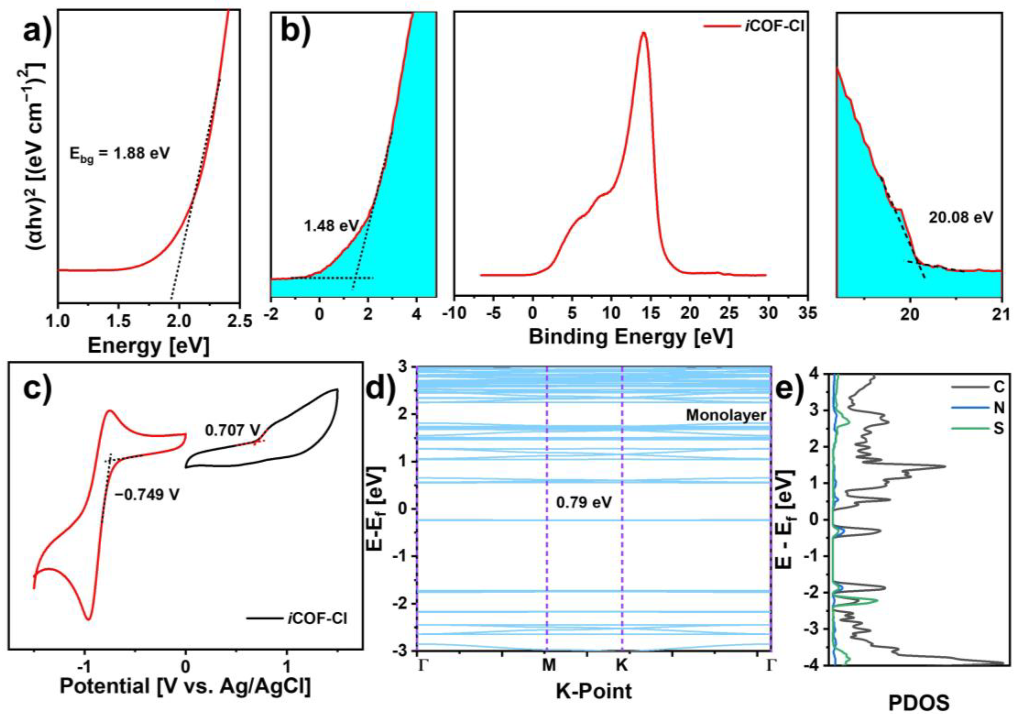
The optical properties of the powder iCOF-Cl were evaluated by using UV–vis measurements. The absorption peak around 302 nm is ascribed to the π–π transition, while the signal at 462 nm is attributed to the n–π transition of Py+-ThBiPy, due to the intramolecular charge transfer from the donor of ThBiPy to the acceptor of Py+ (Figure S11). The broad absorption region from 300 to 1000 nm is attributed to the strong intermolecular interactions in the solid state of the iCOF-Cl. The optical bandgap (Ebg) of the iCOF-Cl was calculated to be 1.88 eV via the Tauc plot derived from the UV–vis spectrum (Figure 3a). The electronic structure of iCOF-Cl was further characterized by ultraviolet photoelectron spectroscopy (UPS) (Figure 3b). By subtracting the measured UPS width from the excitation energy (HeI, 21.22 eV), the valence band (Evb) of the iCOF-Cl was calculated to be −4.66 eV. Subsequently, the conduction band (Ecb) was calculated to be −2.78 eV by using the equation Ecb = Ebg + Evb [36]. The electronic structure of the iCOF-Cl was further evaluated by cyclic voltammetry (CV) measurements in nitrogen-saturated acetonitrile (Figure S12). The iCOF-Cl exhibits an irreversible oxidation peak at 0.707 eV and a one-electron reversible reduction peak at −0.749 eV. Based on the onset reduction potentials, the LUMO energy level of the iCOF-Cl was determined to be −5.06 eV. Its HOMO energy level was calculated to be −3.18 eV with the equation HOMO = LUMO + Ebg. These electrochemical energy levels are similar to those of the optical measurements.
To gain deep insights into its electronic properties, the band structure and partial density of states (PDOS) of the iCOF-Cl were calculated by the DFT method (Figure 3d,e). The top of the conduction band and the bottom of the valence band in the monolayer are both flat, suggesting the effective mass of the charge carriers injected into these bands, demonstrating the semiconducting nature of the iCOF-Cl. The band structure analysis for the monolayer reveals a band gap of 0.79 eV. Regarding the effect of AB-stacking, the band gaps of the iCOF-Cl were narrowed to 0.60 eV, owing to the partial interlayer π−π interaction (Figure S13) [37]. The PDOS plot also demonstrates that C and S atoms contributed to the valence band, suggesting that the thieno[3,2-b] thiophene units contributed to the valence band, while the C atoms predominantly contributed to the conduction band, indicating that the 2p orbitals of the carbon atoms play a significant role in determining the electronic properties. This detailed understanding of the band structure and PDOS highlights the potential of the iCOF-Cl for various electronic and optoelectronic applications.
The ionic conductivity of iCOF-Cl as the pellet samples was evaluated by using a 0.5 M 1-butyl-3-methylimidazolium tetrafluoroborate (BMIMBF4) electrolyte through electrochemical impedance spectroscopy (EIS) measurements (Figure S14). The Nyquist plots from EIS reveal sharp semicircular arcs, indicative of ionic resistance within the material. With the increase in temperature, the radius of the semicircle decreases, suggesting enhanced ionic mobility at higher temperatures. In Figure S14b, the Arrhenius plot of log conductivity (log [S cm−1]) versus the reciprocal of temperature (1000/T) demonstrates the linear relationship between temperature and ion conductivity, confirming its thermally activated ionic conduction ability. The highest ionic conductivity could reach 10−2.672 S cm−1 at 333 K (60 °C). Additionally, the effect of relative humidity (RH) on the ionic conductivity of the iCOF-Cl was also evaluated. The ionic conductivity of the iCOF-Cl increases with the increase in RH. The ionic conductivity of the iCOF-Cl is 5.02 × 10⁻³ S cm−1 at 57% RH, and it can reach 1.219 × 10⁻² S cm−1 at 98% RH (Figure S14c and Tables S2 and S3). This phenomenon is attributed to the formation of hydrogen bonds by the adsorption of water molecules, facilitating the enhanced mobility of charge carriers within the material [38]. These findings underscore the potential of the iCOF-Cl as a highly conductive material under varying environmental conditions, making it suitable for advanced electrochemical applications.
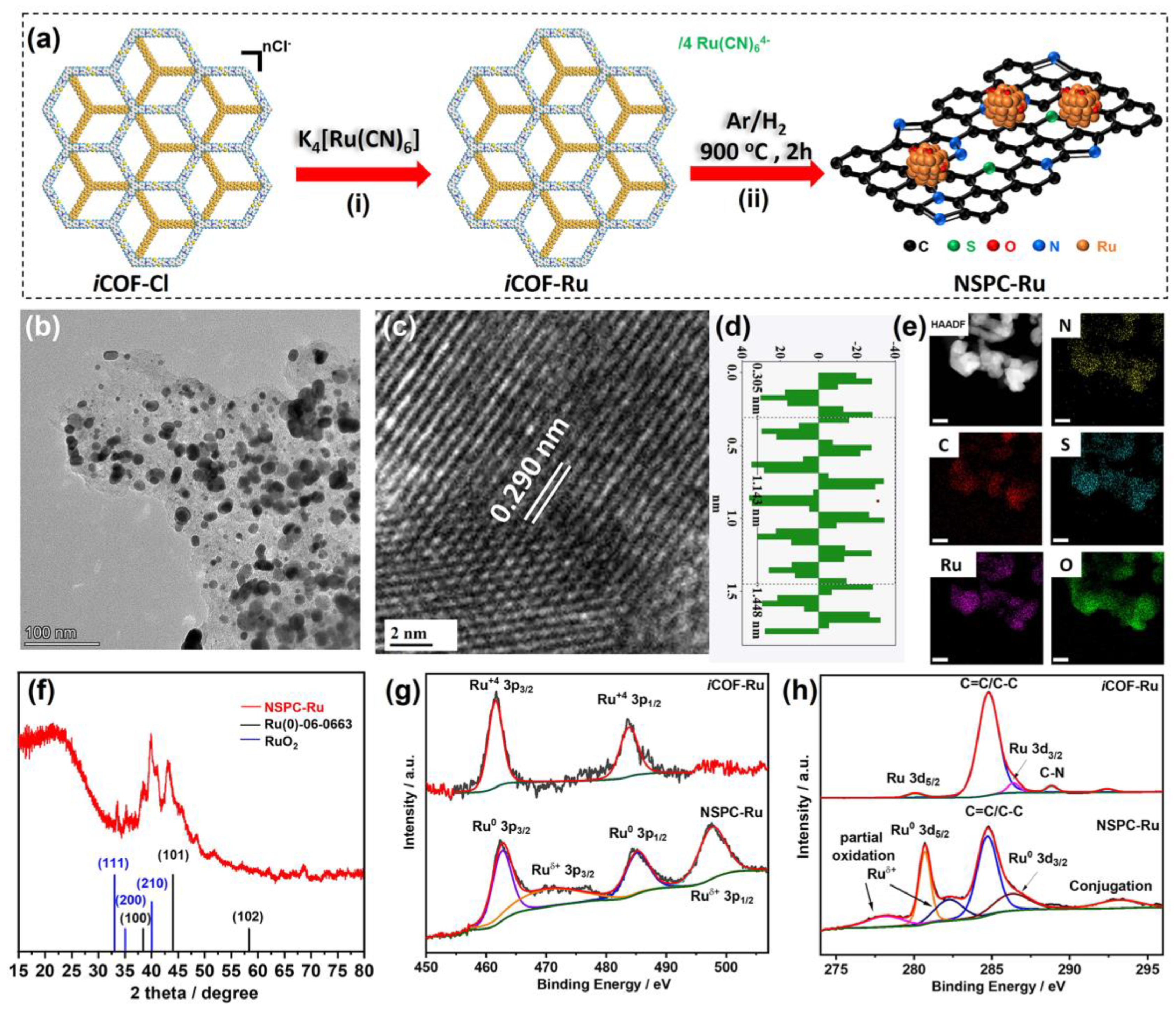
Owing to its charge conjugated framework and high residual carbon yield, this iCOF-Cl could be applied as the precursor for the construction of metal/porous carbon composites [39,40]. As illustrated in Figure 4a, the chloride anions (Cl) in the iCOF-Cl are replaced by hexacyanoruthenate anions ([Ru(CN)6]4−) by a typical anion-exchange procedure, resulting in the construction of the iCOF-Ru with the incorporation of Ru species within the COF. The High-Angle Annular Dark-Field Scanning Transmission Electron Microscopy (HAADF-STEM) image clearly shows the white spots corresponding to the ruthenium (Ru) element due to its higher atomic number (Figure S15), evidencing the presence of Ru species within the matrix of the COF. The uniform distribution of Ru species in the iCOF-Ru was confirmed by Energy-Dispersive X-ray Spectroscopy (EDS) elemental mapping. Owing to its high residual carbon yield (Figure S16), the iCOF-Ru was subjected to pyrolysis at 900 °C for 2 h. This high-temperature treatment reduces the ruthenium anions to ruthenium nanoparticles to yield a N/S-co-doped porous carbon material embedded with Ru/RuO2 nanoparticles (NSPC-Ru). The microstructure of the prepared NSPC-Ru was investigated by using TEM, as shown in Figure 4b. The TEM image reveals that the as-prepared NSPC-Ru nanosheets exhibit a uniform hexagonal morphology (Figure 4c), and the HRTEM image displays lattice fringes with a d-spacing of 0.290 nm for metallic Ru0 (Figure 4d and Figure S17). Figure 4e depicts the EDS mapping of the NSPC-Ru, revealing the uniform distribution of C, N, Ru, and S throughout the structure. The XRD pattern of the NSPC-Ru (Figure 4f) shows prominent peaks at 2θ = 38.6°, 44.1°, and 58.4°, which correspond to the characteristic peaks of Ru0 metal (JCPDS card No. 06-0663), while these peaks at 2θ = 32.1°, 35.1°, and 40.0° are attributed to the characteristic peaks of RuO2 (JCPDS card No. 43-1027). These analyses confirm the successful synthesis of the NSPC-Ru with Ru/RuO2 nanoparticles [41]. The valence states of N, C, S, and Ru elements in the iCOF-Ru and NSPC-Ru were further evaluated by XPS measurements (Figure S18). For the iCOF-Ru, the high-resolution N 1s XPS spectrum reveals the presence of multiple nitrogen environments, indicating variations in chemical bonding. The deconvoluted peaks show contributions from C–N at 398.7 eV, C–N+ at 400.3 eV, quaternary nitrogen at 401.2 eV, and reduced NO2 at 403.5 eV. In contrast, the NSPC-Ru exhibits distinct nitrogen species, including pyridinic nitrogen, pyrrolic nitrogen, and quaternary nitrogen, at 398.5 eV, 399.8 eV, and 401.1 eV, respectively (Figure S18b) [34]. These differences in nitrogen configurations suggest variations in the electronic structure and surface chemistry between the two materials, modulating electron density, adsorption properties, and interaction with reactants. In the high-resolution S 2p spectrum, the iCOF-Ru exhibits two predominant peaks corresponding to the binding energies of S 2p3/2 at 163.8 eV and S 2p1/2 at 165.0 eV, which can be attributed to sulfur species in the thieno[3,2-b]thiophene framework (Figure S18c) [32]. In comparison, the S 2p spectrum of the NSPC-Ru displays a more pronounced sulfur peak, indicating higher sulfur content. In Figure 4g, the Ru 3p XPS spectrum of the iCOF-Ru shows two peaks at 461.6 eV and 484 eV, corresponding to the Ru 3p3/2 and Ru 3p1/2 of the high oxidation state of Ru4+ species, respectively, suggesting the successful incorporation of [Ru(CN)6]4− in the iCOF-Ru. Additionally, two Ru 3d peaks at 280.1 eV (Ru 3d5/2) and 285.8 eV (Ru 3d3/2) are also detected (Figure 4h). Moreover, the C 1s spectra reveal that the dominant peak at 284.8 eV, corresponding to C=C bonds, demonstrates the characteristic of sp2 hybridized carbon in the iCOF-Ru. These results confirm that the [Ru(CN)6]4− anions are loaded in the framework of the iCOF without damage to the polymeric structure. For the NSPC-Ru, slight red shifts in the binding energies of both the Ru 3p and Ru 3d spectra are observed, suggesting the successful integration of Ru0 into the carbon framework. Additionally, the NSPC-Ru exhibits two new peaks in the Ru 3p spectra (469.8 eV and 497.4 eV) and in the Ru 3d spectra (278.0 eV and 282.3 eV), which can be attributed to surface interactions with oxygen. These peaks may also originate from interfacial interactions with carbon, possibly influenced by sulfur and nitrogen [42]. Moreover, additional peaks in Ru4+ 3p and Ru 3d can be ascribed to RuO2 in the skeleton of porous carbon [43]. These results demonstrate the successful synthesis of Ru/RuO2 nanoparticle-embedded N/S-co-doped porous carbon.
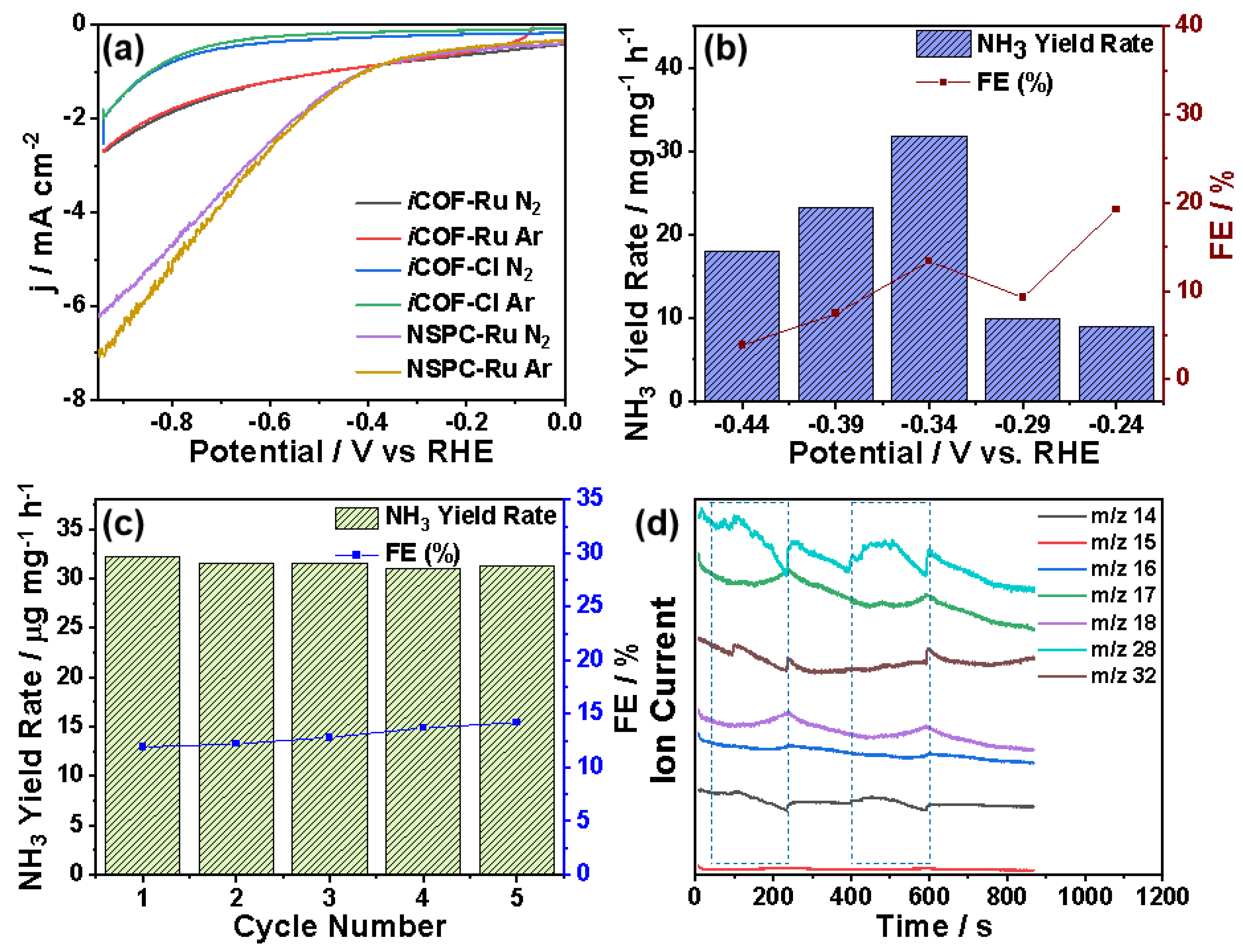
Owing to the porous structure with uniform distribution of Ru/RuO2 nanoparticles, the electrochemical nitrogen reduction reaction (eNRR) of the NSPC-Ru test was thoroughly evaluated by using a three-electrode setup in 0.1 M potassium sulfate (K2SO4) solutions (pH = 7.0) [44]. As illustrated in Figure S19a, the NSPC-Ru catalyst was loaded onto carbon paper, serving as the working electrode, with a Nafion 117 membrane separating it from the counter electrode. All electrode potentials were measured with a commercial Ag/AgCl reference electrode and standardized to the reversible hydrogen electrode (RHE) scale. Linear sweep voltammetry was performed in the Ar- and N2-saturated electrolytes comprising the samples, and the current density was increased with the increase in the negative potential. Compared with that under the Ar-saturated condition, the current density under the N2-saturated condition is more negative, suggesting the possible occurrence of NRRs in all samples (Figure 5a). For example, at −0.6 V vs. RHE, the current density of −2.80 mA cm−2 under the N2-saturated condition is higher than that (−2.46 mA cm−2) under the Ar-saturated condition. By using ammonium sulfate to establish the corresponding standard curve by UV–vis measurements, the product of NH3 was evaluated via the indophenols-blue method [45]. The product of the NRR is NH3, and N2H4 is not detectable in the electrolyte (Figures S20–S24). Figure 5b shows the NH3 yield rate and Faradaic efficiency (FE) of the NSPC-Ru in the applied potential range of −0.24–−0.44 V vs. RHE. At −0.34 V vs. RHE, the highest NH3 yield rate is 32.0 μg h−1 mg−1 with a corresponding FE of 13.2%, which is comparable to other reported works (Table S4). The cycle stability of the NSPC-Ru was carried out at −0.34 V vs. RHE. As shown in Figure 5c, the NH3 yield rates of the NSPC-Ru remain around 32.0 μg h−1 mg−1 over five consecutive eNRR cycles, and the values of FE have a slight incline over repeated cycles. This is further supported by Figure S21, indicating that the NSPC-Ru and the iCOF-Ru possess a higher electrochemically active surface area (ECSA) compared with the iCOF-Cl, as reflected by their larger Cdl values. A higher Cdl correlates with more active sites available for catalytic reactions, which is crucial to enhancing nitrogen reduction reaction (NRR) efficiency. Moreover, the NSPC-Ru demonstrated exceptional stability and durability, maintaining a steady current density over 15 h of continuous electrolysis, as seen in Figure S26b. On the other hand, the highest NH3 yield rate could reach 11.2 μg h−1 mg−1 for the iCOF-Ru at −0.29 V vs. RHE, with a much lower current density under the N2-saturated condition, as well as the Ar-saturated condition (Figure S27). These results demonstrate that the NSPC-Ru exhibits high electrochemical durability for nitrogen reduction. To further understand the catalytic activity of the NSPC-Ru, online differential electrochemical mass spectrometry (DEMS) measurements were conducted to monitor volatile intermediates (Figure S25) [46]. In the eNRR process, the primary detected species are nitrogen (N2, m/z = 28) and ammonia (NH3, m/z = 17, 18), indicating the successful conversion of nitrogen to ammonia. Although hydrazine (N2H4), a known intermediate, could theoretically be detected at m/z = 32 with fragments at m/z = 14, 15, and 16, it is not clearly observed in the data. This is likely due to its rapid conversion to ammonia, preventing its accumulation, or because its concentration is too low compared with nitrogen and ammonia. Additionally, fragmentation overlap with species like ammonia, water, and oxygen may obscure the hydrazine signals. The catalyst efficiently converts nitrogen to ammonia, bypassing or minimizing the stabilization of hydrazine as a long-lived intermediate, resulting in the detection of only the stable products (N2 and NH3). The synergistic electronic effect of Ru/RuO2 enhances catalytic performance by maximizing active site exposure, improving mass transport, and facilitating efficient electron transfer for N2 activation. Additionally, the highly ordered ionic pore channels in iCOF-based catalysts minimize transport resistance, ensuring a more efficient and uniform reaction environment. Unlike conventional COFs, iCOFs incorporate charged moieties within their framework, promoting selective ion transport and optimizing catalytic efficiency. Their structural precision and electrochemical stability make them highly suitable for applications requiring sustained performance under extreme conditions. These attributes collectively establish iCOFs as advanced catalytic materials for the nitrogen reduction reaction (NRR), where enhanced charge transport and ion mobility play a crucial role in improving reaction kinetics and selectivity [21,44].

4. Conclusions

The study of the thienothiophene-bridged viologen-based ionic covalent organic framework (iCOF-Cl) and its derivative (NSPC-Ru) highlights significant advancements in material synthesis and catalytic performance. The iCOF-Cl, synthesized by reacting tris(4-aminophenyl) benzene (TAPB) with Zincke-ThBiPy at 100 °C, was confirmed to have an AB-stacked structure with an optical band gap of 1.88 eV. The NSPC-Ru was subsequently synthesized by reducing Ru anions in the iCOF-Cl, achieving high crystallinity and the incorporation of Ru/RuO2 nanoparticles. The catalytic performance of the NSPC-Ru was evaluated for the electrocatalytic conversion of N2 to NH3 under ambient conditions. Experimental results demonstrated an NH3 yield rate of 32.0 μg mg−1 h−1 and a Faradaic efficiency of 13.2% at −0.34 V vs. RHE, with notable stability over repeated cycles. Moreover, the catalyst exhibited remarkable stability and durability, sustaining a steady current density over 15 h of continuous electrolysis. This study establishes a robust platform for the further exploration and development of metal-embedded heteroatom-doped porous carbon sheets and the potential of the NSPC-Ru as an exceptionally efficient electrocatalyst for advanced electrocatalytic systems.

Supplementary Materials

The following supporting information can be downloaded at: https://www.mdpi.com/article/10.3390/polym17040543/s1, Figures S1–S5: 1H NMR and 13C NMR, Figure S6: MALDI-TOF, Figure S7: XPS analysis, Figure S8: XRD spectra, Figures S9 and S10: SEM and TEM images, Figure S11: UV–vis spectrum, Figure S12: CV analysis, Figure S13: Calculated band structure, Figure S14: Nyquist plots, Figure S15: HAADF-STEM, Figure S16: TGA analysis, Figure S17: HRTEM analysis, Figure S18: XPS analysis, Figures S19–S24: eNNR tests, Figure S25: online DEMS analysis, Figure S26: (a) LSV curves of NSPC-Ru before and after long-term stability test. (b) Long-term stability of NSPC-Ru. Figure S27: (a) Chronoamperometric curves for NSPC-Ru after every one hour at 5 different voltages. (b) UV–vis absorption spectra. (c) NH3 yield rates for iCOF-Ru for eNRR. Table S1: XPS analysis, Table S2: Conductivity results, Table S3: Comparison performance of conductivity, Table S4. Comparison of different catalysts in electrochemical nitrogen reduction reaction.

Author Contributions

Conceptualization, X.Z.; methodology, S.A.S.; software, X.Y. and S.H.; validation, Z.H., C.L. and M.Y.; formal analysis, S.A.S., X.Y., S.H. and J.H.; investigation, S.A.S., C.L. and F.Q.; resources, M.Y.; writing—original draft preparation, S.A.S.; writing—review and editing, F.Q. and X.Z.; visualization, Z.Z.; supervision, X.Z.; project administration, Z.Z. and X.Z.; funding acquisition, F.Q. and X.Z. All authors have read and agreed to the published version of the manuscript.

Funding

This work was financially supported by National Natural Science Foundation of China (NSFC: 52173205) and NSFC Young Scientists Fund (22208213, 22208210). F.Q. is thankful for the support from Shanghai Pujiang Program (2022PJD070). The computations in this paper were run on the π 2.0 cluster supported by the Center for High Performance Computing at Shanghai Jiao Tong University. We thank the support from the Instrumental Analysis Center of SJTU.

Institutional Review Board Statement

Not applicable.

Data Availability Statement

The data presented in this study are available upon request from the corresponding author.

Conflicts of Interest

Author Junbo Hou was employed by the company Power System Resources Environmental Technology Co. Ltd.; Author Zhenyu Zhang was employed by the company Shanghai Nuclear Engineering Research and Design Institute Co., Ltd. The remaining authors declare that the research was conducted in the absence of any commercial or financial relationships that could be construed as a potential conflict of interest.

References

  1. Kuriyama, S.; Arashiba, K.; Nakajima, K.; Matsuo, Y.; Tanaka, H.; Ishii, K.; Yoshizawa, K.; Nishibayashi, Y. Catalytic transformation of dinitrogen into ammonia and hydrazine by iron-dinitrogen complexes bearing pincer ligand. Nat. Commun. 2016, 7, 12181. [Google Scholar] [CrossRef] [PubMed]
  2. Kyriakou, V.; Garagounis, I.; Vourros, A.; Vasileiou, E.; Stoukides, M. An Electrochemical Haber-Bosch Process. Joule 2020, 4, 142–158. [Google Scholar] [CrossRef]
  3. Yu, X.; Han, P.; Wei, Z.; Huang, L.; Gu, Z.; Peng, S.; Ma, J.; Zheng, G. Boron-Doped Graphene for Electrocatalytic N2 Reduction. Joule 2018, 2, 1610–1622. [Google Scholar] [CrossRef]
  4. Ma, X.-L.; Liu, J.-C.; Xiao, H.; Li, J. Surface Single-Cluster Catalyst for N2-to-NH3 Thermal Conversion. J. Am. Chem. Soc. 2018, 140, 46–49. [Google Scholar] [CrossRef] [PubMed]
  5. Liu, S.; Wang, M.; Qian, T.; Ji, H.; Liu, J.; Yan, C. Facilitating nitrogen accessibility to boron-rich covalent organic frameworks via electrochemical excitation for efficient nitrogen fixation. Nat. Commun. 2019, 10, 3898. [Google Scholar] [CrossRef]
  6. Jiang, M.; Han, L.; Peng, P.; Hu, Y.; Xiong, Y.; Mi, C.; Tie, Z.; Xiang, Z.; Jin, Z. Quasi-Phthalocyanine Conjugated Covalent Organic Frameworks with Nitrogen-Coordinated Transition Metal Centers for High-Efficiency Electrocatalytic Ammonia Synthesis. Nano Lett. 2022, 22, 372–379. [Google Scholar] [CrossRef]
  7. Ohashi, K.; Iwase, K.; Harada, T.; Nakanishi, S.; Kamiya, K. Rational Design of Electrocatalysts Comprising Single-Atom-Modified Covalent Organic Frameworks for the N2 Reduction Reaction: A First-Principles Study. J. Phys. Chem. C 2021, 125, 10983–10990. [Google Scholar] [CrossRef]
  8. Song, P.; Wang, H.; Cao, X.; Liu, N.; Wang, Q.; Wang, R. Ambient Electrochemical N2 Reduction to NH3 on Nitrogen and Phosphorus Co-doped Porous Carbon with Trace Iron in Alkaline Electrolytes. Chem. Electro. Chem. 2020, 7, 212–216. [Google Scholar] [CrossRef]
  9. Chen, W.; Ge, C.; Li, J.T.; Beckham, J.L.; Yuan, Z.; Wyss, K.M.; Advincula, P.A.; Eddy, L.; Kittrell, C.; Chen, J.; et al. Heteroatom-Doped Flash Graphene. ACS Nano 2022, 16, 6646–6656. [Google Scholar] [CrossRef] [PubMed]
  10. Tian, J.; Bai, H.; Cai, J.; Xiao, Y.; Talifu, D.; Abulizi, A. Efficient electrochemical reduction of nitrogen from biomass doped boron and nitrogen under ambient conditions. Surf. Interface Anal. 2023, 55, 176–183. [Google Scholar] [CrossRef]
  11. Zang, W.; Yang, T.; Zou, H.; Xi, S.; Zhang, H.; Liu, X.; Kou, Z.; Du, Y.; Feng, Y.P.; Shen, L.; et al. Copper Single Atoms Anchored in Porous Nitrogen-Doped Carbon as Efficient pH-Universal Catalysts for the Nitrogen Reduction Reaction. ACS Catal. 2019, 9, 10166–10173. [Google Scholar] [CrossRef]
  12. Huang, Y.-B.; Pachfule, P.; Sun, J.-K.; Xu, Q. From covalent–organic frameworks to hierarchically porous B-doped carbons: A molten-salt approach. J. Mater. Chem. A 2016, 4, 4273–4279. [Google Scholar] [CrossRef]
  13. Romero, J.; Rodriguez-San-Miguel, D.; Ribera, A.; Mas-Ballesté, R.; Otero, T.F.; Manet, I.; Licio, F.; Abellán, G.; Zamora, F.; Coronado, E. Metal-functionalized covalent organic frameworks as precursors of supercapacitive porous N-doped graphene. J. Mater. Chem. A 2017, 5, 4343–4351. [Google Scholar] [CrossRef]
  14. Chen, L.; Zhang, L.; Chen, Z.; Liu, H.; Luque, R.; Li, Y. A covalent organic framework-based route to the in situ encapsulation of metal nanoparticles in N-rich hollow carbon spheres. Chem. Sci. 2016, 7, 6015–6020. [Google Scholar] [CrossRef]
  15. Xu, Q.; Tang, Y.; Zhang, X.; Oshima, Y.; Chen, Q.; Jiang, D. Template Conversion of Covalent Organic Frameworks into 2D Conducting Nanocarbons for Catalyzing Oxygen Reduction Reaction. Adv. Mater. 2018, 30, 1706330. [Google Scholar] [CrossRef]
  16. Côté, A.P.; Benin, A.I.; Ockwig, N.W.; O’Keeffe, M.; Matzger, A.J.; Yaghi, O.M. Porous, Crystalline, Covalent Organic Frameworks. Science 2005, 310, 1166–1170. [Google Scholar] [CrossRef] [PubMed]
  17. Wang, L.; Yang, Y.; Liang, H.; Wu, N.; Peng, X.; Wang, L.; Song, Y. A novel N,S-rich COF and its derived hollow N,S-doped carbon@Pd nanorods for electrochemical detection of Hg2+ and paracetamol. J. Hazard. Mater. 2021, 409, 124528. [Google Scholar] [CrossRef]
  18. Xu, Q.; Tang, Y.; Zhai, L.; Chen, Q.; Jiang, D. Pyrolysis of covalent organic frameworks: A general strategy for template converting conventional skeletons into conducting microporous carbons for high-performance energy storage. Chem. Commun. 2017, 53, 11690–11693. [Google Scholar] [CrossRef] [PubMed]
  19. Ding, J.; Guo, D.; Hu, A.; Yang, X.; Shen, K.; Chen, L.; Li, Y. Resisting metal aggregation in pyrolysis of MOFs towards high-density metal nanocatalysts for efficient hydrazine assisted hydrogen production. Nano Res. 2023, 16, 6067–6075. [Google Scholar] [CrossRef]
  20. Feng, J.D.; Zhang, W.D.; Gu, Z.G. Covalent organic frameworks for electrocatalysis: Design, applications and perspective. Chem. Plus Chem. 2024, 89, e202400069. [Google Scholar] [CrossRef] [PubMed]
  21. Kim, Y.; Li, C.; Huang, J.; Yuan, Y.; Tian, Y.; Zhang, W. Ionic Covalent Organic Framework Solid-State Electrolytes. Adv. Mater. 2024, 36, 2407761. [Google Scholar] [CrossRef] [PubMed]
  22. Das, G.; Sharma, S.K.; Prakasam, T.; Gándara, F.; Mathew, R.; Alkhatib, N.; Saleh, N.i.; Pasricha, R.; Olsen, J.-C.; Baias, M.; et al. A polyrotaxanated covalent organic network based on viologen and cucurbit[7]uril. Commun. Chem. 2019, 2, 106. [Google Scholar] [CrossRef]
  23. Mitra, S.; Kandambeth, S.; Biswal, B.P.; Khayum, M.A.; Choudhury, C.K.; Mehta, M.; Kaur, G.; Banerjee, S.; Prabhune, A.; Verma, S.; et al. Self-Exfoliated Guanidinium-Based Ionic Covalent Organic Nanosheets (iCONs). J. Am. Chem. Soc. 2016, 138, 2823–2828. [Google Scholar] [CrossRef] [PubMed]
  24. Li, Z.; Li, H.; Guan, X.; Tang, J.; Yusran, Y.; Li, Z.; Xue, M.; Fang, Q.; Yan, Y.; Valtchev, V.; et al. Three-Dimensional Ionic Covalent Organic Frameworks for Rapid, Reversible, and Selective Ion Exchange. J. Am. Chem. Soc. 2017, 139, 17771–17774. [Google Scholar] [CrossRef] [PubMed]
  25. Yu, S.-B.; Lyu, H.; Tian, J.; Wang, H.; Zhang, D.-W.; Liu, Y.; Li, Z.-T. A polycationic covalent organic framework: A robust adsorbent for anionic dye pollutants. Polym. Chem. 2016, 7, 3392–3397. [Google Scholar] [CrossRef]
  26. Das, G.; Skorjanc, T.; Sharma, S.K.; Gándara, F.; Lusi, M.; Shankar Rao, D.S.; Vimala, S.; Krishna Prasad, S.; Raya, J.; Han, D.S.; et al. Viologen-Based Conjugated Covalent Organic Networks via Zincke Reaction. J. Am. Chem. Soc. 2017, 139, 9558–9565. [Google Scholar] [CrossRef]
  27. Samanta, P.; Chandra, P.; Dutta, S.; Desai, A.V.; Ghosh, S.K. Chemically stable ionic viologen-organic network: An efficient scavenger of toxic oxo-anions from water. Chem. Sci. 2018, 9, 7874–7881. [Google Scholar] [CrossRef]
  28. Fu, Y.; Li, Y.; Zhang, W.; Luo, C.; Jiang, L.; Ma, H. Ionic Covalent Organic Framework: What Does the Unique Ionic Site Bring to Us? Chem. Res. Chin. Univ. 2022, 38, 296–309. [Google Scholar] [CrossRef]
  29. Wang, X.; Zhang, F.; Gao, J.; Fu, Y.; Zhao, W.; Tang, R.; Zhang, W.; Zhuang, X.; Feng, X. Synthesis and Properties of C2h-Symmetric BN-Heteroacenes Tailored through Aromatic Central Cores. J. Org. Chem. 2015, 80, 10127–10133. [Google Scholar] [CrossRef] [PubMed]
  30. Scott, H.S.; Shivanna, M.; Bajpai, A.; Madden, D.G.; Chen, K.-J.; Pham, T.; Forrest, K.A.; Hogan, A.; Space, B.; Perry Iv, J.J.; et al. Highly Selective Separation of C2H2 from CO2 by a New Dichromate-Based Hybrid Ultramicroporous Material. ACS Appl. Mater. Interfaces 2017, 9, 33395–33400. [Google Scholar] [CrossRef]
  31. Alesanco, Y.; Viñuales, A.; Palenzuela, J.; Odriozola, I.; Cabañero, G.; Rodriguez, J.; Tena-Zaera, R. Multicolor Electrochromics: Rainbow-Like Devices. ACS Appl. Mater. Interfaces 2016, 8, 14795–14801. [Google Scholar] [CrossRef] [PubMed]
  32. Liu, Y.; Wang, M.; Dong, C.; Yu, H.; Lu, Y.; Huang, X.; Paasch, S.; Brunner, E.; Heine, T.; Song, F.; et al. A thienyl-benzodithiophene-based two-dimensional conjugated covalent organic framework for fast photothermal conversion. J. Polym. Sci. 2023, 61, 1843–1848. [Google Scholar] [CrossRef]
  33. Vattikuti, S.V.P.; Reddy, P.A.K.; Shim, J.; Byon, C. Synthesis of vanadium-pentoxide-supported graphitic carbon nitride heterostructure and studied their hydrogen evolution activity under solar light. J. Mater. Sci. Mater. Electron. 2018, 29, 18760–18770. [Google Scholar] [CrossRef]
  34. Jhariat, P.; Warrier, A.; Sasmal, A.; Das, S.; Sarfudeen, S.; Kumari, P.; Nayak, A.K.; Panda, T. Reticular synthesis of two-dimensional ionic covalent organic networks as metal-free bifunctional electrocatalysts for oxygen reduction and evolution reactions. Nanoscale 2024, 16, 5665–5673. [Google Scholar] [CrossRef]
  35. Zhang, S.; Mei, D.; Li, K.; Yan, B. β-Ketoenamine covalent organic frameworks with abundant carboxyl groups for the efficient removal of malachite green in actual water environments. Sep. Purif. Technol. 2024, 348, 127812. [Google Scholar] [CrossRef]
  36. Chen, Z.; Chen, Y.; Zhao, Y.; Qiu, F.; Jiang, K.; Huang, S.; Ke, C.; Zhu, J.; Tranca, D.; Zhuang, X. B/N-Enriched Semi-Conductive Polymer Film for Micro-Supercapacitors with AC Line-Filtering Performance. Langmuir 2021, 37, 2523–2531. [Google Scholar] [CrossRef] [PubMed]
  37. Feng, B.; Chen, X.; Yan, P.; Huang, S.; Lu, C.; Ji, H.; Zhu, J.; Yang, Z.; Cao, K.; Zhuang, X. Isomeric Dual-Pore Two-Dimensional Covalent Organic Frameworks. J. Am. Chem. Soc. 2023, 145, 26871–26882. [Google Scholar] [CrossRef] [PubMed]
  38. Zhang, F.-M.; Dong, L.-Z.; Qin, J.-S.; Guan, W.; Liu, J.; Li, S.-L.; Lu, M.; Lan, Y.-Q.; Su, Z.-M.; Zhou, H.-C. Effect of Imidazole Arrangements on Proton-Conductivity in Metal–Organic Frameworks. J. Am. Chem. Soc. 2017, 139, 6183–6189. [Google Scholar] [CrossRef] [PubMed]
  39. Liu, Y.; Wang, H.; Liu, F.; Kang, J.; Qiu, F.; Ke, C.; Huang, Y.; Han, S.; Zhang, F.; Zhuang, X. Self-Assembly Approach Towards MoS2-Embedded Hierarchical Porous Carbons for Enhanced Electrocatalytic Hydrogen Evolution. Chem. Eur. J. 2021, 27, 2155–2164. [Google Scholar] [CrossRef]
  40. Tu, K.; Tranca, D.; Rodríguez-Hernández, F.; Jiang, K.; Huang, S.; Zheng, Q.; Chen, M.-X.; Lu, C.; Su, Y.; Chen, Z.; et al. A Novel Heterostructure Based on RuMo Nanoalloys and N-doped Carbon as an Efficient Electrocatalyst for the Hydrogen Evolution Reaction. Adv. Mater. 2020, 32, 2005433. [Google Scholar] [CrossRef]
  41. Gao, X.; Chen, J.; Sun, X.; Wu, B.; Li, B.; Ning, Z.; Li, J.; Wang, N. Ru/RuO2 Nanoparticle Composites with N-Doped Reduced Graphene Oxide as Electrocatalysts for Hydrogen and Oxygen Evolution. ACS Appl. Nano Mater. 2020, 3, 12269–12277. [Google Scholar] [CrossRef]
  42. Wang, X.; Li, D.; Dai, J.; Xue, Q.; Yang, C.; Xia, L.; Qi, X.; Bao, B.; Yang, S.; Xu, Y.; et al. Blocking Metal Nanocluster Growth through Ligand Coordination and Subsequent Polymerization: The Case of Ruthenium Nanoclusters as Robust Hydrogen Evolution Electrocatalysts. Small 2024, 20, 2309176. [Google Scholar] [CrossRef] [PubMed]
  43. Cao, Y.; Zhang, H.; Liu, K.; Zhang, Q.; Chen, K.-J. Biowaste-Derived Bimetallic Ru–MoOx Catalyst for the Direct Hydrogenation of Furfural to Tetrahydrofurfuryl Alcohol. ACS Sustain. Chem. Eng. 2019, 7, 12858–12866. [Google Scholar] [CrossRef]
  44. Han, Z.; Tranca, D.; Rodríguez-Hernández, F.; Jiang, K.; Zhang, J.; He, M.; Wang, F.; Han, S.; Wu, P.; Zhuang, X. Embedding Ru Clusters and Single Atoms into Perovskite Oxide Boosts Nitrogen Fixation and Affords Ultrahigh Ammonia Yield Rate. Small 2023, 19, 2208102. [Google Scholar] [CrossRef] [PubMed]
  45. Han, Z.; Huang, S.; Zhang, J.; Wang, F.; Han, S.; Wu, P.; He, M.; Zhuang, X. Single Ru–N4 Site-Embedded Porous Carbons for Electrocatalytic Nitrogen Reduction. ACS Appl. Mater. Interfaces 2023, 15, 13025–13032. [Google Scholar] [CrossRef] [PubMed]
  46. Wang, H.; Huang, J.; Cai, J.; Wei, Y.; Cao, A.; Liu, B.; Lu, S. In Situ/Operando Methods for Understanding Electrocatalytic Nitrate Reduction Reaction. Small Methods 2023, 7, 2300169. [Google Scholar] [CrossRef] [PubMed]
Figure 1. (a) Synthesis of iCOF-Cl: (i) reflux, N2, 2 days; (ii) reflux, N2, 16 h; and (iii) 100 °C, N2, 3 days; thieno[3,2-b] thiophene unit, pyridinium and counter anion present orange, blue and red color, respectively. (b) FT-IR spectra of TAPB, Zincke-ThBiPy, and iCOF-Cl. (c) N 1s spectra of iCOF-Cl and Zincke-ThBiPy.
Polymers 17 00543 g001
Figure 2. (a) Experimental WAXS pattern of iCOF-Cl and calculated PXRD patterns for AA-stacking and AB-stacking. (b) A fragment of the layered structure shown for AB-stacked structure. (c) High-resolution TEM image of iCOF-Cl, the area of white breakpoint box shows its crystalline region for enlargement analysis. (d) Lattice fringe for iCOF-Cl.
Polymers 17 00543 g002
Figure 3. Optoelectronic properties of iCOF-Cl. (a) Tauc plot for iCOF-Cl. (b) UPS spectrum of iCOF-Cl. The edges of the UPS spectrum are given by the intersections of two dashed lines of the tangents and the baseline, from which the UPS width is determined. (c) CV curves of iCOF-Cl (calculated from corresponding onsets of redox waves referred to Fc/Fc+ set as −4.8 eV vs. vacuum). (d) Calculated band structure of iCOF-Cl for monolayer. (e) Projected density of states (PDOS) of iCOF-Cl.
Polymers 17 00543 g003
Figure 4. (a) Preparation of NSPC-Ru through anion-exchanging strategy: (i) aqueous solution of iCOF-Cl and [K4(Ru(CN6)] mixed for 7 days at r.t.; (ii) high-temperature treatment of iCOF-Ru at 900 °C. (b) HRTEM image of NSPC-Ru. (c) Lattice fringes for NSPC-Ru. (d) Line profile of lattice fringes. (e) EDS elemental mapping for NSPC-Ru, scale bar: 200 nm. (f) XRD pattern for NSPC-Ru compared with standard metallic Ru (JCPDS card No. 06-0663) and RuO2 (JCPDS card No. 43-1027). (g) XPS analysis of Ru 3p spectra of iCOF-Ru and NSPC-Ru, black color for raw data, red color for smooth data, dark green for baseline, violet color for Ru0 3p3/2, blue for Ru0 3p1/2, orange color for Ru&+ 3p3/2, cyan color for Ru&+ 3p1/2. (h) XPS analysis of C 1s and Ru 3d spectra of iCOF-Ru and NSPC-Ru, black color for raw data, red color for smooth data, dark green for baseline, blue for C=C/C-C, cyan for C-N, light green for Ru4+ 3d5/2, magenta for Ru4+ 3d3/2, violet color for Ru0 3d5/2, wine color for Ru0 3d3/2, orange for Ru&+.
Polymers 17 00543 g004
Figure 5. (a) LSV curves for iCOF-Ru, iCOF-Cl, and NSPC-Ru in Ar and N2. (b) FE and NH3 yield rates for NSPC-Ru for eNRR. (c) FE and NH3 yield rates for NSPC-Ru at potential of −0.34 V vs. RHE after five consecutive experiments. (d) In situ DEMS investigation: ion current responses of m/z signal in different time intervals relative to LSV curve.
Polymers 17 00543 g005
Disclaimer/Publisher’s Note: The statements, opinions and data contained in all publications are solely those of the individual author(s) and contributor(s) and not of MDPI and/or the editor(s). MDPI and/or the editor(s) disclaim responsibility for any injury to people or property resulting from any ideas, methods, instructions or products referred to in the content.