3.1. Morphological Analyses
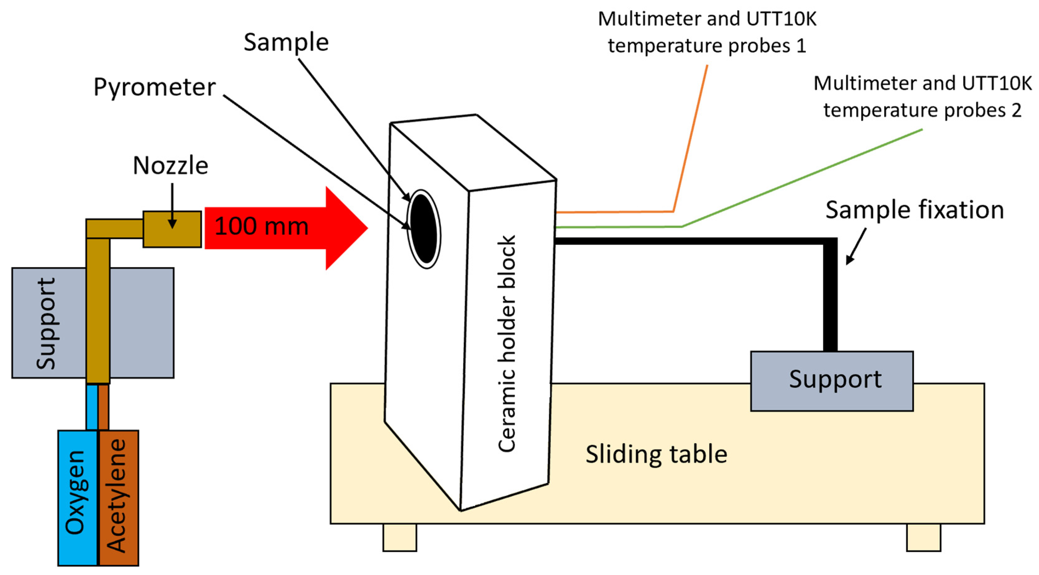
Visual inspection and morphology analysis, along with thickness measurements, were performed following the Oxyacetylene Test Bed (OTB) ablation tests. The loss of weight due to the ablation process was also evaluated.
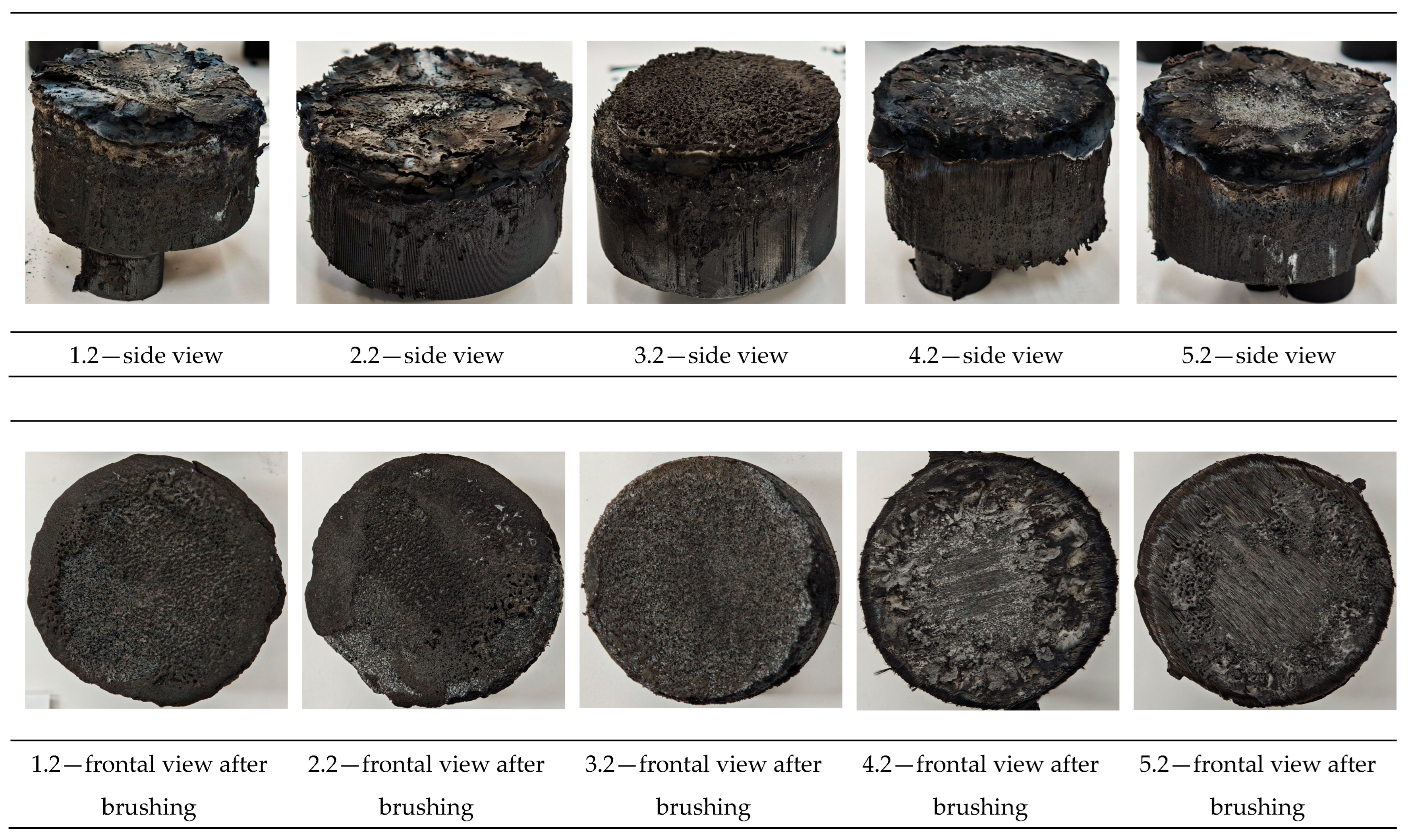
Figure 3 depicts images of the samples following OTB ablation testing, prior to and after char removal. The sample front faces can be seen to be covered with a carbon-rich char layer, with dark brown regions indicating that the expected oxidation had occurred. The visual observations indicated a mixed mechanism during ablation of dripping accompanied by charring. The brown color of the burnt surface of samples is potentially related to the presence of the metal hydroxides FR additives from the bulk thermoplastic, enhancing fire safety by reducing flammability and promoting self-extinguishment. The char layer acts as a barrier to heat transfer; its porous structure provides insulation and potentially can also re-radiate some of the absorbed heat. Then as the surface of the char layer erodes away through ablation, it carries away heat energy, further protecting the underlying material. Dissimilar to traditional ablative materials that develop a thick char layer, thermoplastic ablatives typically exhibit higher gas formation rates at lower surface temperatures and produce a comparatively thinner char layer.
The post-testing appearance of exposed surfaces of the samples was characterized by a wide and relatively broad eroded surface, while both 4 and 5 continuously reinforced configurations showed a confined central region, strongly confined under the plume of the impinging torch, revealing the fibers.
In the case of both samples of configuration 2, the 5 g of Al2O3 from the inner slot near the surface did not thermo-mechanically adhere to the beneath structural material, since the surface temperature achieved was well below its 2200 °C melting point; thus, it completely detached from the base material. A comparable behavior was observed on the configuration 1 surface-coated samples. The sample frontal view exhibits more pronounced detachment of the surface coating due to high thermal flux exposure for a longer time (60 s) compared to 30 s exposure time, indicating poor adhesion and embedded into the Onyx FR V0 melted layer adjacent to the bulk material of the Al2O3 powder layer. Likewise, cracking or debonding from the substrate was also attributed to the difference in coefficients of thermal expansion between the substrate and the coating. Once the coating was ablatively removed, it vanished to exert the protective function.
Referring to configuration 3, significant thermal erosion protection was observed on the 3.1 sample exposed for 30 s, given by the near-surface slot integrated CFRP laminate disk and especially by the 2D carbon weave. Nevertheless, the disk was completely removed on the 3.2 sample exposed for 60 s, since the CFRP disk was only integrated in the slot and no mechanical bonding was assured prior to OTB ablation testing. Configurations 4 and 5, carbon and glass, respectively, that were continuously reinforced, exhibit improved thermal behavior among all developed configurations. Both configurations were developed in order to assess the contribution of the additional continuous reinforcement phase to the thermal resistance and ablation performance of the newly developed 3D-printed TPS configurations, beyond the influence of the novel internal air chamber architectural concept. Carbon fibers have excellent thermal stability and can withstand very high temperatures (often above 3000 °C in inert atmospheres); nevertheless, when exposed to high heat, in the presence of oxygen carbon fibers can oxidize (burn), typically starting around 600 °C, oxidation leading to degradation, structure breakdown, and loss of mechanical strength. On the other hand, although glass fibers start to soften at high temperatures, typically around 800 °C, they do not readily ignite or burn and are considered non-combustible. The main component of glass, silica, is already in its highest oxidation state and, thus, does not react with oxygen, meaning it will not burn in a fire. Furthermore, although of thermoplastic nature, the matrix Onyx FR V0 embedding the fibers in different configurations (short carbon/short carbon with additional long continuous fiber reinforcement) is an FR blend. Thus, when exposed to very high temperatures, they are the first to undergo thermal degradation, melting, vaporization, or sublimation, followed by the fibers degradation. The reinforcement phase effect and its role in the thermoplastic composite burning process are, however, very complex, depending on the fiber type, its quantity, orientation, length, thermal conductivity, and size agent.
Nevertheless, it is a fact that both continuously reinforced configurations showed higher thermal stability, improved ablative behavior, lower mass loss, and lower recession rate. The 10% by volume of short carbon fiber content and additional continuous fiber frontal reinforcement (configurations 4 and 5) not only provide high strength and stiffness, but also their morphology and distribution create a thermal conductivity anisotropy that plays an important role in quickly dissipating heat away from the ablation surface in one direction (e.g., along fibers) while restricting heat flow in other directions (e.g., into the material). This helped to prevent excessive heat buildup at the surface and reduced damage. The burning mechanisms differed between bulk thermoplastic and continuously reinforced composite configurations due to fiber–matrix interactions and heat transfer dynamics. In composite materials, the interface between the matrix and the reinforcing fibers played a critical role in their combustion behavior. The reinforcing fibers influenced heat conduction anisotropically, depending on their orientation, thereby affecting the internal temperature distribution. In the initial stage, melting and dripping of the thermoplastic matrix occurred. The carbon-rich char layer formed on the sample surfaces acted as a thermal barrier but was locally eroded by flame abrasion at the center of the front surface, particularly in configurations 4 and 5, exposing the matrix–reinforcement interface. A comparison between the two reinforced configurations indicates that the type of reinforcement plays a key role in the thermal protection and ablation processes. The continuous carbon fiber reinforcement phase exhibits a higher thermal conductivity when compared to glass fibers, assuring an efficient directional heat dissipation (e.g., along the fiber alignment), simultaneously restricting heat flow in other directions (through bulk material).
Moreover, following visual analysis, the recession rate and thickness mass loss measurements were performed succeeding char layer removal by brushing the surface of tested samples.
3.2. Cross-Sectional Examination and Recession Rate
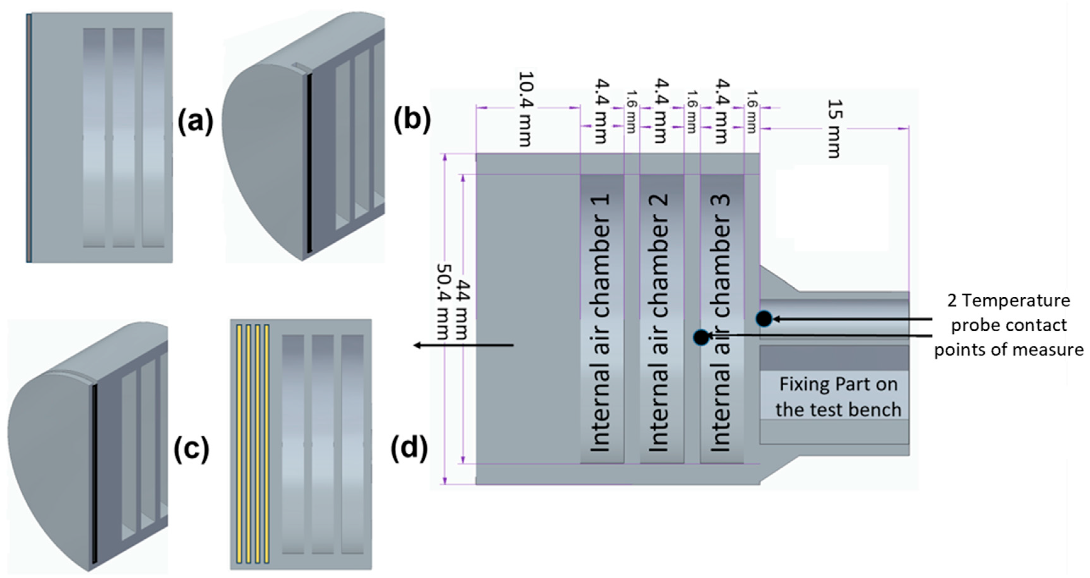
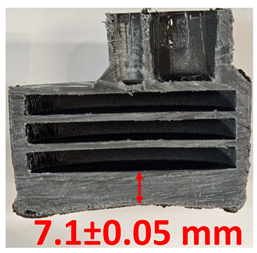
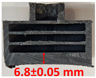
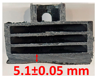
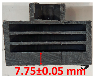
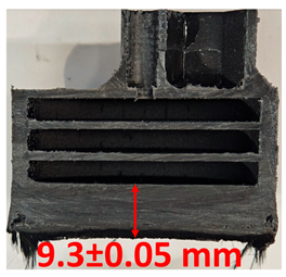
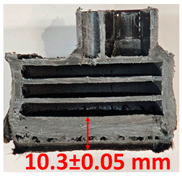
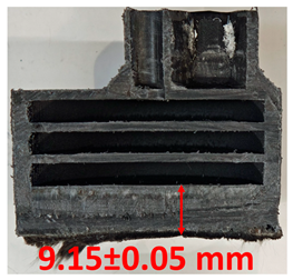
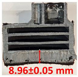
Surface images, cross-sectional views, and post-burning thickness measurements (of the front wall before the first air chamber, as shown in
Table 2) of all tested samples were analyzed after the char layer was removed by brushing. It is important to stress that the inner walls separating the three air chambers were not affected, keeping their dimensions and structural integrity for all samples exposed to 30 and 60 s. The ablation removes material through vaporization or erosion. Cross-sectional examinations indicate a thickness loss for all tested configurations when increasing the flame time exposure from 30 s to 60 s, except for continuously carbon-reinforced configuration 4. This specific configuration revealed the formation of delamination cracks and pores at the interface between the fiber layers and the bulk Onyx FR V0 material, visible but in a lower amount also in configuration 5 (continuously glass-fiber-reinforced). The solidification cracks and trapped porosity observed at the interface result from a complex interplay of mechanisms involving solid, liquid, and vapor phases, including melting, oxidation, volatilization, and liquid flow. Specifically, the formation of these features is attributed to reactive volatile compounds produced in the decomposition zone and to water vapor generated near the rear face of the composite, both of which tend to migrate through the char layer toward the heated surface. In the case of both continuously reinforced configurations, during ablation, as the matrix degrades and then erodes, the continuous reinforcements are directly exposed to the hot stream and, thus, their temperature rises. As a result, the fibers endothermically react with the hot gas stream acting as a heat sink. During the process, part of the gases was trapped due to the composite’s low gas permeability, resulting in increased internal pressure and expansion of the material; thus, the thickness increases with time exposure for configuration 4. Such a behavior is very common in many charring ablators. By contrast, in all the other configurations, this frontal reinforcement fiber barrier is not present, the porous nature of the char layer allowing the gases to easily flow through it.
Furthermore, reinforced configurations 4 and 5 exhibit pronounced anisotropy and heterogeneity, particularly with respect to their thermal conductivity properties. The carbon fiber thermal conductivity in the direction of the parallel fiber axis is about 250 times that of the matrix (bulk material Onyx FRV0), leading to a higher heat transfer into the fiber layers and bulk material interfaces and increased volumetric ablation of the composite and internal gas generation. The carbon fibers high thermal conductivity tended to increase the in-depth penetration of the charring phenomena, and consequently, the pyrolysis gases could not escape due to the low permeability barrier impediment; thus, pores developed into cracks, and further on, the fibers suffered severe, in-depth debonding or pull-out from the matrix. The decreased pore amount observed in configuration 5 was attributed to the lower thermal conductivity of glass fibers when compared to carbon fibers.
The lack of pore formation within 1, 2, and 3 configurations, where the additional surface coating or slot-filled materials were eliminated in the first stages during the ablation tests, is due to the front thermal barrier elimination and freedom for volatile compounds pyrolysis gas to flow through the pores of the char to the ablation surface and contribute to the surface energy balance, potentially reducing the effective convective heat flow acting on the TPS.
The rate of material recession caused by ablation was calculated by measuring the loss in specimen thickness over the duration of thermal exposure. Thickness measurements were made using a Mitutoyo CD-P15P (Mitutoyo Corporation, Kawasaki, Japan) model digital vernier caliper with a measuring range of 0–150 mm and a measuring accuracy of 0.01 mm. Following testing, only the thickness of the unreacted material was taken into account. As a result, the recession measurement captures the extent of the reaction layer’s progression into the virgin material and does not include the surface char thickness. Recession is an indicator of the time duration of thermal protection, so low values are desirable.
Table 2 summarizes the results of recession rates and cross-section views of all post-tested samples.
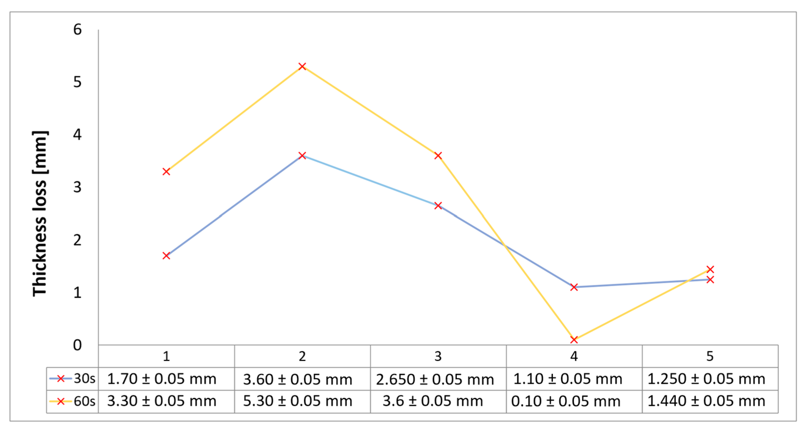
With respect to the recession rate, it can be observed that both reinforced configurations 4 and 5 displayed the lowest values, with a slightly lower value for the carbon-reinforced configuration 4, indicating an increase in thermal resistance when compared to the other tested configurations. The lower recession rates are potentially attributed to both continuous carbon glass reinforcements and short/chopped carbon fibers from the Onyx FR V0 matrix that ensure an anisotropic thermal conductivity quickly dissipates heat away from the ablation surface in the fiber direction while restricting heat flow into the bulk material. In the case of carbon continuously reinforced configuration 4, the higher thermal conductivity of carbon fibers leads to an increased internal pressure and expansion of the material due to pore front formation at the interface between the fiber layers and the bulk Onyx FR V0 material. On the other hand, continuous glass fiber reinforcing the front wall of configuration 5 not only contributes to a higher structural stiffness but also through its very low thermal conductivity, acts like a frontal barrier for thermal protection due to its lower thermal conductivity. Consequently, although configuration 5 graphically indicates a higher thickness reduction when compared to carbon-reinforced configuration 4 for 60 s exposure time, glass fiber reinforced configuration 4 exhibits a higher thermal and abrasion resistance. The glass frontal layer appears denser and less impacted by volumetric expansion caused by pores, likely due to its lower thermal conductivity and greater abrasion resistance. Likewise, glass fiber thermal softening followed by degradation typically starts around 800 °C, while for carbon fibers the oxidation process begins earlier at around 600 °C. Nevertheless, overall, the above observations are consistent with the thickness losses reported in
Figure 4.
Both continuous fiber reinforcements ensure a front thermal barrier during ablation tests.
Configuration 1 exhibits a slightly higher thickness loss when compared to the continuous fiber reinforced configuration and a significantly lower thickness loss when compared to configurations 2 and 3, potentially attributed to only local removal of the Al2O3 surface coating layer during ablation. In the case of configurations 2 and 3, the removal of the slot-filled materials (Al2O3 powder and, respectively, CFRP composite laminate disk) during the ablation tests led to a significant effect on thickness and mass loss.
3.3. Mass Loss Assessment
The relative ablative loss of mass (expressed as a percentage) was determined by analyzing the changes in the weight of the examined samples before and after the heat resistance tests. Mass loss was assessed after 30 s and 60 s exposure time, following char layer elimination by brushing, using a Kern PLJ 510-3M (KERN & SOHN GmbH, Balingen, Germany), model analytical balance providing a ±0.001 g precision. Mass loss values provided an indication of the time duration that ablatives can offer effective thermal protection. The results of mass loss measurements for the all tested configurations are indicated in
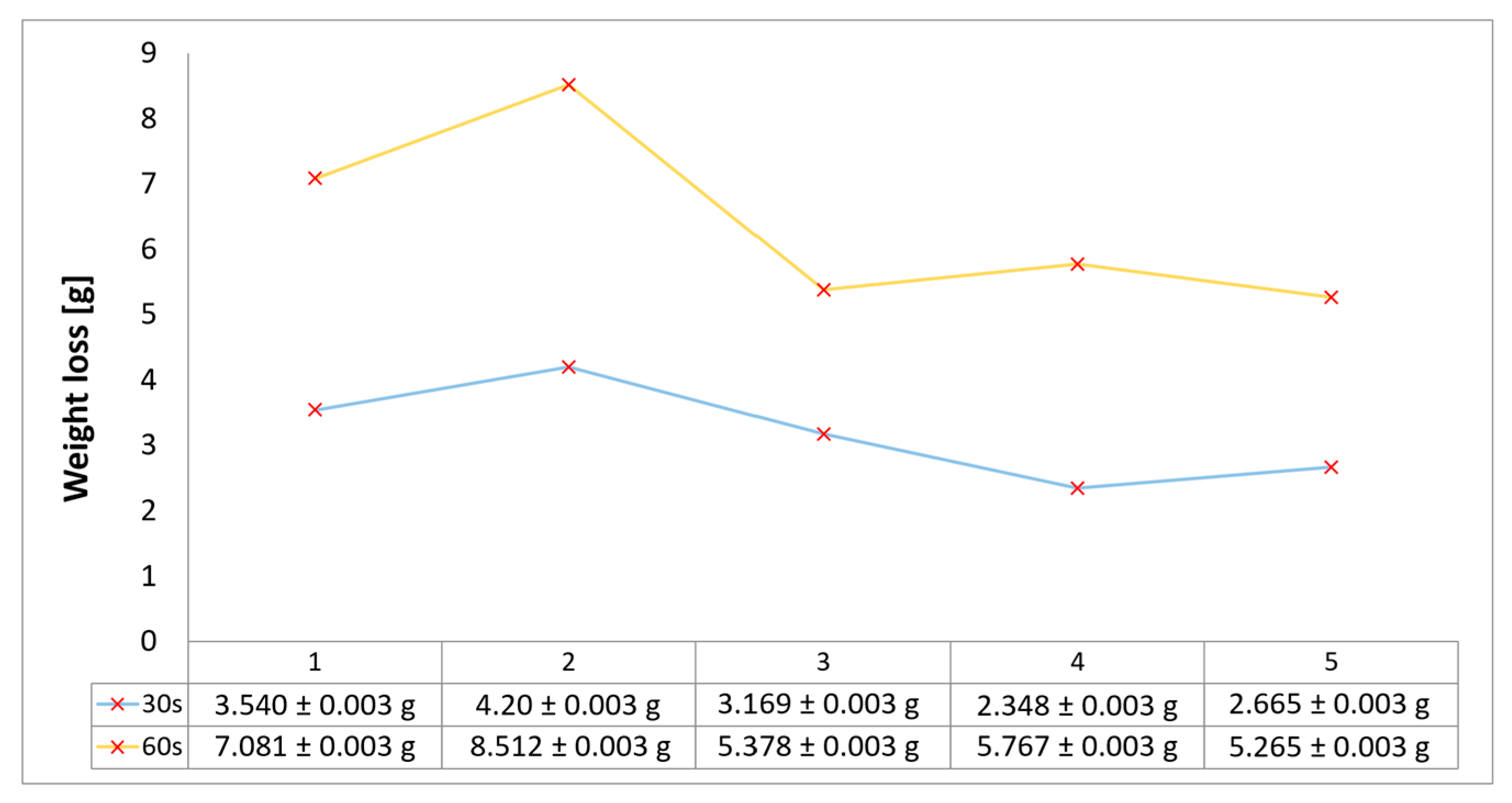
Figure 5 and follow roughly the same trends as the results for recession rates and thickness loss. The highest ablation mass loss was recorded for configuration 2, caused by the slot-filled material Al
2O
3 powder removal during the ablation test, followed by configuration 1, due to the partial removal of the Al
2O
3 surface coating layer during ablation. Configurations 1 and 3 exhibit an both a round 8% weight loss after 30 s of exposure, whereas by increasing the time exposure to 60 s, the weight loss was higher for configuration 1 due to the Al
2O
3 surface coating layer (with a higher density compared to the CFRP composite laminate disk of configuration 3), both eliminated during ablation tests. The best performing weight loss values match up to those for minimal thickness loss for configurations integrating the new air chamber thermal management concept with continuous fiber reinforcement of its frontal wall. Therefore, configuration 5 presented the lower weight loss values for both exposure times, very close to results obtained for carbon continuously reinforced configuration 4, both in the range of 5% (30 s exposure) to 10–12% (60 s exposure). Overall, the weight percentage losses for all tested samples vary from 5 to 10% after 30 s of flame time exposure and increase, varying between 10 and 22%, when increasing the time exposure to 60 s.
The synergetic effect of the new air chamber concept architecture providing low thermal conductivity by creating small airspaces within the material structure, along with the continuous front wall fiber reinforcement acting like a thermal barrier, emerged as a key outcome of the study and remains a central focus for future research optimization. A clear path of optimization of configurations 4 and 5 is to increase the continuous reinforcement phase volume fraction in both frontal and radial walls, potentially decrease the thickness of the frontal wall, and additionally investigate the possibility of reducing the number of air chamber structural architecture while improving the ablative resistance. A second route for future investigation is to continue the development of hybrid configurations like 3 by combining the benefits of CFRP thermoset composites with 3D-printed TPS structures and ultimately adding a surface coating protection.
3.4. Temperature and Time Analysis
Since temperature is the key parameter governing ablative degradation, recording the transient internal temperature profile is essential for understanding and characterizing the thermal response of the ablator-developed materials. Two embedded temperature probes (within the ablative material at two specified distances from the surface as shown in
Figure 1), each connected to a digital multimeter, continuously recorded the temperature of each sample from the start to the end of the test for both the 30 s and 60 s exposure durations.
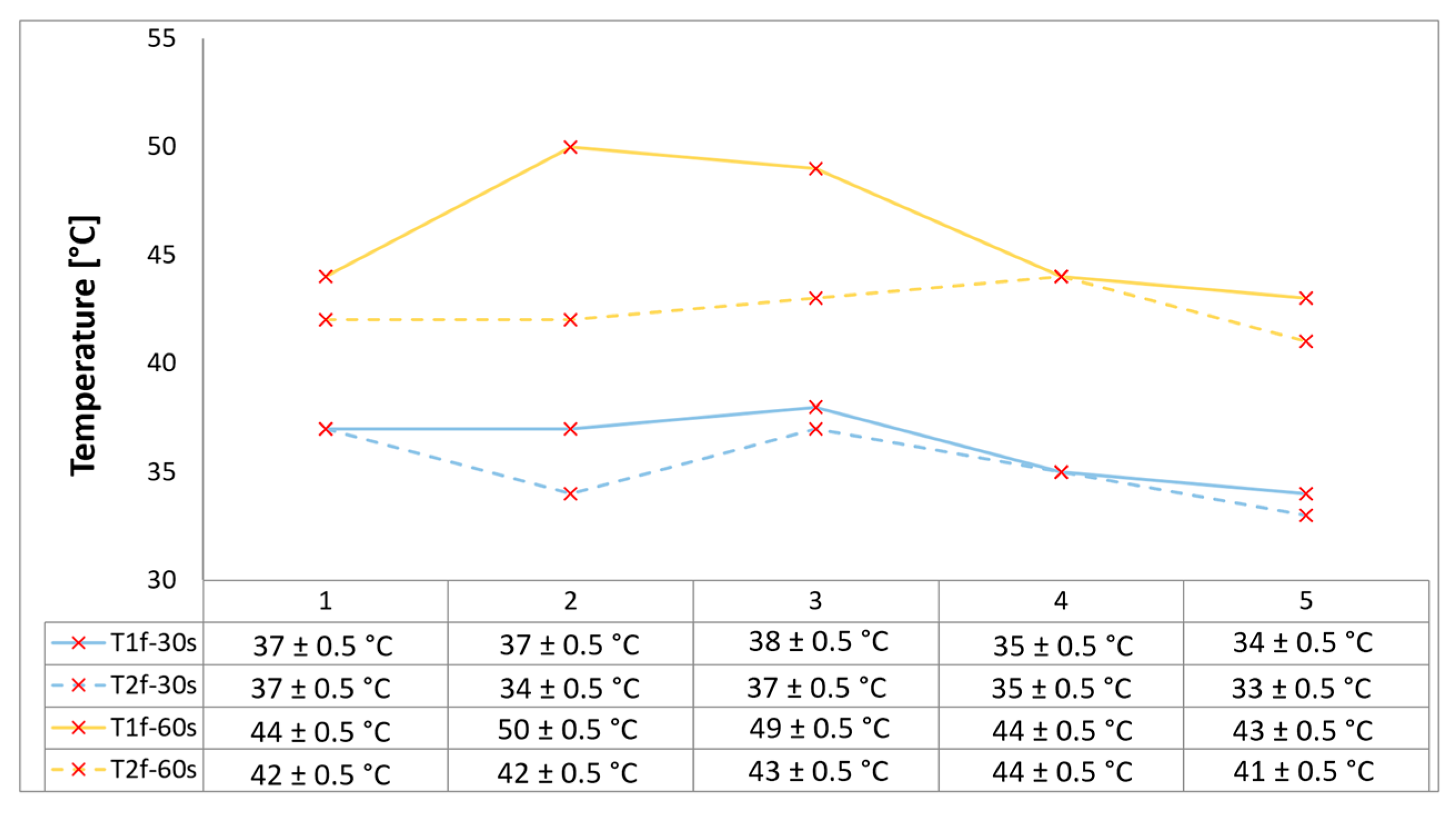
Figure 6 below provides the final recorded temperature values registered for each sample for both time exposures. In order to reduce latent distortion of the temperature measurements due to the difference in thermal diffusivity between the material and the measuring probe, the size and accuracy of ±0.75% were small, and the wires were installed perpendicular to the direction of the heat flow.
Configurations 4 and 5 exhibit a slightly lower temperature increase when compared with the other developed configurations, indicating an additional thermal protection barrier as a synergistic effect coming from the continuous fiber reinforcement (potentially heat was dissipated by re-radiation), beyond the low thermal conductivity novel internal thermal management architecture with three air chambers that has proven its benefits. Specifically, the continuously glass fiber reinforced configuration 5 exhibits the lower temperature increase due to its low thermal conductivity compared to carbon fibers.
A marginally higher temperature increase rate was recorded on 2 and 3 configurations, since both filling material slots were removed by the flame during tests, leaving the bulk material unprotected. Nevertheless, the novel three-air-chamber design provided effective thermal protection by minimizing thermal conductivity and convective heat transfer. The overall increase in temperature ranged from 5 to 10 °C for both measuring locations when increasing time exposure from 30 s to 60 s.
All samples exhibit excellent thermal insulation properties. Consequently, a general observation can be made regarding the temperatures measured at both locations (contact points situated on the rear walls of the second and third air chambers, as viewed from the front of the sample, as shown in
Figure 1), and that is none of the tested configurations caused the recorded temperature to rise above 50 °C, comfortably below the maximum allowable limit of 180 °C for the TPS back-face temperature, thus ensuring the spacecraft and its components remain within design integrity.
