Article

Analysis of the Applicability of Accelerated Conditioning Protocols in Concrete Beams Reinforced with Steel and GFRP: Effects of Chloride Exposure

by
Amanda Duarte Escobal Mazzú
and
Gláucia Maria Dalfré
*
Graduate Program in Civil Engineering (PPGECiv), Department of Civil Engineering (DECiv), Federal University of Sao Carlos (UFSCar), Sao Carlos 13565-905, Brazil
*
Author to whom correspondence should be addressed.
Polymers 2025, 17(17), 2423; https://doi.org/10.3390/polym17172423
Submission received: 30 July 2025 / Revised: 1 September 2025 / Accepted: 2 September 2025 / Published: 7 September 2025
(This article belongs to the Special Issue Sustainable Polymeric Materials in Building and Construction)

Abstract

The durability of Fiber-Reinforced Polymer (FRP) bars is typically evaluated using accelerated conditioning protocols (ACP), which are applied to bar samples, either directly exposed or embedded in small concrete specimens, under aggressive environmental conditions. Thus, this study investigates the applicability of the ACPs recommended by ACI440.9R (2015), from the American Concrete Institute, to assess the potential effects of chloride exposure on reinforced concrete beams. Twelve beams—six reinforced with steel and six with Glass Fiber-Reinforced Polymer (GFRP)—were tested under two scenarios: (1) a reference condition, with beams stored for 1000 h in a controlled laboratory environment, and (2) a conditioned condition, where beams were immersed in a 3.5% NaCl solution at 50 ± 3 °C for 1000 h prior to beam casting. After, the beams were evaluated through three-point bending tests, focusing on load–deflection behavior, failure modes, crack patterns, and strain distribution in concrete and reinforcement. The results indicated that chloride exposure adversely affected both steel and GFRP-reinforced beams. Steel-reinforced concrete beams exhibited a 12% reduction in load-bearing capacity due to steel corrosion, while the GFRP-reinforced concrete beams showed a 10% reduction in load-bearing capacity due to water absorption by the GFRP.

Graphical Abstract

1. Introduction

Traditional reinforced concrete structures may experience corrosion in steel reinforcement when exposed to aggressive environments, mainly due to carbonation or chloride attack. The primary cause of concrete structures deterioration is steel reinforcement corrosion, which leads to significant economic losses due to maintenance and the reduced performance of structural components [1,2,3,4,5,6,7,8]. Addressing the issue of steel reinforcement corrosion in aggressive environments is crucial for ensuring load capacity and durability of concrete structures [9]. As a result, alternative materials have been explored, with Fiber-Reinforced Polymers (FRP) emerging as a promising substitute for steel reinforcement in aggressive conditions [3,9,10,11,12,13]. Research and development in FRP composites have significantly increased over the past two decades. While this is not a new research area, there is still no consensus among researchers worldwide regarding the reliability and durability of FRPs [14].
FRP is a composite material that combines continuous fibers and a polymeric matrix (resin). The most used fibers are carbon, glass, aramid and basalt [6,15,16]. Among these fibers, glass emerges as a preferred choice for concrete reinforcement due to its chemical resistance, high strength-weight ratio, corrosion resistance, cost-effectiveness, and environmental sustainability [17,18,19,20,21]. The polymeric matrix is responsible for bonding the fibers and distributing the stresses imposed on the composite among individual fibers while protecting against abrasion, impact, and environmental conditions that could affect the durability of the FRP [22]. The resin used to produce the FRP is critical for achieving the desired mechanical properties and durability characteristics.
FRP is corrosion-resistant, exhibits high tensile strength, is lightweight, and transparent to electromagnetic fields [23,24,25,26,27,28]. Despite its advantages, FRP is susceptible to degradation in tensile properties when exposed to some aggressive conditions [29,30,31]. A significant reduction in the tensile strength of GFRP (Glass Fiber-Reinforced Polymer) bars can be observed due to polymer degradation, fiber-matrix debonding, or fiber corrosion [7,32]. In recent years, numerous studies have been conducted to investigate the durability of GFRP bars under various environmental conditions. The factors that contribute most to the degradation of GFRP are moisture absorption, alkaline environments, and temperature [3]. Moisture penetrates the polymeric matrix through solution flow in the micro gaps between polymer chains and via capillary transport across microcracks at the fiber/matrix interface or microcracks formed during manufacturing [33]. The polymeric matrix degrades through a hydrolytic reaction, in which water molecules interact with the ester groups in the polymer (such as polyester or vinyl ester resin), leading to irreversible chemical changes that reduce both toughness and fracture strain [27]. Consequently, the matrix undergoes plasticization, which induces reductions in strength and glass transition temperature [3]. One significant issue with using GFRP as reinforcement is its sensitivity to alkaline attacks due to the surrounding concrete and intrinsically aggressive environment. The alkalinity of the solution contained in concrete pores is primarily responsible for the degradation of GFRP bars [34]. This degradation occurs as hydroxyl ions (OH-) penetrate the polymeric matrix and react with resin ester, forming alcohol and carboxylic acid salt in a process known as hydrolysis [35]. As hydroxyl ions diffuse, silica bonds are broken, leading to a loss of weight and strength in the glass fibers [36].
Understanding the long-term degradation of GFRP materials under harsh environments is essential for achieving long-term durable performance over 75 years or more [37]. Since the use of FRP as reinforcement in concrete structures became widespread in the 1980s, and virtually all concrete structures with this type of reinforcement have been designed for a service life of over 40 years, most available data regarding their actual long-term performance is limited [26]. The durability of FRP is closely related to its long-term performance, which can be assessed over 20 to 50 years [38]. Most studies subjected GFRP bars to accelerated conditioning for 3 to 36 months at elevated temperatures [5]. One approach to identifying vulnerabilities in the long-term behavior of FRP involves applying accelerated conditioning protocols (ACPs), such as those outlined in ACI 440.9R [31]. Using these ACPs, combined with the characterization of the mechanical properties over time, allows for the assessment of material durability. Most studies have utilized accelerated conditioning techniques, where FRP bars are immersed in aggressive solutions at elevated temperatures to evaluate their physical and mechanical integrity over time [3,10,15,19,39,40]. However, ACPs are applied to FRP bar samples and not to concrete elements reinforced with FRP, disregarding the interaction between the concrete and the embedded FRP reinforcement. This approach tends to be more severe than the material degradation observed in service [3,19,32,41]. In real-world scenarios, the FRP bar will not be directly exposed to the aggressiveness of the environment. Chen et al. [32] investigated the durability of non-protected and concrete-protected GFRP bars, manufactured with E-glass fibers and vinyl ester resin, under accelerated aging environments. After 2 months of exposure to an environment simulating the pore solution of concrete at 60 °C, the tensile strength retention of the GFRP bars was 52%. For the concrete-protected GFRP bars, the tensile strength retention was 61% after 3 months of exposure. The authors concluded that simulated environments were more aggressive to non-protected GFRP bars than those embedded in concrete. Therefore, evaluating the behavior of bars embedded in concrete provides a more realistic expectation of the degradation that bars may undergo when used as reinforcement in concrete structures [15].
According to Bulletin 40 [29], from the International Federation for Structural Concrete (fib), distinguishing between degradation caused by chloride attack, moisture diffusion, and alkalinity remains challenging. GFRP bars exposed to the combined effects of chlorides and moisture in concrete have demonstrated reductions in strength and stiffness by approximately 50%. The deterioration of FRP materials may not solely be attributable to chloride attack, but also to alkaline attack or matrix plasticization induced by moisture action. Robert, Cousin, and Benmokrane [42] conducted accelerated tests to assess the durability of GFRP bars, manufactured with E-glass and vinyl ester resin, when embedded in concrete. After 8 months of exposure to tap water at 50 °C, the tensile strength retention of the samples was 85%. In another study, Robert and Benmokrane [43] subjected GFRP bars (E-glass and vinyl ester resin) embedded in concrete to a 3% saline solution (NaCl) at 23 °C, 40 °C, and 50 °C for 60, 120, 210, and 365 days. After 365 days of exposure to the saline solution at 50 °C, the tensile strength retention was 89%. Additionally, GFRP bars embedded in concrete were exposed to a 3 % saline solution (NaCl) and tap water at 70 °C for 120 days. The results did not reveal significant differences in the durability of GFRP bars immersed in either tap water or saline solution, thereby confirming the long-term durability of GFRP bars under saline solution exposure. The authors predicted that, even after a service life of 100 years, the tensile strength retention of the studied bars would remain at 70% and 77% for average annual temperatures of 50 °C (average annual temperature in the Middle East and other hot regions) and 10 °C (average temperature of northern regions), respectively. Almusallam et al. [44] investigated the effects of different environmental conditions on the properties of GFRP bars (E-glass and vinyl ester resin) embedded in concrete over 6, 12, and 18 months. The residual tensile strength testing results showed that the specimens conditioned in tap water at 50 °C experienced more pronounced degradation than those exposed to seawater at the same temperature. The tensile strength ranged from 83% to 76% for exposure to tap water, and between 86 % and 84% for exposure to seawater. Fergani et al. [2] examined the degradation of GFRP bars (ECR glass and vinyl ester resin) embedded in concrete and conditioned in tap water at 60 °C for up to 9 months, observing tensile strength retentions between 80% and 59%. Jia et al. [4] analyzed the short-term durability of GFRP bars, manufactured with E-glass and vinyl ester resin, embedded in concrete and exposed to various solutions and ambient humidity. The results indicated that the specimens subjected to tap water and saline solution for 4 months exhibited tensile strength retentions of 61.6% and 60.7%, respectively. Morales et al. [26] investigated the durability performance of ECR glass and vinyl ester manufactured GFRP bars embedded in concrete mixed with seawater. The GFRP bars embedded in concrete were exposed to conditions simulating typical field environments in a subtropical region and seawater at 60 °C for 1, 6, 12, and 24 months. After mechanical and physical evaluations, these researchers concluded that environmental conditions influenced the tensile strength of the GFRP bars. Based on an experimental degradation model, the long-term prediction of the tensile strength retention averaged 92% under subtropical region exposure and 72% under seawater at 60 °C. Li et al. [45] investigated the durability of GFRP bars manufactured with vinyl ester resin exposed to seawater, alkaline-saline solution, and seawater immersion within the concrete, all maintained at 60 °C. After Scanning Electron Microscopy (SEM) analysis, the researchers reported no visible damage to the bars after 183 days of exposure to seawater at 60 °C. However, GFRP bars exposed to the alkaline-saline solution and immersed in concrete, as well as those exposed to seawater exhibited varying degrees of fiber-matrix separation after 183 days. This phenomenon was attributed to matrix swelling caused by water absorption. Openings in the polymeric matrix of samples exposed to the alkaline-saline solution were observed, which were attributed to the erosion effect of hydroxyl ions. Pits were also observed in samples immersed in concrete and exposed to seawater, attributed to the hydrolysis reaction. Wang et al. [46] subjected GFRP bars (vinyl ester resin) embedded in concrete mixed with seawater and sea sand to wet-dry cycles in chloride solution for 90, 180, and 270 days. These cycles involved immersion in a 3.5% NaCl solution at a temperature of 40 ± 2 °C for 12 h, followed by drying in an environment with a temperature of 25.2 ± 8.9 °C and humidity of 65.3 ± 16.6% for another 12 h. After the exposure, the bars underwent axial tensile tests, and tensile strength retentions of 81%, 76%, and 76% were observed after 90, 180, and 270 days of exposure, respectively. The researchers note that the degradation of the tensile strength slowed after 90 days of exposure. This reduction in the rate of degradation is attributed to the accumulation of Friedel’s salt, which forms from reactions between chloride ions and tricalcium aluminate in the cement, hindering the penetration of the solution into the GFRP bars, delaying the effects of polymer matrix hydrolysis and GFRP bar degradation. Table 1 provides tensile strength retention results of GFRP bars in concrete.
Previous durability investigations of GFRP reinforcement have primarily applied ACPs at bar level (Table 2), evaluating residual tensile capacity, elastic modulus, or interlaminar shear strength.
This study uniquely contributes to durability research by extending ACI 440.9R [31] accelerated conditioning protocols to the structural scale. Unlike prior work that has been limited to isolated bars, our investigation applies chloride exposure protocols directly to reinforced-concrete beams, providing a benchmark that bridges material-level degradation and structural performance. This approach enables (i) verification of whether ACPs remain sufficiently severe at the full-scale beam, (ii) direct comparison of steel and GFRP reinforcement under identical chloride attack, and (iii) assessment of the conservatism of ACI 440.1R [30] provisions after accelerated degradation.

2. Experimental

Twelve reinforced concrete beams were designed according to ACI 318 [47] and ACI 440.1R [30], utilizing steel and GFRP bars for the longitudinal reinforcement, respectively. Six beams were reinforced with 10 mm diameter steel bars, while the remaining six featured 10 mm diameter GFRP bars. Since steel reinforcement corrosion is a primary cause of deterioration in reinforced concrete structures, and corrosion resistance is a key characteristic of FRP, a chloride solution was employed for the accelerated conditioning protocol of the beams. Within each set of six beams, two were stored in a controlled laboratory environment for 45 days (reference), two were exposed to a laboratory environment for 1000 h, and two were immersed in a 3.5% NaCl solution tank with a temperature of 50 ± 3 °C for 1000 h, as detailed in Table 1. The duration of 1000 h of immersion in 3.5% NaCl at 50 ± 3 °C was adopted in accordance with the ACI 440.9R [31] guidelines for accelerated conditioning protocols of FRP reinforcement. This exposure length has been widely used in bar-level studies (e.g., Fergani et al. [2]; Benmokrane et al. [22]; Robert et al. [42]; Robert and Benmokrane [43]) as a standardized baseline to evaluate comparative durability, rather than as a direct simulation of a field service period. In this work, the same protocol was applied at the full-scale beam with the objective of (i) maintaining comparability with existing durability data at the material level, and (ii) ensures comparability with the extensive database of bar-level degradation, while providing insight into whether the severity of ACPs is sufficient to induce measurable differences at the structural scale. So, the study therefore provides a structural-level benchmark that can complement service-life modeling or field-exposure studies in future research.
It is important to note that the 1000 h periods were initiated 45 days after concrete casting, following the testing of the reference beams. As indicated in Table 3, concrete, steel, and GFRP specimens were subjected to the same exposure environments as the beams and tested to determine their mechanical properties.
The beams were designated as Vx_y_z_w, where x is equal to 1 or 2 based on the model repetition, y is equal to LAB for laboratory exposure environment or ACP for accelerated conditioning protocol, z is equal to S for steel reinforcement or GFRP for GFRP reinforcement, and w is equal to 45 days or 1000 h, corresponding to the age of the beams at the time of testing. For instance, V1_ACP_GFRP_1000h represents the first beam reinforced with GFRP tested after 1000 h of exposure to chloride attack. It is important to acknowledge that only two replicas were tested, which is below the minimum generally recommended for more rigorous statistical treatment. This decision was motivated by the consistent behavior typically observed among specimens reinforced or strengthened with FRP systems, as well as by the fact that full-scale structural tests are both costly and time-consuming. Therefore, the results should be interpreted as preliminary trends rather than statistically generalizable outcomes.

2.1. Material Properties

Concrete cylinders with a diameter of 100 mm and a height of 200 mm underwent compressive strength and elasticity modulus testing, following the Brazilian Standards ABNT NBR 5739 [48] and ABNT NBR 8522 [49], respectively. Three specimens were used to determine the compressive strength, and two were used for elasticity modulus at each age. The target concrete compressive strength was 30 MPa.
For each age and exposure environment, two steel bars with a length of 60 cm and a diameter of 10 mm underwent tensile tests, according to ABNT NBR ISO 6892-1 [50], to obtain the stress–strain behavior and elasticity modulus. The steel’s nominal yield strength and elasticity modulus were 500 MPa and 200 GPa, respectively.
Concerning the manufacturer, the GFRP bars used in the experimental program were produced with glass fibers resistant to alkaline environments and epoxy ester-vinyl resin, with a surface conformation characterized by helical grooves, as depicted in Figure 1, and presents tensile strength and an elasticity modulus of 1047 MPa and 48 GPa, respectively. According to NBR 17201-1 [51], GFRP or BFRP (Basalt Fiber-Reinforced Polymer) bars must meet the minimum mechanical properties presented in Table 4, among others. Additionally, the bars must be between the area limits of the cross-section to define the nominal diameter, as shown in Table 5.
The determination of effective diameter and effective area of the GFRP bars were performed in accordance with NBR 17201-2 [52]. Tensile tests were conducted on five specimens of GFRP bars with a length of 100 cm and a diameter of 10 mm for each exposure environment, following the ABNT NBR 17201-3 [53] procedures, to determine the stress–strain behavior and elasticity modulus. In consideration of the samples remaining protected, without contact with water or exposure to weather conditions, tensile tests were conducted on the reference specimens, and the results were extrapolated to the specimens maintained for 1000 h in the laboratory environment. The tensile tests of GFRP bars required steel anchors at each end of the specimen due to the low compressive strength of GFRP compared to its tensile strength, preventing GFRP crushing by the machine clamps. The steel anchors provide uniform pressure on the GFRP bars and avoid slippage as the tensile load increases [53]. Thus, Schedule 40 steel tubes with a length of 30 cm were used at each end, and the free length of the GFRP bar was 40 cm, as shown in Figure 2. The Sikadur 32 epoxy adhesive was used to bond the GFRP bar to the steel tube, and the alignment between GFRP bars and the steel tube was ensured using circular spacers made by 3D printing.
The fiber content was determined by combustion method according to ABNT NBR 17201-10 [54]. Figure 3 presents the materials characterization tests. All tests were conducted on an EMIC DL-60000 universal testing machine with a capacity of 600 kN, using a 150 mm electronic extensometer.

2.2. Reinforced Concrete Beams

The twelve reinforced concrete beams had a cross-sectional dimension of 12 × 20 cm, an overall length of 250 cm, and a free span of 230 cm. The positive longitudinal reinforcement of the beams consisted of two steel or GFRP bars with a 10 mm diameter (longitudinal reinforcement rate of 0.75%). The negative longitudinal reinforcement was composed of two steel bars with a 6.3 mm diameter (to ensure the positioning of the stirrups), and the stirrups consisted of steel stirrups with a 5 mm diameter and a spacing of 10 cm, as shown in Figure 4. A concrete cover of 1.5 cm was used, smaller than that prescribed by most design codes for durability considerations. As such, chloride ingress was likely accelerated, amplifying the observed effects of exposure. This limitation means the results should be interpreted as a relative comparison between reinforcement types under severe accelerated conditions, rather than as direct field predictions for typical cover depths. The stirrups of the beams maintained under chloride attack were protected from corrosion using zinc-rich epoxy paint.
The steel and GFRP reinforced concrete beams were designed according to ACI 318 [47] and ACI 440.1R [30], respectively, to predict the nominal moment capacity and failure mode using the experimental data from the material testing results. Table 6 presents the nominal moment capacity (Mn), the maximum resisted force (Fmax), and the expected failure mode for the beams.
According to Table 6, the design failure mode was a concrete crushing or balanced rupture, where the bar rupture and concrete crushing occur simultaneously. Concrete crushing is a brittle failure mode, but, as GFRP bars do not exhibit yielding like steel reinforcement, it is more desirable than GFRP rupture for this type of structure because there is still some ductility due to the development of the plastic behavior of concrete. If GFRP reinforcement fails, it can be catastrophic and occur without warning [6,16,30,55].

2.3. Exposure Environments

After testing the reference specimens, the remaining beams, concrete, steel, and GFRP specimens were exposed to two different environments: (a) a laboratory environment (internal and protected) and (b) a conditioning tank containing a NaCl solution with a concentration of 3.5% and a temperature of 50 ± 3 °C, following ACI 440.9R [31] adapted for the use of NaCl solution. These specimens remained in exposure environments for 1000 h.
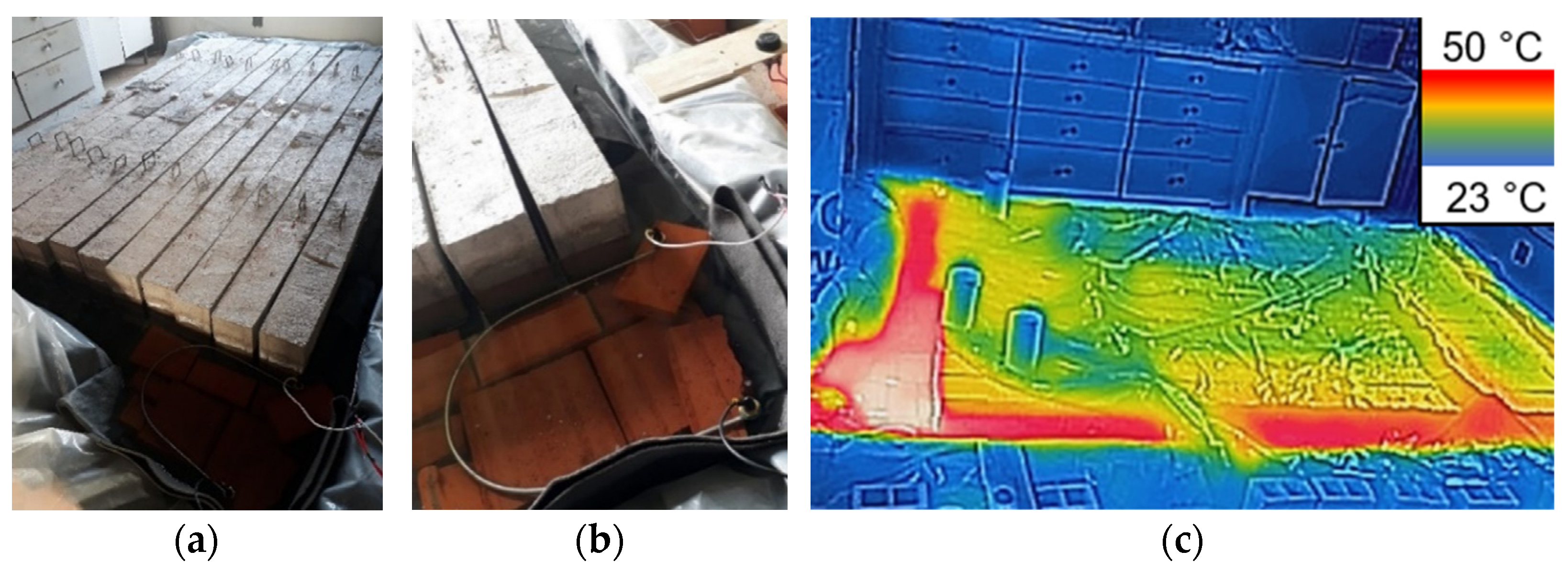
The conditioning tank was constructed in a protected environment using juxtaposed ceramic blocks, as shown in Figure 5a. The beams, concrete, steel, and GFRP specimens were positioned on ceramic blocks, allowing complete involvement, and the conditioning tank was filled with NaCl solution. The beams were immersed to a depth of 8 cm, and the conditioning tank was covered with a plastic cover.
For solution heating, a system consisting of an immersed resistance of 2000 W connected to a 30 A thermostat was used (Figure 5b). The solution temperature was periodically checked using a digital thermometer and thermographic images obtained with a FLIR Lepton camera, as shown in Figure 5c.

2.4. Instrumentation and Test Setup

Three-point bending tests were conducted to evaluate the flexural behavior of reinforced concrete beams after environmental exposure. The main parameters investigated included the load-deflection behavior, failure modes, crack pattern, and strains in concrete and longitudinal reinforcement.
The instrumentation of reinforced concrete beams involved using linear variable differential transformers (LVDT) and strain gauges (SG). Following the design of the reinforcements, the center of one steel and GFRP bar of the positive longitudinal reinforcement of each beam was prepared and strain gauges of 120 Ω and a reading grid length of 10 mm were attached to measure the strain along the test (Figure 6a,b). Strain gauges with a resistance of 120 Ω and a reading grid length of 50 mm were also bonded to the concrete surface to measure the concrete compressive strain (Figure 6c).
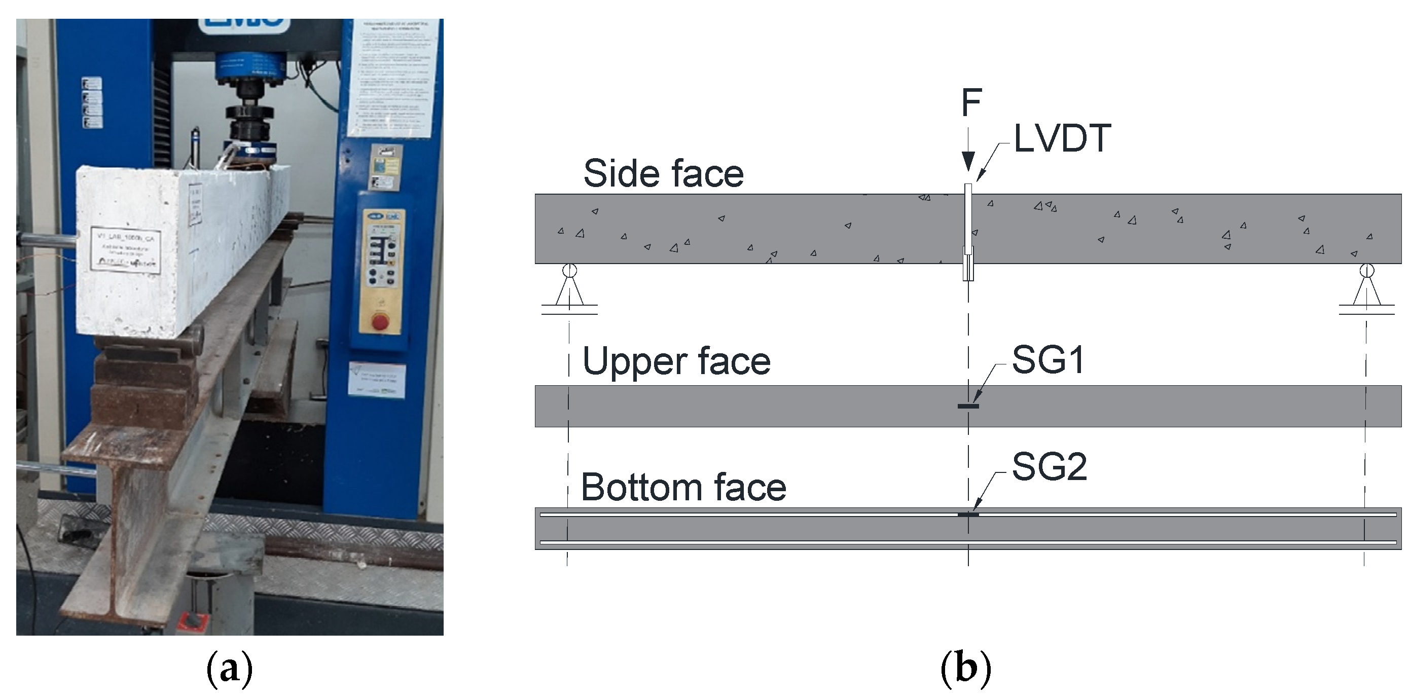
The three-point bending tests were conducted using an EMIC DL-60000 universal test machine with a maximum capacity load cell of 600 kN and read resolution of 0.1 kN. Displacement control was achieved through the internal transducer of the test machine with a rate of 1 mm/min, while the applied load was measured by the load cell (Figure 7).
The vertical displacement at the mid-span was measured using a Vishay LVDT with a reading field of 100 mm (±0.01 mm) fixed to an external support. Figure 8a presents the execution of the three-point bending test, and Figure 8b illustrates the instrumentation utilized, with SG1 and SG2 representing the strain gauges responsible for measuring concrete and steel/GFRP longitudinal reinforcement strains, respectively.
All test data was recorded in a data acquisition system.

2.5. Chloride Penetration Depth

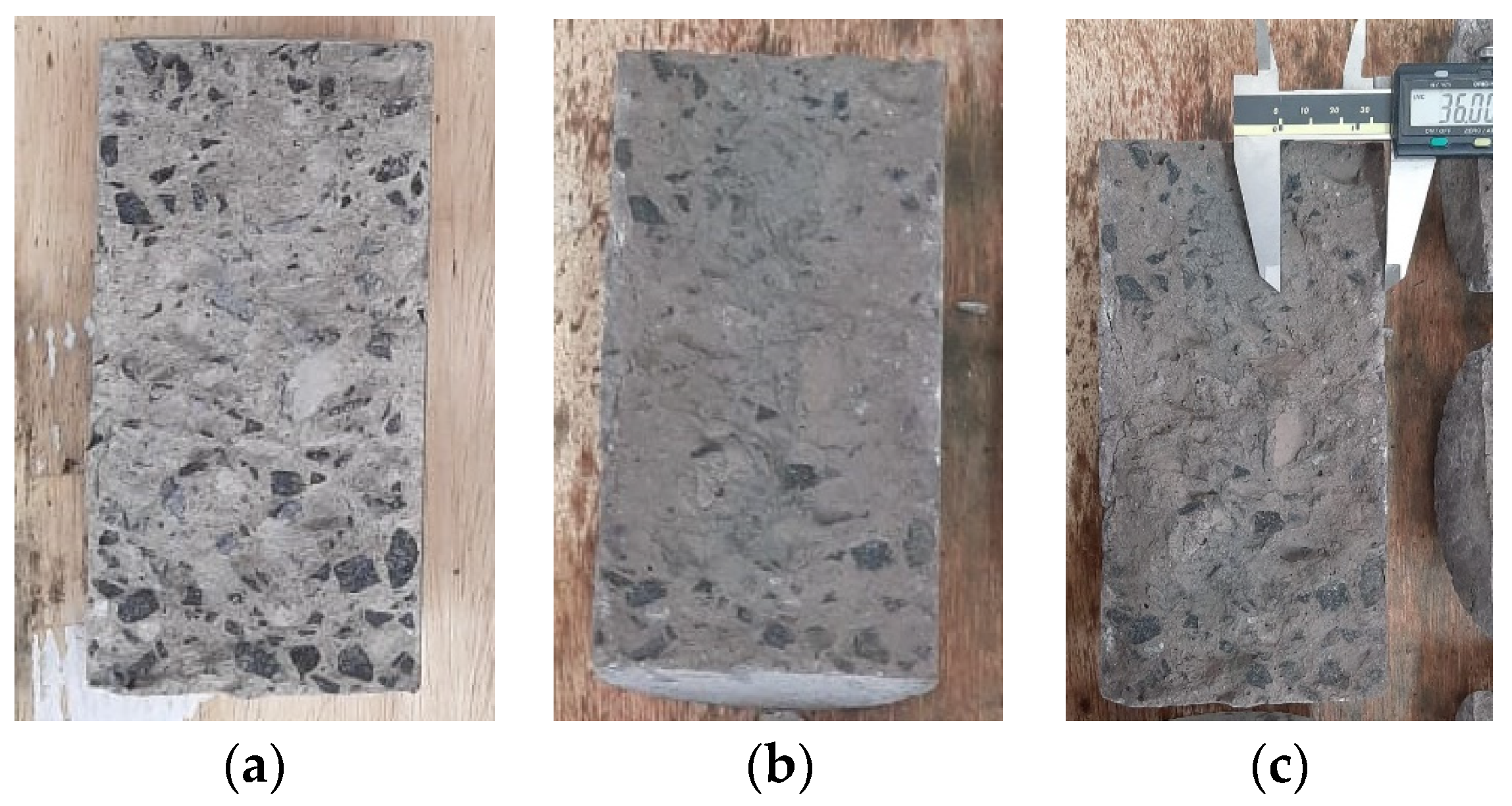
The chloride penetration depth was assessed using the colorimetric method, which involves applying silver nitrate to the concrete surface to evaluate the extent of chloride attack. In the absence of chlorides, the concrete darkens, whereas in the presence of chlorides, the color remains clear, as shown in Figure 9. This figure illustrates a freshly fractured concrete surface (a) and a fractured surface to which silver nitrate has been applied (b). The central region of the concrete surface appears darker, indicating the area unaffected by chlorides. This test was performed to determine the chloride penetration depth in three concrete specimens exposed to a conditioning tank for 1000 h.

3. Results

3.1. Concrete, Steel, and GFRP

Table 7 presents the results obtained in materials characterization, where fcm and Ecm correspond to the compressive strength and elasticity modulus of concrete, fy, esy, and Es correspond to the yield strength, yield strain, and elasticity modulus of steel, respectively, and ffu, efu, and Ef correspond to the tensile strength, rupture strain, and elasticity modulus of GFRP. The coefficients of variation reported in Table 7 ranged from 1 to 10%. Thus, the relatively low COVs confirm the reliability of the experimental results and reduce concerns regarding variability from specimen preparation or testing.
Figure 10 depicts the failure mode of GFRP bars subjected to tensile test. It occurred along the free length of the specimen and was attributed to the rupture of glass fibers, where splitting was observed.
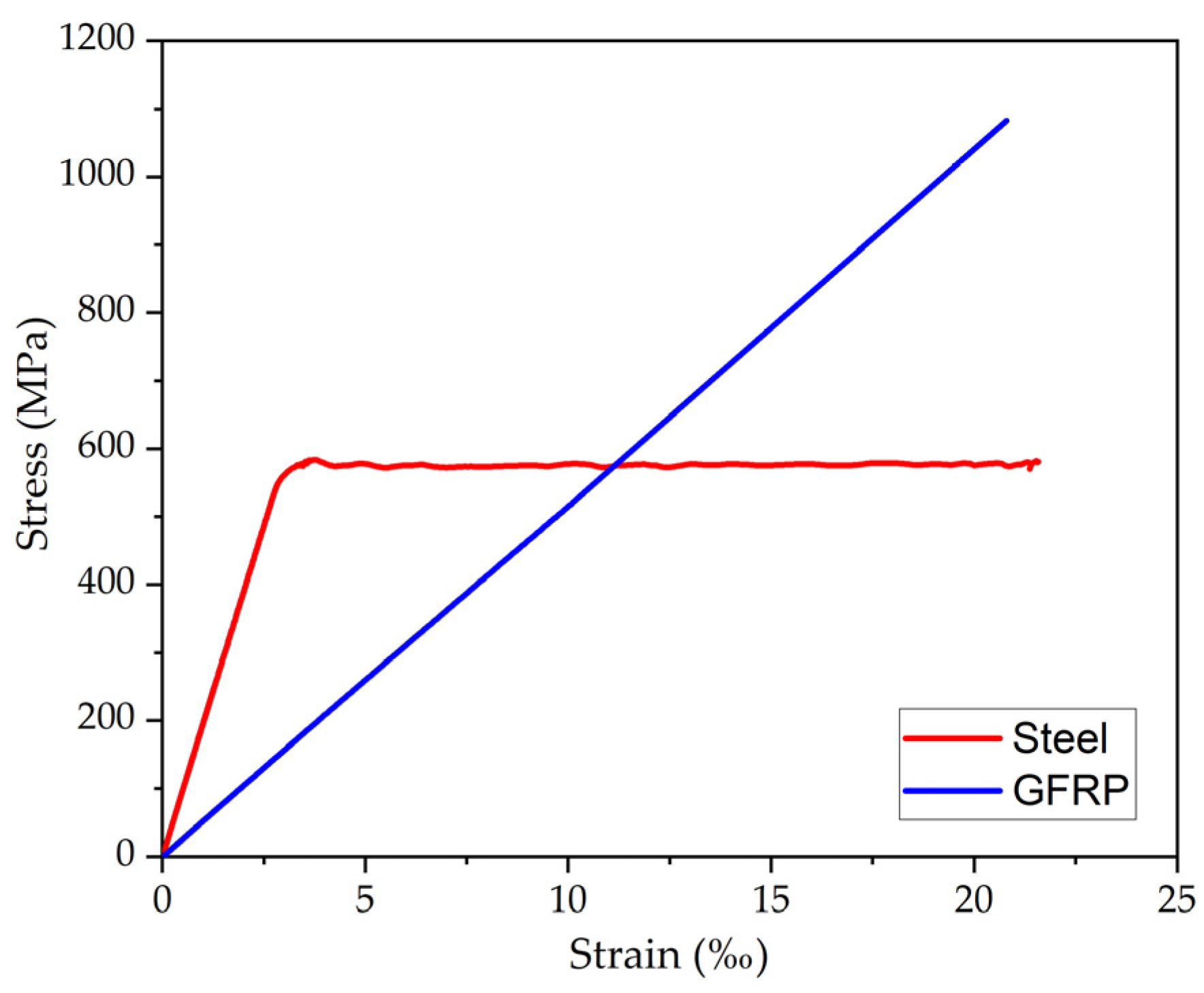
Figure 11 presents the average stress–strain curves of reference steel and GFRP bars. While steel bars exhibit a clear yielding condition, indicative of ductile behavior, GFRP bars demonstrate linear behavior until failure, with a brittle rupture. The difference in the slopes of the curves highlights the disparity in the modulus of elasticity between the materials, considering that the modulus of elasticity of steel is approximately four times higher than that of GFRP. Additionally, it is observed that the tensile strength in GFRP is approximately two times higher than that of steel.
Concerning the GFRP bar diameter, an average effective diameter of 9.44 mm, leading to an average effective area of 69.98 mm2, was obtained. Comparing the average effective area obtained with the limits presented in ABNT NBR 17201-1 [51] (available in Table 5), it is noted that this value falls within the range of 47.2 to 70.7 mm2. Therefore, the nominal diameter of the GFRP bars used as reinforcement in the concrete beams is 8 mm.
Finally, for the fiber content, an average value of 77.2% was obtained, higher than 75% specified by ABNT NBR 17201-1 [51].

3.2. Chloride Ions Penetration Depth

The chloride penetration depth test was conducted on concrete specimens subjected to a conditioning tank for 1000 h. For this purpose, three concrete specimens were fractured by diametrical compression tensile, and a silver nitrate solution was sprayed on the concrete surface. The chloride penetration depth was then quantified using a digital pachymeter, as depicted in Figure 12. The obtained depth values were 34.89 mm, 36.42 mm, and 36.91 mm for each specimen. These values significantly exceed the concrete cover thickness of 15 mm, providing clear evidence that chlorides reached the longitudinal reinforcements.

3.3. Reinforced Concrete Beams

Table 8 provides a summary of the results obtained for each beam, where F denotes the recorded applied load (kN), δ represents the vertical mid-span displacement (mm), εs/f is the reinforcement strain (‰), and εc denotes the concrete strain (‰). These results were assessed at the cracking initiation, yielding of steel reinforcement, concrete crushing, and when the maximum load was obtained.
A specific stop criterion was not established during the testing of reference concrete beams reinforced with steel bars (V_LAB_S_45d). Subsequent tests on reference concrete beams reinforced with GFRP bars (V_LAB_GFRP_45d) were conducted until the longitudinal reinforcement rupture revealed displacements of approximately 70 mm. Consequently, for the remaining steel-reinforced beams (V_LAB_S_1000h and V_ACP_S_1000h), the test stopped when the beams reached a displacement of 75 mm. In the case of the remaining GFRP-reinforced concrete beams (V_LAB_GFRP_1000h and V_ACP_GFRP_1000h), the stop criterion remained the rupture of longitudinal reinforcement. It was noted that some strain gauges suffered damage due to the presence of water (V2_LAB_S_1000h, V1_ACP_GFRP_1000h, and V2_ACP_GFRP_1000h) or due to the development of concrete cracks in the positive region.
It can be observed in Table 8 that, at the onset of yielding in the steel reinforcement, tensile strains in the longitudinal reinforcement ranged between 2.1‰ and 2.4‰, while compressive strains in the concrete were approximately 1.0‰. Concerning the initiation of concrete crushing, concrete strains of around 3.0‰ were recorded, similar to the concrete crushing value indicated on ACI 318 [47] and ACI 440.1R [30].
Figure 13a presents the average Load vs. displacement relationship of the beams, and Figure 13b,c present the average Load vs. strains in concrete and longitudinal reinforcements.
Figure 13a analysis reveals a typical behavior of concrete beams reinforced with steel bars, delineated by three stages. The initial stage represents uncracked concrete, exhibiting linear elastic behavior. The second stage depicts cracked concrete with steel in the elastic regime, followed by a reduction in the element stiffness. The final stage includes the cracked concrete with steel yielding, presenting a well-defined yield level. In contrast, concrete beams reinforced with GFRP bars exhibit behavior characterized by two stages. The first stage corresponds to uncracked concrete, showing a linear elastic behavior. The second stage illustrates cracked concrete and GFRP with an approximately linear behavior until rupture.
In the pre-cracking phase, all beams exhibited similar behavior characterized by high bending stiffness, as the concrete works in the elastic regime, effectively resisting the applied loads. However, post-cracking, there was a transition where the reinforcement started to resist the applied loads. This transition was evident in the altered inclination of the curves, showing a loss of bending stiffness in the structural elements. The reduction in bending stiffness from pre- to post-cracking was approximately 49%, 59%, and 60% for beams V_LAB_S_45d, V_LAB_S_1000h, and V_ACP_S_1000h, respectively. Notably, concrete beams reinforced with GFRP bars exhibited a more significant decrease in bending stiffness of approximately 76% due to the lower elasticity modulus of GFRP. Specifically, the reduction in bending stiffness from pre- to post-cracking was approximately 91%, 86%, and 81% for beams V_LAB_GFRP_45d, V_LAB_GFRP_1000h, and V_ACP_GFRP_1000h, respectively. Comparatively, the bending stiffness of V_LAB_GFRP_45d, V_LAB_GFRP_1000h, and V_ACP_GFRP_1000h was 66%, 72%, and 70% lower than that of V_LAB_S_45d, V_LAB_S_1000h, and V_ACP_S_1000h, respectively. These results underscore the substantial impact of GFRP reinforcement on the post-cracking bending stiffness of concrete beams, owing to the inherent characteristics of GFRP bars, such as their lower elasticity modulus.
The lower elasticity modulus of GFRP bars also impacted the displacements observed in GFRP-reinforced concrete beams, resulting in higher vertical displacements than steel-reinforced concrete beams. Concerning concrete crushing, the vertical displacements of the GFRP-reinforced concrete beams were approximately 78% greater than those of steel-reinforced concrete beams. Despite the larger displacements, GFRP-reinforced concrete beams exhibited superior loading-carrying capacity than steel-reinforced concrete beams. The maximum attained applied loads of the V_LAB_GFRP_45d, V_LAB_GFRP_1000h, and V_ACP_GRFRP_1000h beams were 37%, 27%, and 28% higher than those of the V_LAB_S_45d, V_LAB_S_1000h, and V_ACP_S_1000h beams, respectively. This difference can be attributed to the high tensile strength of GFRP bars.
In the context of exposure environments, the V_ACP_S_1000h beams exhibited maximum loading-carrying capacity 12% lower than the V_LAB_S_1000h beams while exhibiting no disparity in stiffness. This discrepancy is due to the degradation of steel reinforcement induced by corrosion. The V_ACP_GFRP_1000h and V_LAB_GFRP_1000h beams demonstrated comparable stiffness, yet the former experienced fracture with force and displacement values approximately 10% and 8% lower than the V_LAB_GFRP_1000h beams. This discrepancy can be attributed to the water absorption by GFRP bars.
The beam-level performance observed in this study aligns well with existing durability benchmarks for GFRP reinforcement. Robert, Cousin and Benmokrane [42] and Robert and Benmokrane [43] demonstrated that chloride and moist concrete exposures reduce bar strength and bond, effects that were reflected at the structural scale in the ≈10% reduction in GFRP-RC beam capacity. Similarly, Benmokrane et al. [22] reported strength retention between 85 and 95% for epoxy-based GFRP bars after 1000 h saline/alkaline conditioning; the ≈90% capacity retention observed in present beams is quantitatively consistent with this range.
Figure 13b,c illustrate the distinctions in the applied load-strain curves of concrete and longitudinal reinforcement, presenting analogous stages found in the applied load–displacement curves of reinforced concrete beams. In the post-cracking elastic stage, for the same load level, the concrete in beams reinforced with GFRP bars exhibits deformations approximately twice as large (Figure 13b). For the steel-reinforced beams, a plateau is observed, whereas the GFRP-reinforced beams show an approximately linear response, with deviation from linearity occurring beyond strains of about 2‰, corresponding to the onset of the plastic behavior of concrete. With respect to Figure 13c, a plateau can be observed in the load–strain curves of the steel-reinforced beams, while the GFRP-reinforced beams display a linear behavior up to failure, similar to that observed in tensile tests. In the post-cracking elastic stage, deformations about three times larger are observed.
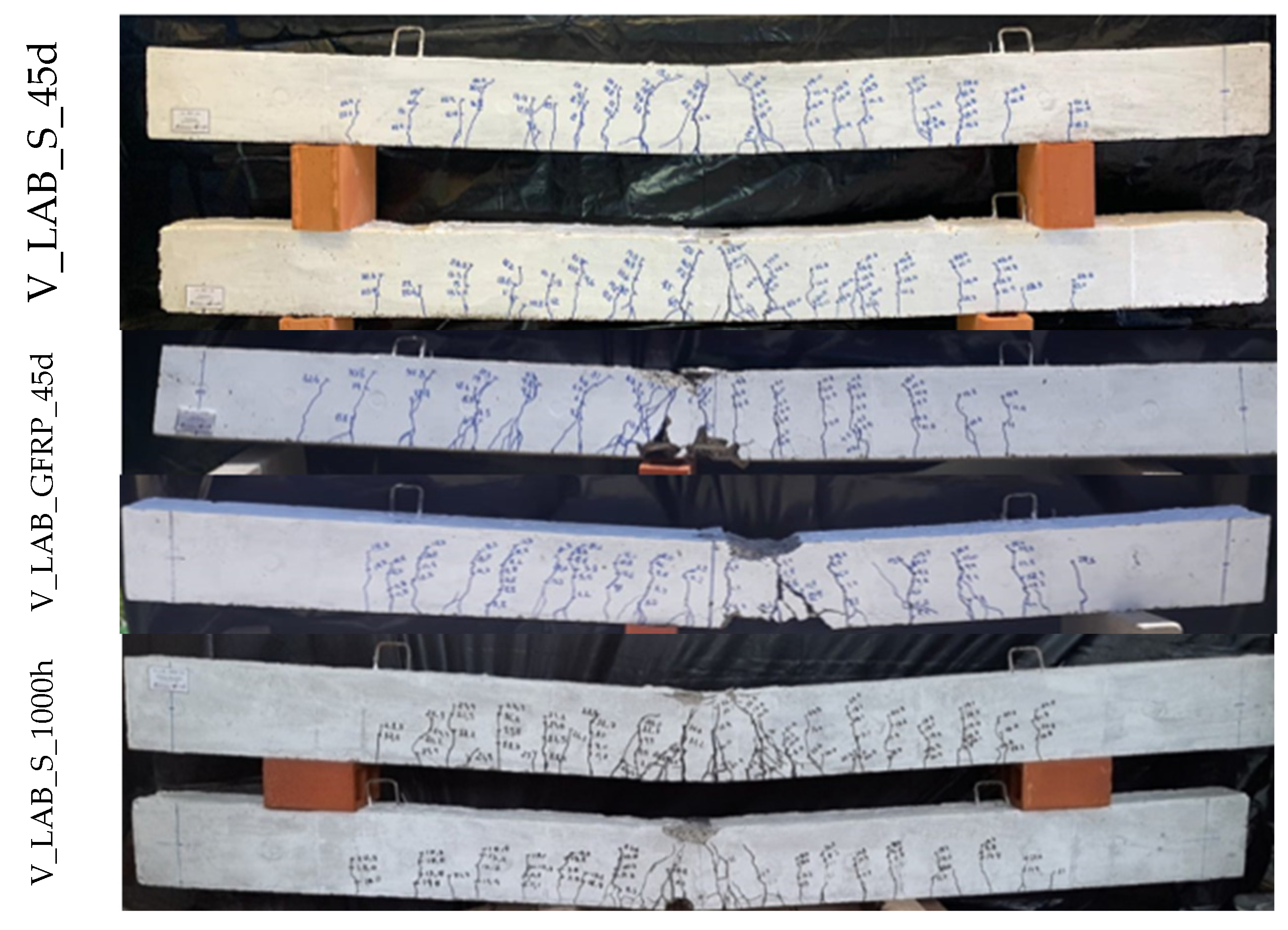
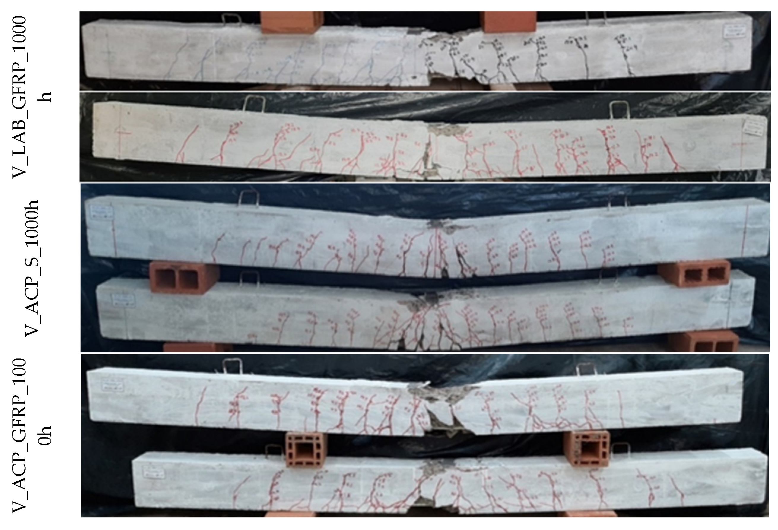
The failure mode observed in steel-reinforced concrete beams was ductile and characterized by steel yielding followed by concrete crushing. In contrast, GFRP-reinforced concrete beams exhibited a failure mode involving concrete crushing followed by GFRP rupture, representing a brittle failure mode. Figure 14 presents the failure mode of the beams and Figure 15 illustrates the crack pattern of the beams.
Initially, the cracks exhibited a vertical orientation at the mid-span of the beams due to bending. As the applied load increased, the cracks assumed an inclined trajectory while propagating towards the supports, owing to the combined influence of bending and shear. These cracks extended vertically along the height of the beams, progressing towards the compression zone. Due to the low modulus of elasticity of GFRP bars, concrete beams with GFRP bars experienced higher deflections and larger crack widths when compared to concrete beams reinforced with steel bars [16,56]. Beams V_LAB_GFRP_45d, V_LAB_GFRP_1000h, and V_ACP_GFRP_1000h exhibited first-crack initiation loads that were 39%, 59%, and 33% lower, respectively, than those of beams V_LAB_S_45d, V_LAB_S_1000h, and V_ACP_S_1000h (Table 4). In this way, it was observed that the GFRP-reinforced concrete beams manifested cracks characterized by greater width and length, attributable to the lower elasticity modulus of GFRP. This lower modulus induces a shallower neutral axis depth and a reduced compression region.
Concerning degradation, Table 8 shows that beams V_ACP_S_1000h and V_ACP_GFRP_1000h exhibited reductions of 21% and 14% in the first-cracking load compared to beams V_LAB_S_45d and V_LAB_GFRP_45d, respectively. However, no changes were observed in the crack pattern because of degradation, which is consistent with the preservation of the post-cracking stiffness of the beams.
Although macroscopic observations of failure were detailed, no microscopic evidence was obtained. Mechanistic insight into fiber–matrix degradation, such as fiber pull-out, interfacial debonding, or resin plasticization, was not directly observed. These processes likely contributed to the observed stiffness losses and crack widening in GFRP-RC beams. Future research should include Scanning Electron Microscopy (SEM) or other microstructural techniques to validate the hypothesized mechanisms.
Table 9 presents a comparative analysis of failure modes and maximum forces acquired using the ACI design codes (Fmax,d) and the failure modes and maximum forces obtained in experimental tests (Fmax,e).
Across all beams, the ratio of design to experimental maximum forces was less than one, signifying that the design results were lower than experimental outcomes. Therefore, the design results exhibited a conservative tendency, and the predictions leaned towards safety, and all the ACI design codes continued to demonstrate accurate predictions of the failure modes observed experimentally.
The beams reinforced with steel bars showed closer agreement with the experimental values (average ratio equals to 0.92) compared to those reinforced with GFRP bars. The experimental maximum loads of GFRP-RC beams were 20–30% higher than ACI 440.1R predictions [30], with design-to-experiment ratios of 0.72–0.81. This conservative bias is expected, as ACI provisions adopt reduced effective strain limits and simplified compression block assumptions to ensure safety. While this leads to underestimation of moment capacity, it confirms that current design rules remain conservative even after chloride conditioning. Future refinements to ACI 440.1R [30] could improve prediction accuracy without compromising safety by better accounting for FRP tensile behavior and bond mechanisms.
The higher experimental strengths of GFRP-RC beams compared to ACI 440.1R [30] predictions can be attributed to several conservative assumptions: (i) reduced effective strain limits imposed to avoid brittle rupture, (ii) simplified rectangular stress block parameters that underestimate compression capacity, and (iii) omission of potential beneficial bond mechanisms. While this ensures safety, it also indicates that serviceability rather than ultimate strength governs the design of GFRP-RC members.

4. Conclusions

The primary objective of this study was to evaluate the application of accelerated conditioning protocols described in ACI 440.9R [31] on concrete beams reinforced with steel and GFRP bars. The use of GFRP bars is justified by their superior resistance to corrosion, which often causes deterioration in conventional steel bars. However, they can undergo degradation due to moisture, alkalinity, and temperature, among other factors. In this context, an experimental program involving three-point bending tests on reinforced concrete beams reinforced with steel and GFRP bars was carried out. These beams were subjected to laboratory conditions and a conditioning tank containing a NaCl solution with a concentration of 3.5%, maintained at 50 ± 3 °C for 1000 h.
Thus, the conclusions of this study are outlined below:
  • Until the occurrence of cracking, all beams displayed similar behavior, with the concrete effectively withstanding applied loads. Following the cracking initiation, the reinforcements came into play, leading to a noticeable loss of stiffness. The reductions in bending stiffness from pre- to post-cracking were approximately 49%, 59%, and 60% for beams V_LAB_S_45d, V_LAB_S_1000h, and V_ACP_S_1000h, respectively. Additionally, the reductions were about 91%, 86%, and 81% for beams V_LAB_GFRP_45d, V_LAB_GFRP_1000h, and V_ACP_GFRP_1000h, respectively. The more pronounced decreases in bending stiffness observed in GFRP-reinforced concrete beams from pre- to post-cracking can be attributed to the lower elasticity modulus of GFRP, approximately 76% lower than the elasticity modulus of steel bars. Consequently, the bending stiffness from pre- to post-cracking for beams V_LAB_GFRP_45d, V_LAB_GFRP_1000h, and V_ACP_GFRP_1000h were 66%, 72%, and 70% lower than those for V_LAB_S_45d, V_LAB_S_1000h, and V_ACP_S_1000h, respectively.
  • The reduced elasticity modulus of GFRP bars also influences the displacements of GFRP-reinforced concrete beams, resulting in vertical displacements at mid-span approximately 78% greater than those observed in steel-reinforced concrete beams. Conversely, GFRP-reinforced concrete beams exhibit an increased load capacity, with the maximum resisted force of beams V_LAB_GFRP_45d, V_LAB_GFRP_1000h, and V_ACP_GFRP_1000h exceeding that of beams V_LAB_S_45d, V_LAB_S_1000h, and V_ACP_S_1000h by 37%, 27%, and 28%, respectively.
  • The exposure of steel-reinforced concrete beams to a chloride solution for 1000 h resulted in a maximum resisted load 12% lower than that observed in steel-reinforced concrete beams subjected to a laboratory environment for the same duration, indicating steel degradation. Concerning GFRP reinforcement, the GFRP-reinforced concrete beams exposed to a chloride solution for 1000 h exhibited a failure force and displacement approximately 10% and 8% lower, respectively, than that GFRP-reinforced concrete beams maintained in a laboratory environment for the same duration, indicating degradation of the GFRP.
  • The steel-reinforced concrete beams exhibited a ductile failure mode, characterized by steel yielding followed by concrete crushing, while the GFRP-reinforced concrete beams displayed a brittle failure mode, marked by concrete crushing followed by GFRP rupture.
  • The diminished elasticity modulus of GFRP influences the crack pattern of GFRP-reinforced concrete beams, as these beams exhibit cracks with greater height and length than steel-reinforced concrete beams.
  • The guidelines of ACI design codes correctly predicted the failure modes of steel and GFRP-reinforced concrete beams and contributed to safety, given that the design results were conservative compared to the experimental results.
  • Concerning the engineering interpretation, the findings of this study indicate that GFRP-RC beams exposed to chloride environments under ACP conditions retain sufficient flexural strength to meet the conservative predictions of ACI 440.1R for ultimate limit states.
Unlike previous durability studies limited to bar-level ACPs, this work demonstrated for the first time how ACI 440.9R protocols translate to structural beam performance, thus bridging the gap between material-level durability and structural-scale behavior. Thus, it can be concluded that beams subjected to a chloride solution underwent degradation regardless of the reinforcement material. Steel-reinforced concrete beams experienced a loss in load capacity due to steel corrosion, whereas GFRP-reinforced concrete beams exhibited a reduction in load capacity due to the degradation of GFRP bars caused by water. Therefore, accelerated conditioning protocols are also viable for application to structural elements rather than solely to FRP bars.
However, the present investigation was limited to (i) a single exposure duration (1000 h), (ii) a reduced concrete cover depth of 15 mm, (iii) a single chloride concentration (3.5% NaCl), and (iv) monotonic flexural loading. While these choices ensured sensitivity to degradation, they do not fully replicate field conditions. Future research should extend to longer exposures, cyclic and sustained loading, variable chloride concentrations, and beams with standard cover depths. Microstructural analyses (e.g., SEM) are also required to confirm the fiber–matrix degradation mechanisms suggested by the present macroscopic observations.
From an engineering standpoint, these findings confirm that GFRP-RC beams maintain adequate safety margins even under aggressive chloride conditioning. The conservatism of ACI 440.1R predictions was verified at the structural level, suggesting that existing design provisions remain reliable. However, refinement of design models, particularly regarding bond behavior and effective strain assumptions, could improve accuracy without compromising safety.

Author Contributions

Conceptualization, G.M.D.; Methodology, G.M.D.; Formal analysis, A.D.E.M. and G.M.D.; Investigation, A.D.E.M.; Data curation, A.D.E.M. and G.M.D.; Writing—original draft, A.D.E.M. and G.M.D.; Writing—review & editing, A.D.E.M. and G.M.D. All authors have read and agreed to the published version of the manuscript.

Funding

This research received no external funding.

Institutional Review Board Statement

Not applicable.

Data Availability Statement

The datasets presented in this article are not readily available because the data are part of an ongoing study. Requests to access the datasets should be directed to glaucia.dalfre@ufscar.br.

Conflicts of Interest

The authors declare no conflicts of interest.

References

  1. Sheikh, M.N.; Légeron, F. Performance based seismic assessment of bridges designed according to Canadian Highway Bridge Design Code. Can. J. Civ. Eng. 2014, 41, 777–787. [Google Scholar] [CrossRef]
  2. Fergani, H.; Di Benedetti, M.; Oller, C.M.; Lynsdale, C.; Guadagnini, M. Durability and degradation mechanisms of GFRP reinforcement subjected to severe environments and sustained stress. Constr. Build. Mater. 2018, 170, 637–648. [Google Scholar] [CrossRef]
  3. El-Hassan, H.; El-Maaddawy, T. Microstructure characteristics of GFRP reinforcing bars in harsh environment. Adv. Mater. Sci. Eng. 2019, 2019, 8053843. [Google Scholar] [CrossRef]
  4. Jia, D.; Guo, Q.; Mao, J.; Lv, J.; Yang, Z. Durability of glass fibre-reinforced polymer (GFRP) bars embedded in concrete under various environments. I: Experiments and analysis. Compos. Struct. 2020, 234, 111687. [Google Scholar] [CrossRef]
  5. Sawpan, M.A.; Alshahrani, H.; Kafi, A. Durability of pultruded GFRP rebar subjected to natural weathering in alkaline solution for 10 years. J. Polym. Environ. 2023, 31, 1090–1101. [Google Scholar] [CrossRef]
  6. Thongchom, C.; Bui, L.V.H.; Poonpan, N.; Phudtisarigorn, N.; Nguyen, P.T.; Keawsawasvong, S.; Mousa, S. Experimental and numerical investigation of steel- and GFRP-reinforced concrete beams subject to fire exposure. Buildings 2023, 13, 609. [Google Scholar] [CrossRef]
  7. Devaraj, R.; Olofinjana, A.; Gerber, C. Making a Case for hybrid GFRP-Steel reinforcement system in concrete beams: An Overview. Appl. Sci. 2023, 13, 1463. [Google Scholar] [CrossRef]
  8. Belay, A.A.; Krassowska, J.; Kosior-Kazberuk, M. Comparative performance analysis of small concrete beams reinforced with steel bars and non-metallic reinforcements. Appl. Sci. 2024, 14, 3957. [Google Scholar] [CrossRef]
  9. Wu, W.; He, X.; Yang, W.; Alam, M.S.; Wei, B.; He, J. Degradation factors and microstructure degradation characteristics of B/GFRP bars in harsh environment: A review. Constr. Build. Mater. 2023, 366, 130246. [Google Scholar] [CrossRef]
  10. Wang, Z.; Zhao, X.L.; Xian, G.; Wu, G.; Singh Raman, R.K.; Al-Saadi, S.; Haque, A. Long-term durability of basalt- and glass-fibre reinforced polymer (BFRP/GFRP) bars in seawater and sea sand concrete environment. Constr. Build. Mater. 2017, 139, 467–489. [Google Scholar] [CrossRef]
  11. Esmaeili, Y.; Eslami, A.; Newhook, J.; Benmokrane, B. Performance of GFRP-Reinforced Concrete Beams Subjected to High-Sustained Load and Natural Aging for 10 Years. J. Compos. Constr. 2020, 24, 04020054. [Google Scholar] [CrossRef]
  12. Moura, R.C.A.; Ribeiro, D.V.; Lima, P.R.L. Mechanical Damage Assessment of GFRP Rebars with Different Resins due to Hydrothermal Aging. Mater. Res. 2021, 24, e20210172. [Google Scholar] [CrossRef]
  13. Chen, Z.; Li, S.; Zhou, J.; Xu, R.; Dai, S. Flexural behavior of GFRP bars reinforced seawater sea sand concrete beams exposed to marine environment: Experimental and numerical study. Constr. Build. Mater. 2022, 349, 128784. [Google Scholar] [CrossRef]
  14. Mahato, K.K.; Dutta, K.; Ray, B.C. Static and dynamic behavior of fibrous polymeric composite materials at different environmental conditions. J. Polym. Environ. 2018, 26, 1024–1050. [Google Scholar] [CrossRef]
  15. Wang, Z.; Zhao, X.L.; Xian, G.; Wu, G.; Singh Raman, R.K.; Al-Saaadi, S. Durability study on interlaminar shear behaviour of basalt-, glass- and carbon-fibre reinforced polymer (B/G/CFRP) bars in seawater sea sand concrete environment. Constr. Build. Mater. 2017, 156, 985–1004. [Google Scholar] [CrossRef]
  16. Duarte, I.O.; Forti, N.C.S.; Pimentel, L.L.; Jacintho, A.E.P.G.A. A study of the shear behavior of concrete beams with synthetic fibers reinforced with Glass and Basalt Fiber-Reinforced polymer bars. Buildings 2024, 14, 2123. [Google Scholar] [CrossRef]
  17. Yan, F.; Lin, Z.; Yang, M. Bond mechanism and bond strength of GFRP bars to concrete: A review. Compos. B Eng. 2016, 98, 56–69. [Google Scholar] [CrossRef]
  18. Gooranorimi, O.; Nanni, A. GFRP reinforcement in concrete after 15 years of service. J. Compos. Constr. 2017, 21, 04017024. [Google Scholar] [CrossRef]
  19. Tu, J.; Xie, H.; Gao, K. Prediction of the Long-Term Performance and Durability of GFRP Bars Under the Combined Effect of a Sustained Load and Severe Environments. Materials 2020, 13, 2341. [Google Scholar] [CrossRef]
  20. Al-Khafaji, A.F.; Haluza, R.T.; Benzecry, V.; Myers, J.J.; Bakis, C.E.; Nanni, A. Durability assessment of 15- to 20-year-old GFRP bars extracted from bridges in the US. II: GFRP bar assessment. J. Compos. Constr. 2021, 25, 04021008. [Google Scholar] [CrossRef]
  21. Benzecry, V.; Al-Khafaji, A.F.; Haluza, R.T.; Bakis, C.E.; Myers, J.J.; Nanni, A. Durability Assessment of 15- to 20-Year-Old GFRP Bars Extracted from Bridges in the US. I: Selected Bridges, Bar Extraction, and Concrete Assessment. J. Compos. Constr. 2021, 25, 04021008. [Google Scholar] [CrossRef]
  22. Benmokrane, B.; Ali, A.H.; Mohamed, H.M.; ElSafty, A.; Manalo, A. Laboratory assessment and durability performance of vinyl-ester, polyester, and epoxy glass-FRP bars for concrete structures. Compos. B Eng. 2017, 114, 163–174. [Google Scholar] [CrossRef]
  23. Yan, F.; Lin, Z. New strategy for anchorage reliability assessment of GFRP bars to concrete using hybrid artificial neural network with genetic algorithm. Compos. B Eng. 2016, 92, 420–433. [Google Scholar] [CrossRef]
  24. Yan, F.; Lin, Z.; Zhang, D.; Gao, Z.; Li, M. Experimental study on bond durability of glass fiber reinforced polymer bars in concrete exposed to harsh environmental agents: Freeze-thaw cycles and alkaline-saline solution. Compos. B Eng. 2017, 116, 406–421. [Google Scholar] [CrossRef]
  25. Emparanza, A.R.; De Caso YBasalo, F.; Kampmann, R.; Usabiaga, I.A. Evaluation of the bond-to-concrete properties of GFRP rebars in marine environments. Infrastructures 2018, 3, 44. [Google Scholar] [CrossRef]
  26. Morales, C.N.; Claure, G.; Emparanza, A.R.; Nanni, A. Durability of GFRP reinforcing bars in seawater concrete. Constr. Build. Mater. 2021, 270, 121492. [Google Scholar] [CrossRef]
  27. Sawpan, M.A. Experimental investigation of long term seawater durability and shear properties of pultruded GFRP composite. J. Polym. Environ. 2021, 29, 3574–3586. [Google Scholar] [CrossRef]
  28. Pan, Y.; Yu, Y.; Yu, J.; Lu, Z.; Chen, Y. Effects of simulated seawater on static and fatigue performance of GFRP bar-concrete bond. J. Build. Eng. 2023, 68, 105985. [Google Scholar] [CrossRef]
  29. fib. Bulletin 40, FRP Reinforcement in RC Structures; FIB: Lausanne, Switzerland, 2007. [Google Scholar]
  30. ACI 440.1R-15; Guide for the Design and Construction of Structural Concrete Reinforced with Fiber-Reinforced Polymer (FRP) Bars. ACI: Farmington Hills, MI, USA, 2015.
  31. Guide to Accelerated Conditioning Protocols for Durability Assessment of Internal and External Fiber-Reinforced Polymer (FRP) Reinforcement. ACI: Farmington Hills, MI, USA, 2015.
  32. Chen, Y.; Davalos, J.F.; Ray, I.; Kim, H. Accelerated aging tests for evaluations of durability performance of FRP reinforcing bars for concrete structures. Compos. Struct. 2007, 78, 101–111. [Google Scholar] [CrossRef]
  33. Abeysinghe, H.P.; Edwards, W.; Pritchard, G.; Swampillai, G.J. Degradation of crosslinked resins in water and electrolyte solutions. Polymer 1982, 23, 1785–1790. [Google Scholar] [CrossRef]
  34. D’Antino, T.; Pisani, M.A.; Poggi, C. Effect of the environment on the performance of GFRP reinforcing bars. Compos. B Eng. 2018, 141, 123–136. [Google Scholar] [CrossRef]
  35. Zhu, H.G.; Leung, C.K.Y.; Kim, J.K.; Liu, M.Y. Degradation of glass fiber-reinforced plastic composites containing nanoclay in alkaline environment. J. Compos. Mater. 2011, 45, 2147–2156. [Google Scholar] [CrossRef]
  36. Arabi, N.; Molez, L.; Rangeard, D. Durability of alkali-resistant glass fibers reinforced cement composite: Microstructural observations of degradation. Period. Polytech. Civ. Eng. 2018, 62, 653–659. [Google Scholar] [CrossRef]
  37. Yan, F.; Lin, Z. Bond durability assessment and long-term degradation prediction for GFRP bars to fiber-reinforced concrete under saline solutions. Compos. Struct. 2017, 161, 393–406. [Google Scholar] [CrossRef]
  38. Nakayama, M.; Wada, S.; Kuroki, S.; Nogami, M. Factors affecting cyclic durability of all-solid-state lithium polymer batteries using poly(ethylene oxide)-based solid polymer electrolytes. Energy Environ. Sci. 2010, 3, 1995–2002. [Google Scholar] [CrossRef]
  39. Chen, Y.; Davalos, J.F.; Ray, I. Durability prediction for GFRP reinforcing bars using short-term data of accelerated aging tests. J. Compos. Constr. 2006, 10, 279–286. [Google Scholar] [CrossRef]
  40. Al-Salloum, Y.A.; El-Gamal, S.; Almusallam, T.H.; Alsayed, S.H.; Aqel, M. Effect of harsh environmental conditions on the tensile properties of GFRP bars. Compos. B Eng. 2013, 45, 835–844. [Google Scholar] [CrossRef]
  41. Debaiky, A.S.; Nkurunziza, G.; Benmokrane, B.; Cousin, P. Residual Tensile Properties of GFRP reinforcing bars after loading in severe environments. J. Compos. Constr. 2006, 10, 370–380. [Google Scholar] [CrossRef]
  42. Robert, M.; Cousin, P.; Benmokrane, B. Durability of GFRP reinforcing bars embedded in moist concrete. J. Compos. Constr. 2009, 13, 66–73. [Google Scholar] [CrossRef]
  43. Robert, M.; Benmokrane, B. Combined effects of saline solution and moist concrete on long-term durability of GFRP reinforcing bars. Constr. Build. Mater. 2013, 38, 274–284. [Google Scholar] [CrossRef]
  44. Almusallam, T.; Al-Salloum, Y.; Alsayed, S.; El-Gamal, S.E.; Aqel, M. Tensile properties degradation of glass fiber-reinforced polymer bars embedded in concrete under severe laboratory and field environmental conditions. J. Compos. Mater. 2013, 47, 393–407. [Google Scholar] [CrossRef]
  45. Li, W.; Wen, F.; Zhou, M.; Liu, F.; Jiao, Y.; Wu, Q.; Liu, H. Assessment and Prediction Model of GFRP Bars’ Durability Performance in Seawater Environment. Buildings 2022, 12, 127. [Google Scholar] [CrossRef]
  46. Wang, Z.; Xie, J.; Mai, Z.; Liu, P.; Lu, Z.; Li, L. Durability of GFRP bar-reinforced seawater-sea sand concrete beams: Coupled effects of sustained loading and exposure to a chloride environment. Eng. Struct. 2023, 283, 115814. [Google Scholar] [CrossRef]
  47. ACI 318; Building Code Requirements for Reinforced Concrete. ACI: Farmington Hills, MI, USA, 2019.
  48. ABNT NBR 5739; Concreto—Ensaio de Compressão de Corpos-de-Prova Cilíndricos ou Prismáticos de Concreto—Procedimento. ABNT: Rio de Janeiro, RJ, Brazil, 2018.
  49. ABNT NBR 8522; Concreto Endurecido—Determinação dos Módulos de Elasticidade e de Deformação—Parte 1: Módulos Estáticos à Compressão. ABNT: Rio de Janeiro, RJ, Brazil, 2021.
  50. ABNT NBR ISO 6892-1; Materiais Metálicos—Ensaio de tração, Parte 1: Método de Ensaio à Temperatura Ambiente. ABNT: Rio de Janeiro, RJ, Brazil, 2018.
  51. ABNT NBR 17201-1; Barras de Polímero Reforçado com Fibras (FRP) Destinadas a Armaduras para Estruturas de Concreto Armado. Parte 1: Requisitos. ABNT: Rio de Janeiro, RJ, Brazil, 2025.
  52. ABNT NBR 17201-2; Barras de Polímero Reforçado com Fibras (FRP) Destinadas a Armaduras para Estruturas de Concreto Armado. Parte 2: Determinação do Diâmetro Efetivo. ABNT: Rio de Janeiro, RJ, Brazil, 2025.
  53. ABNT NBR 17201-3; Barras de Polímero Reforçado com Fibras (FRP) Destinadas a Armaduras para Estruturas de Concreto Armado—Parte 3: Determinação da Resistência à Tração e do Módulo de Elasticidade. ABNT: Rio de Janeiro, RJ, Brazil, 2025.
  54. ABNT NBR 17201-10; Barras de Polímero Reforçado com Fibras (FRP) Destinadas a Armaduras para Estruturas de Concreto Armado—Parte 10: Determinação do teor de Fibra pelo Método de Combustão e do teor de Aditivo Mineral pelo Método de Ataque por Ácido. ABNT: Rio de Janeiro, RJ, Brazil, 2025.
  55. Goldston, M.; Remennikov, A.; Sheikh, M.N. Experimental investigation of the behaviour of concrete beams reinforced with GFRP bars under static and impact loading. Eng. Struct. 2016, 113, 220–232. [Google Scholar] [CrossRef]
  56. Toutanji, H.; Saafi, M. Flexural behavior of concrete beams reinforced with glass fiber-reinforced polymer (GFRP) bars. ACI Struct. J. 2000, 97, 712–719. [Google Scholar] [CrossRef] [PubMed]
Figure 1. GFRP bars used in the experimental program.
Polymers 17 02423 g001
Figure 2. GFRP specimen scheme (units in centimeters).
Polymers 17 02423 g002
Figure 3. (a) Compressive strength and (b) elasticity modulus test in concrete specimens and tensile tests in (c) steel and (d) GFRP bars.
Polymers 17 02423 g003
Figure 4. Cross-section of the beams reinforced with (a) steel bars and (b) GFRP bars—units in centimeters.
Polymers 17 02423 g004
Figure 5. (a) Conditioning tank, (b) heating system and (c) thermographic image.
Polymers 17 02423 g005
Figure 6. Strain gage attached on (a) steel bar, (b) GFRP bar, and (c) concrete surface.
Polymers 17 02423 g006
Figure 7. Three-point bending test setup—units in centimeters.
Polymers 17 02423 g007
Figure 8. (a) Three-point bending test and (b) instrumentation of reinforced concrete beams.
Polymers 17 02423 g008
Figure 9. Concrete specimen submitted to a depth of chloride penetration test: freshly fractured concrete surface (a) and fractured surface to which silver nitrate has been applied (b).
Polymers 17 02423 g009
Figure 10. Failure of GFRP specimen subjected to tensile test.
Polymers 17 02423 g010
Figure 11. Average stress–strain curves of reference steel and GFRP specimens subjected to tensile test.
Polymers 17 02423 g011
Figure 12. Concrete specimens (a) before and (b) after the application of silver nitrate spray, and (c) measurement of chloride penetration depth.
Polymers 17 02423 g012
Figure 13. Load versus vertical displacement relationship (a), Load versus strains in concrete (b) and Load versus strains in longitudinal reinforcements (c).
Polymers 17 02423 g013
Figure 14. Failure modes of the beams: (a) concrete crushing of the steel reinforced concrete beams, (b) concrete crushing of the GFRP reinforced concrete beams, and (c,d) rupture of GFRP bars.
Polymers 17 02423 g014
Figure 15. The crack pattern of the beams.
Polymers 17 02423 g015aPolymers 17 02423 g015b
Table 1. Previous test results of GFRP bars in concrete.
ReferenceFiberResinSurfaceEnvironmental ExposureTemperature (°C)Time (Days)Tensile Strength (MPa)Retention (%)
Chen et al. [32]E-glassVinyl esterHelically wrapped and slightly sand coatedUnconditioned--771100
Tap water immersion607054471
Alkaline solution immersion607056473
Saline solution immersion607057274
E-glassVinyl esterHelically wrapped and slightly sand coatedUnconditioned--925100
Alkaline solution immersion606048252
Embedded in concrete and immersed in tap waterRoom9083690
Embedded in concrete and immersed in alkaline solution609056661
Robert, Cousin and Benmokrane [42]E-glassVinyl esterSand coatedUnconditioned--786100
Embedded in concrete and immersed in tap water2324071491
4024070890
5024066585
Robert and Benmokrane [43]E-glassVinyl esterSand coatedUnconditioned--786100
Embedded in concrete and immersed in saline solution2336572692
4036571291
5036570289
7012074495
Almusallam et al. [44]E-glassVinyl esterRegular ribsUnconditioned--1478100
Embedded in concrete and immersed in tap water50180122983
50360115878
50540112376
Embedded in concrete and immersed in seawater50180126986
50360130088
50540123884
Fergani et al. [2]ECR glassVinyl esterRibsUnconditioned--1542100
Embedded in concrete and immersed in tap water6042124481
6083122780
6027091759
Jia et al. [4]E-glassVinyl esterHelically wrapped and sand coatedUnconditioned---100
Embedded in concrete and immersed in tap water60120-61.6
Embedded in concrete and immersed in salt water60120-60.7
Morales et al. [26]ECR glassVinyl esterDouble helically fiber-wrappedUnconditioned--822100
Embedded in seawater concrete and exposed to subtropical region2530821100
18079597
360827101
72081199
Embedded in seawater concrete and immersed in seawater603076493
18067983
36061675
72060774
Wang et al. [46]GlassVinyl esterRibs and sand coatedUnconditioned--1102100
Embedded in seawater and sea sand concrete and subjected to seawater wet-dry cycles40 (cycles)90-81
180-76
270-76
Table 2. Brief resume of some experimental program.
ResearchersEnvironmentExposureEvaluationStructural Beams Tested?
Robert, Cousin and Benmokrane [42]Bars in moist concreteTap water/pore solution, 23–50 °CBar property retentionNo
Robert and Benmokrane [43]Concrete-wrapped barsSaline + moist concreteResidual bar propertiesNo
Benmokrane et al. [22]Bars (different resins)Alkaline solution, 60 °CDurability by resin typeNo
Fergani et al. [2]Bars/coupons under stressSevere environments + sustained loadDegradation mechanismsNo
This studyFull RC beams (steel & GFRP)ACI 440.9R NaCl 3.5%, 50 °C, 1000 hFlexural stiffness, cracking, failure, design conservatismYes
Table 3. Overview of the experimental program.
Exposure
Environment
Age of TestSpecimens
BeamsConcreteSteelGFRP
SteelGFRP
Laboratory45 days22325
Laboratory45 days + 1000 h
(87 days)
2232
Chloride
attack
45 days + 1000 h
(87 days)
22325
Table 4. Minimum values of the mechanical properties of the bars.
PropertiesCharacteristic Values of Mechanical Properties for GFRP and BFRP Members
Fiber content (%)≥75
Tensile strength (MPa)≥800
Modulus of elasticity (GPa)≥45
Ultimate tensile strain (%)≥1.1
Effective cross-sectionTable 5
Table 5. Diameters and nominal areas of fiber-reinforced bars.
Nominal
Diameter (mm)
Nominal Cross-Section Area (mm2)Effective Area Limits of
the Cross-Section (mm2)
MinimumMaximum
412.611.817.7
519.618.525.4
628.326.645.2
850.347.270.7
1078.573.8101.8
12113.1106.3138.5
14153.9144.7181.0
16201.1189.0229.0
18254.5239.2282.7
20314.2295.3342.1
22380.1357.3441.8
25490.9461.4554.2
28615.7578.8723.8
32804.2756.0910.0
Note: Table 1 of the NBR 17201-1 [51].
Table 6. Expected flexural behavior of the beams.
BeamDesign CodeMn (kN·m)Fmax
(kN)
Failure Mode
V_LAB_S_45dACI 318 [47] 14.3624.98Steel yielding
V_LAB_S_1000h14.3424.94Steel yielding
V_ACP_S_1000h14.2024.70Steel yielding
V_LAB_GFRP_45dACI 440.1R [30]15.2826.57Concrete crushing
V_LAB_ GFRP _1000h15.4226.82Concrete crushing
V_ACP_ GFRP _1000h15.4026.79Balanced rupture
Table 7. Experimental results of the materials characterization.
Exposure ConditionAge (Days)ConcreteSteelGFRP
fcm (MPa)Ecm (GPa)fy (MPa)εsy (‰)Es (GPa)ffu (MPa)εfu (‰)Ef
(GPa)
Laboratory4532.79 (10.21)- 1565.35
(0.08)
3.07
(4.69)
194.33
(1.16)
1048.98
(4.90)
20.83
(3.96)
50.36 (2.00)
Laboratory8733.49
(2.00)
34.50
(1.17)
563.36 (0.06)3.02
(7.65)
197.47
(0.67)
Chloride
attack
8734.60
(1.08)
37.84
(10.63)
559.85
(0.06)
2.99
(2.97)
195.80
(1.35)
911.86
(4.73)
17.89
(3.13)
50.96
(2.10)
1 It was not possible to obtain Ecm at this age due to issues with the testing machine.
Table 8. Experimental results of the reinforced concrete beams.
BeamsFirst CrackReinforcement YieldingConcrete CrushingMaximum Load
Fδεs/fεcFδεs/fεcFδεs/fεcFδεs/fεc
kNmmkNmmkNmmkNmm
V1_LAB_S_45d7.11.90.2−0.223.010.92.1−0.924.019.613.9−2.625.449.2xx
V2_LAB_S_45d6.92.6xx24.713.3xx26.021.2xx26.732.9xx
V1_LAB_GFRP_45d4.81.10.1−0.1----27.340.2x−3.238.170.1x−4.6
V2_LAB_GFRP_45d3.80.30.1−0.1----25.641.5x−3.133.161.5xx
V1_LAB_S_1000h6.31.20.3−0.125.712.12.4−1.326.920.78.4−3.228.661.7xx
V2_LAB_S_1000h6.41.4x−0.226.011.3x−1.227.718.3x−3.129.674.6xx
V1_LAB_GFRP_1000h4.10.70.1−0.1----28.544.7x−3.537.267.8x−6.4
V2_LAB_GFRP_1000h1.10.60.3−0.1----30.246.9xx36.867.7xx
V1_ACP_S_1000h5.11.20.1−0.122.710.62.3x23.220.8xx25.173.1xx
V2_ACP_S_1000h5.91.20.4−0.124.211.32.3−0.924.520.4x−3.226.874.8xx
V1_ACP_GFRP_1000h3.41.0x−0.1----29.149.7xx31.759.3xx
V2_ACP_GFRP_1000h4.01.3x−0.1----32.054.0xx34.565.2xx
x—strain gauge damaged.
Table 9. Comparative analysis of design and experimental results.
BeamDesignExperimentalFmax,d/Fmax,e
Fmax,d (kN)Failure ModeFmax,e (kN)Failure Mode
V_LAB_S_45d24.98Steel
yielding
26.05Steel
yielding
0.96
V_LAB_S_1000h24.94Steel
yielding
29.10Steel
yielding
0.86
V_ACP_S_1000h24.70Steel
yielding
25.95Steel
yielding
0.95
V_LAB_GFRP_45d26.57Concrete
crushing
35.60Concrete crushing0.75
V_LAB_GFRP_1000h26.82Concrete
crushing
37.00Concrete crushing0.72
V_ACP_GFRP_1000h26.79Balanced
rupture
33.10Concrete crushing0.81
Disclaimer/Publisher’s Note: The statements, opinions and data contained in all publications are solely those of the individual author(s) and contributor(s) and not of MDPI and/or the editor(s). MDPI and/or the editor(s) disclaim responsibility for any injury to people or property resulting from any ideas, methods, instructions or products referred to in the content.