Dynamic Wear Modeling and Experimental Verification of Guide Cone in Passive Compliant Connectors Based on the Archard Model
Abstract
1. Introduction
2. Design and Dynamic Contact Mechanics of Passive Compliant Connector System
2.1. Structural Configuration of Passive Compliant Connector
2.1.1. Supply/Receiving Side Components
2.1.2. Hybrid Control Strategy
- (1)
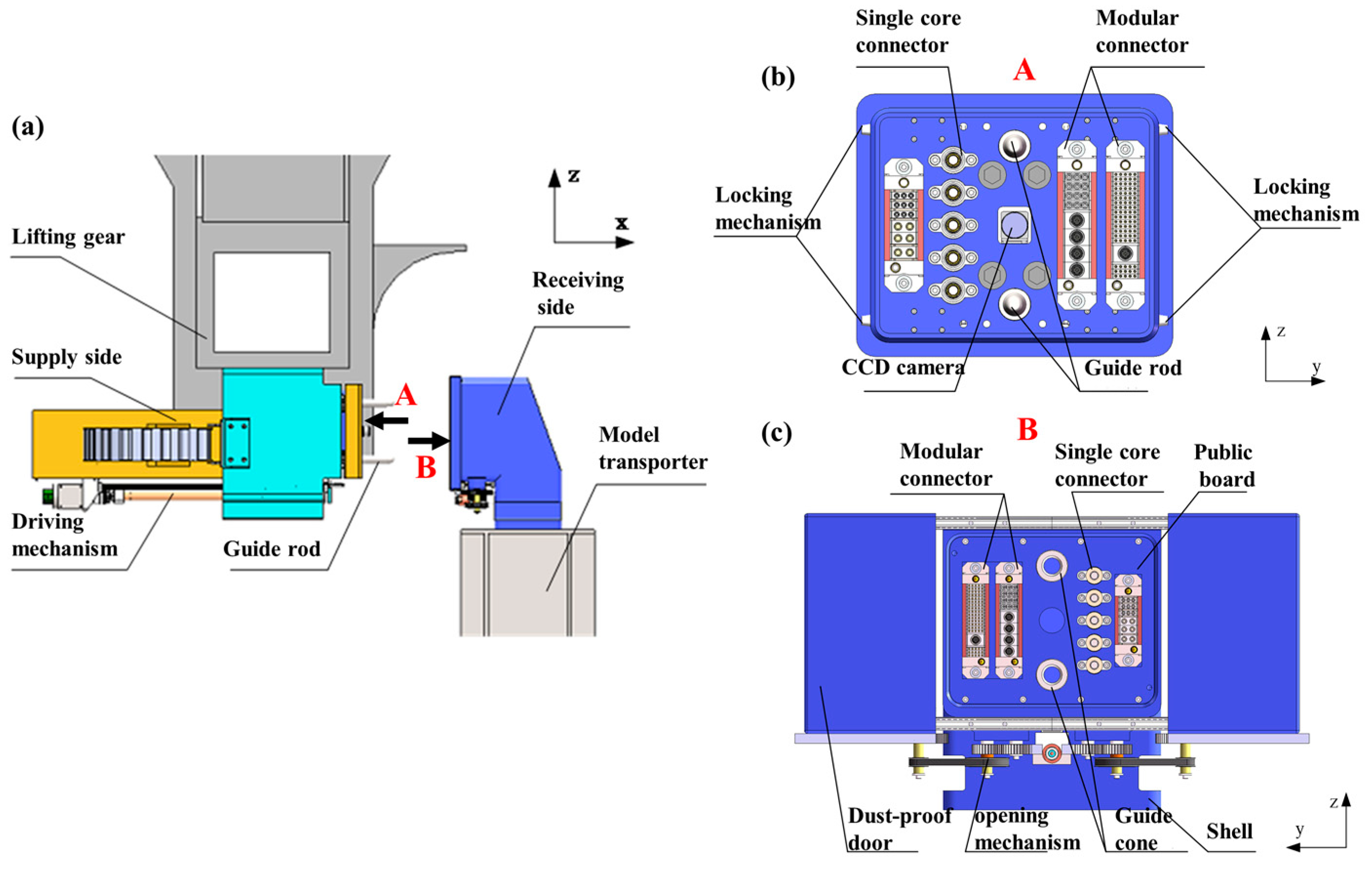
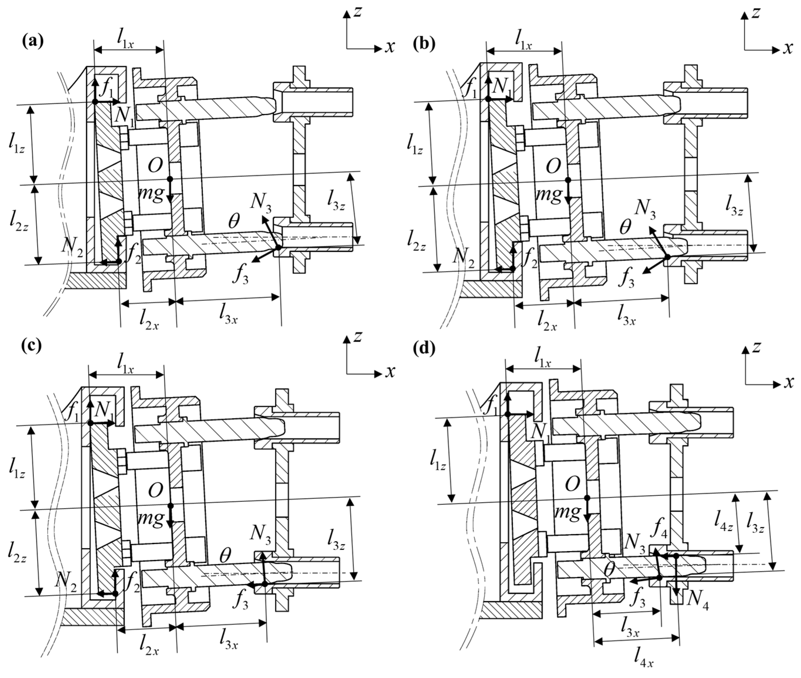
- The Pre-Alignment Phase: During this stage (Figure 2b), the adaptive mechanism locks the female panel to ensure precise insertion of the guide rod into the conical surface of the Guide Cone.
- (2)
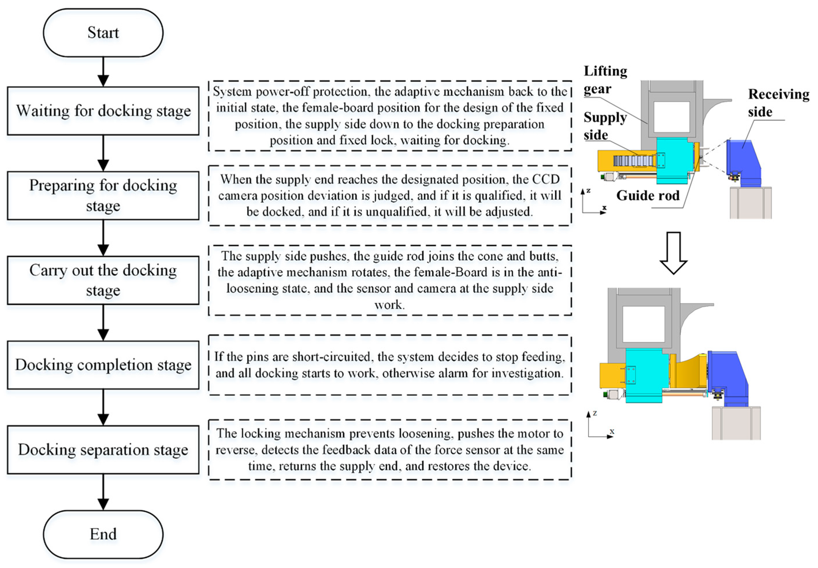
- The Compliant Adjustment Phase: Following guide pair engagement (Figure 2c), the female panel constraints are released, enabling the system to switch to compliant mode for pose adaptive correction. A dynamic force monitoring module continuously acquires contact force signals to prevent overload damage. The complete docking sequence is detailed in Figure 3.
- (1)
- The primary drive motor achieves positioning accuracy along the docking axis.
- (2)
- The adaptive mechanism regulates homing cone displacement through motorized lead screw actuation, enabling female panel fixation/release state transitions (Figure 2a). During guide pair coupling, the system autonomously compensates for initial pose deviations via geometric constraints, ensuring reliable connector engagement under low contact forces. This design synergizes multi-DOF cooperative control with modular interface integration, enhancing positioning reliability in complex operational scenarios compared to conventional systems.
2.2. Phased Contact State Analysis
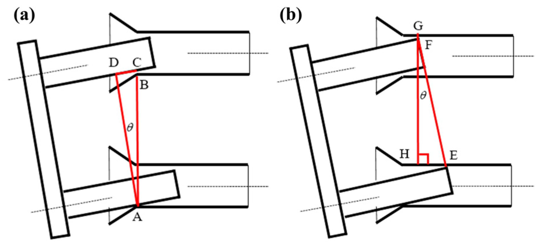
2.2.1. Geometric Discrimination Criteria
2.2.2. Four-Phase Dynamic Force Modeling
- (1)
- First Fillet Phase
- (2)
- Second Fillet Phase
- (3)
- Single-Point Contact Phase
- (4)
- Two-Point Contact Phase
3. Dynamic Wear Threshold and Modified Archard Theory
3.1. Functional Failure Criteria
3.2. Wear Depth Model Based on Archard Model
4. Finite Element Simulation Methodology Based on ABAQUS
4.1. Material Properties and Boundary Conditions
- (1)
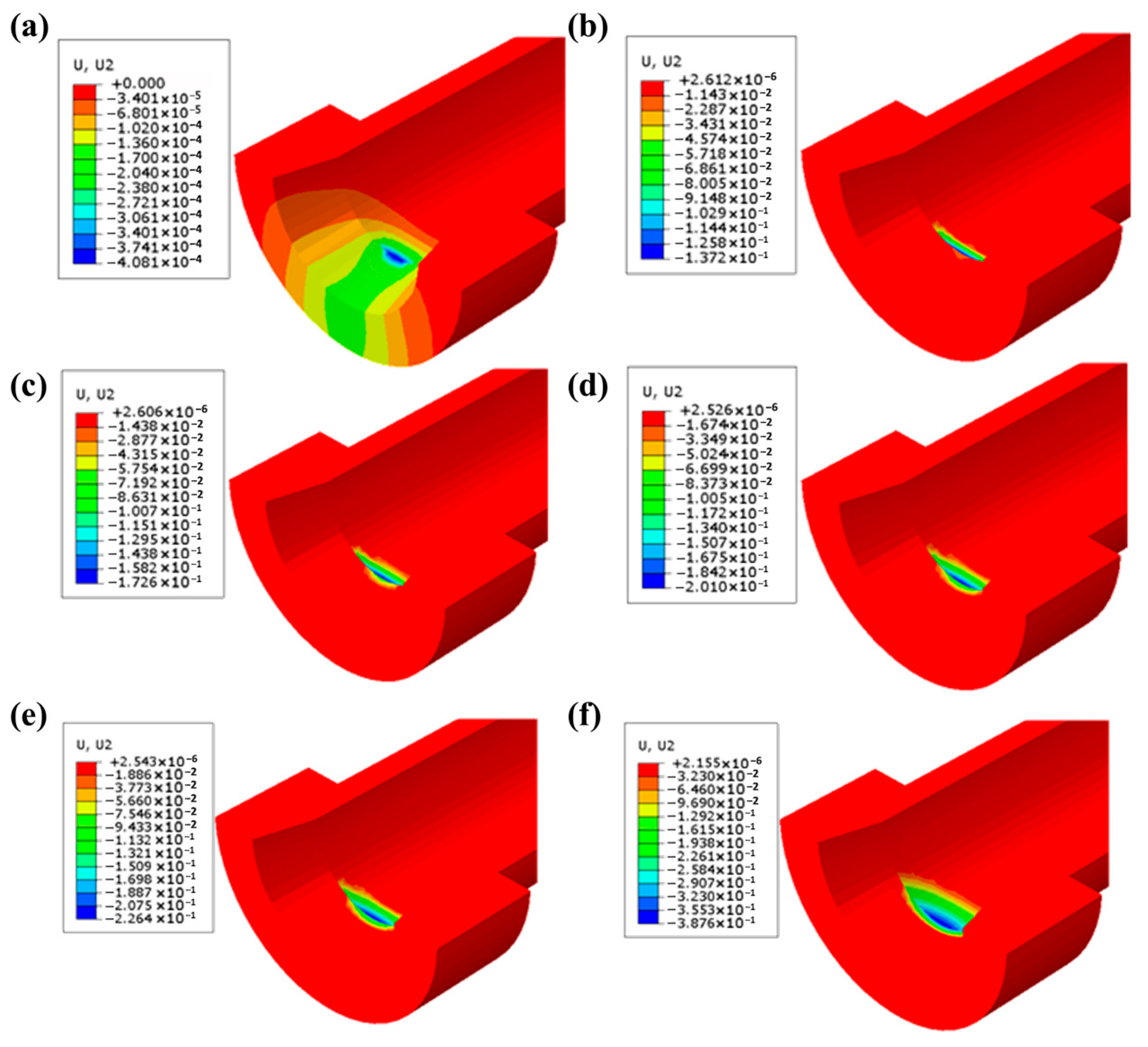
- Normal loads are applied along the guide rod’s contact point extension line, derived from prior contact force calculations.
- (2)
- Guide rod motion is constrained in X/Z directions (Ux = Uz = 0) with all rotational degrees of freedom fixed (URx = URy = URz = 0).
- (3)
- The Guide Cone is fully constrained at its base to simulate fixation on the male panel, eliminating rigid body displacements while preserving Y-axis mobility for docking simulation.
4.2. Computational Framework Implementation
5. Experimental Validation
- (1)
- Baseline Parameter Measurement: A digital micrometer (1 μm resolution) is used to perform quintuple axial measurements at predetermined wear zones of the Guide Cone, with triplicate circumferential sampling (120° intervals) per axial position; 3σ-filtered mean values establish baseline inner diameters.
- (2)
- Laser displacement sensors calibrate the receiver pose to meet spatial constraints: ΔY ≤ 3 mm; ΔZ ≤ 3 mm. Gravity-induced constant contact between guide components ensures wear consistency across initial pose variations.
- (3)
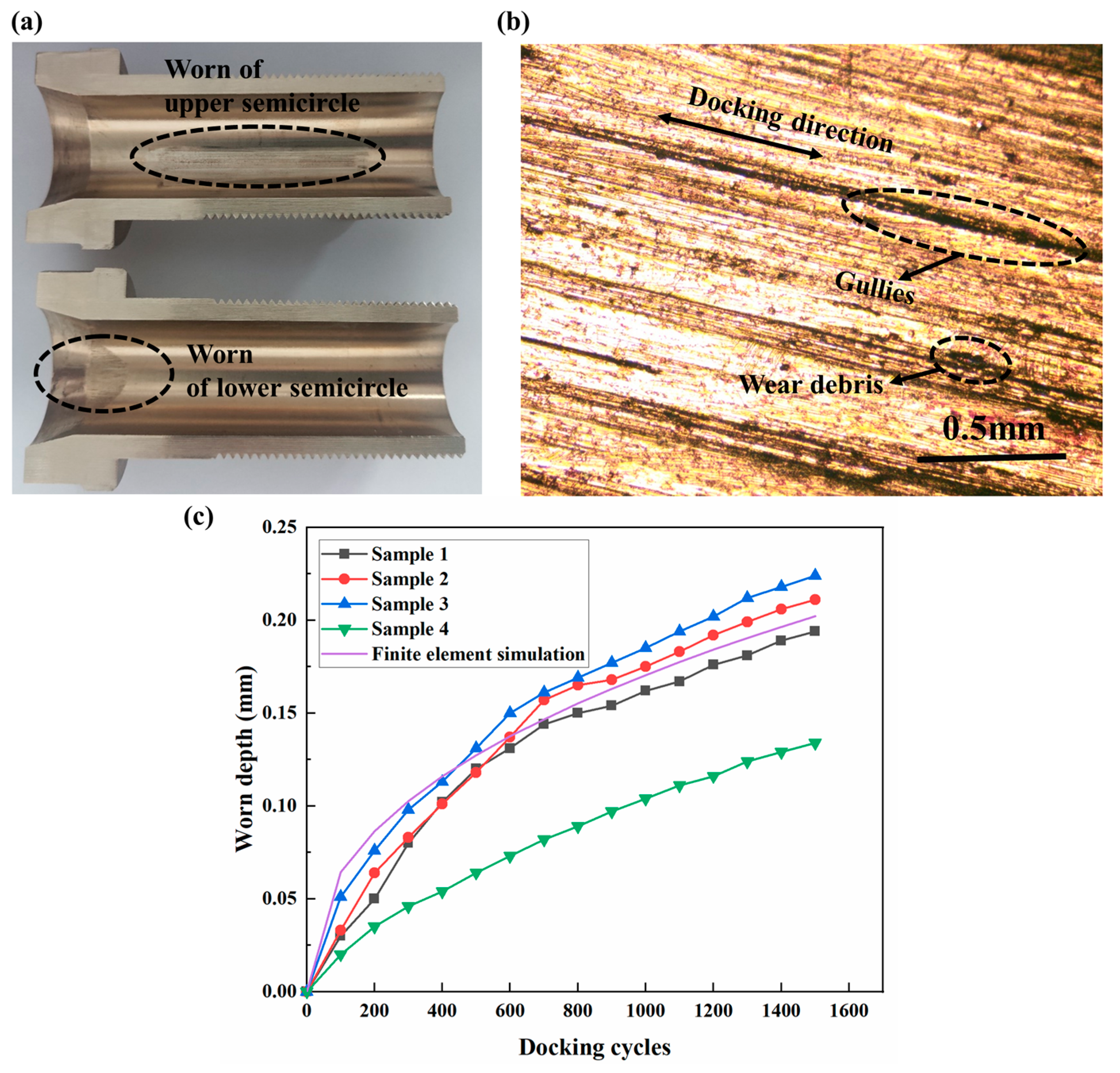
- Cyclic Docking Test: Each specimen undergoes 1500 standardized docking cycles (1.2 mm/s speed). Wear depth is quantified every 100 cycles through replicated baseline measurement protocols.
- (4)
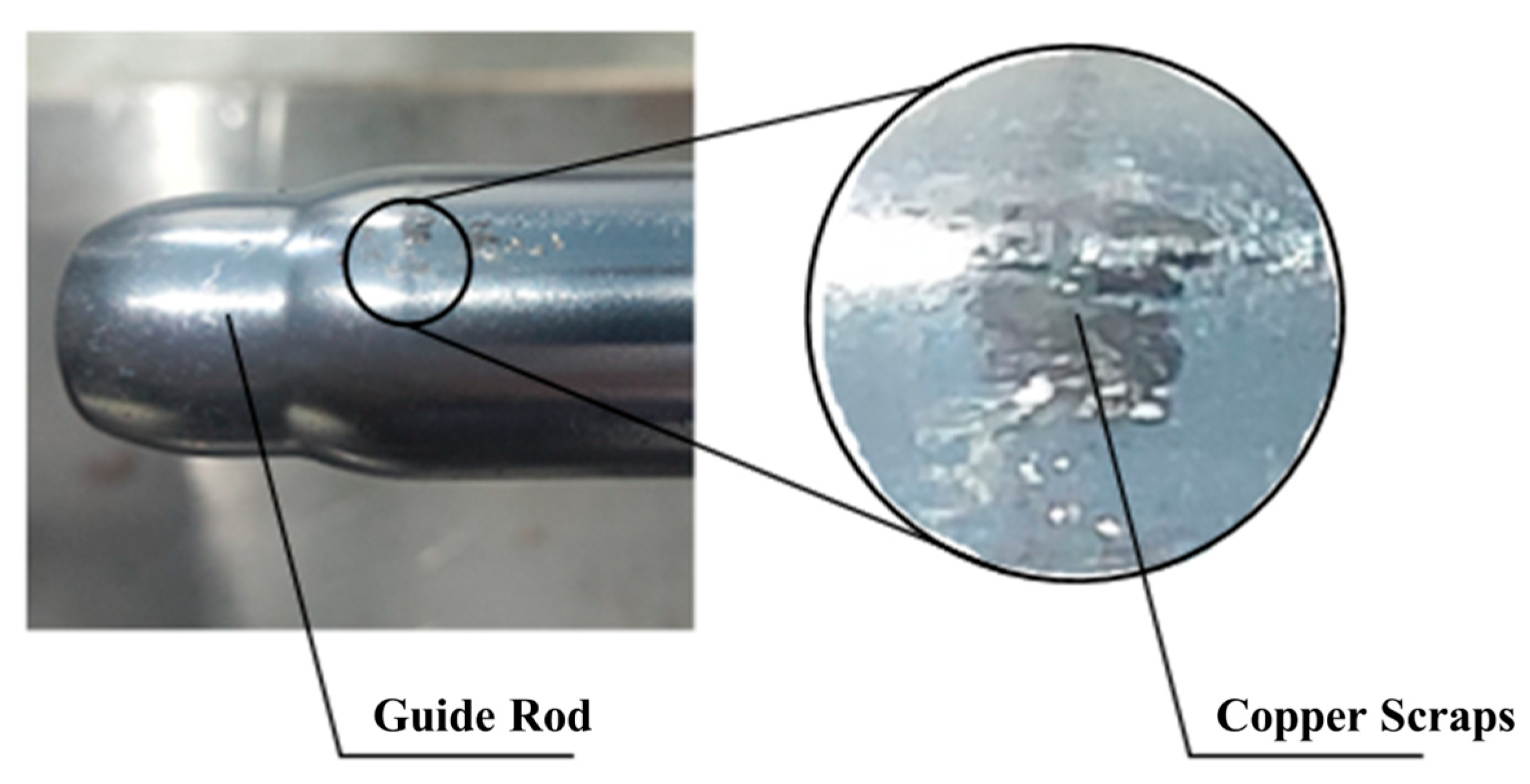
- Wear Mechanism Investigation: Post-test specimens are sectioned via wire EDM and analyzed using metallurgical microscopy (VHX6000, KEYENCE, Osaka, Japan) for wear morphology characterization.
6. Results and Discussion
6.1. Finite Element Simulation Results of Guide Cone Wear
6.2. Wear Mechanism Interpretation
6.3. Model Accuracy Assessment
7. Model Validation and Life Prediction
7.1. Life Verification
7.2. Model Limitations and Enhancement Methodologies
7.2.1. Constraints in Theoretical Framework
7.2.2. Pathways to Extended Docking System Service Life
8. Conclusions
- (1)
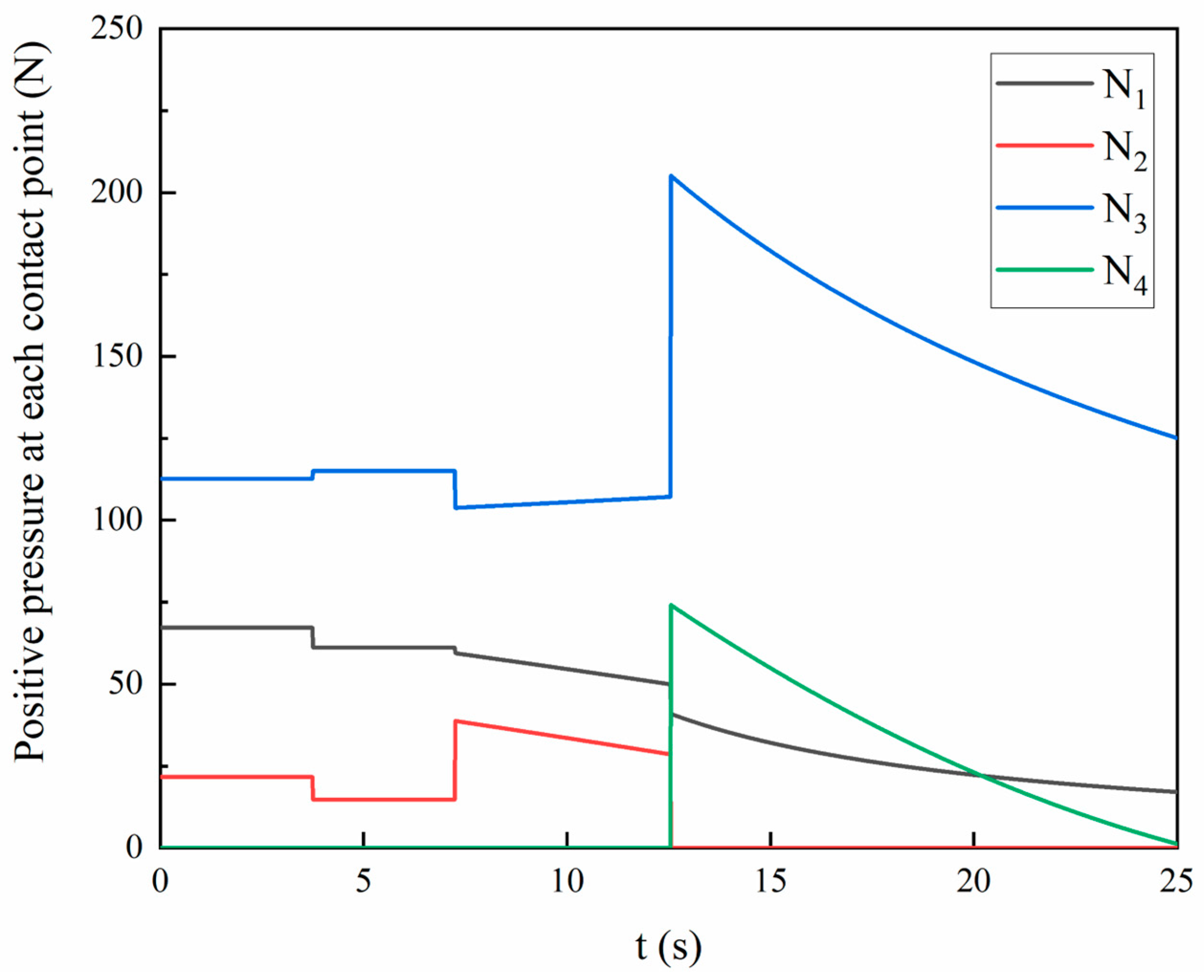
- The evolutionary patterns of dynamic contact loads on Guide Cones are elucidated through the establishment of phased contact state criteria and geometric constraints. By analyzing force equilibrium relationships during the four-phase engagement process, transient load characteristics are quantified with peak contact forces reaching 206.34 N, establishing a mechanical foundation for dynamic wear modeling.
- (2)
- An iterative Archard algorithm incorporating dynamic contact stress integration is developed, creating a bidirectional wear morphology–stress coupling simulation framework. Utilizing ABAQUS/Standard with ALE adaptive meshing, discrete wear depth calculations reveal an exponential decay relationship between cumulative wear depth and docking cycles, achieving a predicted service life of 45,270 cycles for bronze alloy cone systems.
- (3)
- Prototype testing demonstrates strong agreement between simulated and measured wear depths, with a mean absolute percentage error of 14.6%. Metallographic analysis confirms adhesive wear as the dominant mechanism, showing a 42.99% wear rate reduction in QSn6-6-3 (HV 242.8) compared to ZQSn5-2 (HV 213.77).
- (4)
- The cumulative wear-based life assessment verifies that 45,270 cycles at the 0.8 mm critical threshold exceed 50-year requirements (30,000 cycles) with a 50.9% safety margin, outperforming conventional empirical approaches. Polymer composites emerge as the highest-potential solution for extending the service life of Guide Cones: compared to metal, the cyclic life of carbon-fiber-reinforced PEEK systems has been increased by 200%, achieved through order-of-magnitude lower wear rates (10−7–10−6 mm3/(N·m)). This positions polymer optimization as the pivotal strategy for next-generation docking systems. Future work will prioritize experimental validation of polymer composites, with a parallel investigation of multi-factor mechanisms (temperature-dependent crystallinity and fiber orientation effects) to unlock their full lifespan potential.
Author Contributions
Funding
Institutional Review Board Statement
Data Availability Statement
Conflicts of Interest
Abbreviations
| ALE | Arbitrary Lagrangian–Eulerian |
| MAPE | Mean Absolute Percentage Error |
| DOF | Degree of Freedom |
| VSV | Variable Stator Vane |
References
- Lei, X.; Feng, C.; Lv, W.; Zhou, Y.; Xiong, C.; Gao, Y.; Zhu, F. Electrical contact reliability investigation of high-speed electrical connectors under fretting wear behavior. Microelectron. Reliab. 2024, 162, 115510. [Google Scholar] [CrossRef]
- Luo, Y.; Gao, P.; Liang, H.; Sun, Z. Application of Ultrasonic Testing Technology to Fretting Wear Detection of Electrical Connectors. IEEE Trans. Compon. Packag. Manuf. Technol. 2021, 11, 922–930. [Google Scholar] [CrossRef]
- Beltran-Hernandez, C.C.; Petit, D.; Ramirez-Alpizar, I.G.; Nishi, T.; Kikuchi, S.; Matsubara, T.; Harada, K. Learning Force Control for Contact-Rich Manipulation Tasks With Rigid Position-Controlled Robots. IEEE Robot. Autom. Lett. 2020, 5, 5709–5716. [Google Scholar] [CrossRef]
- Chen, Y.; Xie, F.; Liu, X.; Zhou, Y. Error Modeling and Sensitivity Analysis of a Parallel Robot with SCARA(Selective Compliance Assembly Robot Arm) Motions. Chin. J. Mech. Eng. 2014, 27, 693–702. [Google Scholar] [CrossRef]
- Lin, Q.; Zhang, M.; Ren, J.; Hua, Q. Investigation on a new type of latching mechanism on the satellite-rocket docking system and locking dynamic analysis. Proc. Inst. Mech. Eng. Part G-J. Aerosp. Eng. 2023, 237, 992–1003. [Google Scholar] [CrossRef]
- Sun, Z.C.; Zhang, H.; Shi, J.X.; Song, X.D. Mechanical modeling and parameter analysis of the docking process for probe-drogue docking mechanisms. Aerosp. Sci. Technol. 2024, 154, 109536. [Google Scholar] [CrossRef]
- Tian, F.; Lv, C.; Li, Z.; Liu, G. Modeling and control of robotic automatic polishing for curved surfaces. CIRP J. Manuf. Sci. Technol. 2016, 14, 55–64. [Google Scholar] [CrossRef]
- Jiang, J.; Zhang, X.; Tao, B.; Dong, Q. Design and experiment of remote handling motor replacement device based on passive compliant mechanism. J. Zhejiang University. Eng. Sci. 2021, 55, 855–865, 886. [Google Scholar] [CrossRef]
- Barrionuevo, G.O.; Calvopiña, H.; Debut, A.; Pérez-Salinas, C. Experimental and numerical investigation of sliding wear of heat-treated 316L stainless steel additively manufactured. J. Mater. Res. Technol. 2024, 33, 2692–2703. [Google Scholar] [CrossRef]
- Xiao, Y.; Yao, P.; Zhou, H.; Zhang, Z.; Gong, T.; Zhao, L.; Zuo, X.; Deng, M.; Jin, Z. Friction and wear behavior of copper matrix composite for spacecraft rendezvous and docking under different conditions. Wear 2014, 320, 127–134. [Google Scholar] [CrossRef]
- Kalidas, P.; Ramalingam, V.V.; Myilsamy, G.; Kasi, R.K.; Baghad, A. Numerical and experimental validation of tribological phenomenon in wind turbine brake pads using novel Archard’s wear coefficient. Proc. Inst. Mech. Eng. Part J-J. Eng. Tribol. 2024, 238, 1103–1120. [Google Scholar] [CrossRef]
- Aydin, F.; Durgut, R.; Mustu, M.; Demir, B. Prediction of wear performance of ZK60/CeO2 composites using machine learning models. Tribol. Int. 2023, 177, 107945. [Google Scholar] [CrossRef]
- Harnafi, M.; Guidault, P.-A.; Boucard, P.-A.; Paleczny, C. A simplified model for the wear prediction of plain bearings in the variable stator vane system. Tribol. Int. 2024, 196, 109667. [Google Scholar] [CrossRef]
- Wang, Z.; Ye, R.; Singh, S.S.; Wu, S.; Zhao, X. Modelling and fatigue reliability investigation on wear prediction of piston/cylinder pair based on friction fatigue mechanism. Tribol. Int. 2024, 194, 109485. [Google Scholar] [CrossRef]
- Archard, J.F. Contact and Rubbing of Flat Surfaces. J. Appl. Phys. 1953, 24, 981–988. [Google Scholar] [CrossRef]
- Choudhry, J.; Almqvist, A.; Larsson, R. Improving Archard’s Wear Model: An Energy-Based Approach. Tribol. Lett. 2024, 72, 93. [Google Scholar] [CrossRef]
- Argatov, I.I.; Bae, J.W.; Chai, Y.S. A Simple Model for the Wear Accumulation in Partial Slip Hertzian Contact. Int. J. Appl. Mech. 2020, 12, 2050074. [Google Scholar] [CrossRef]
- Liu, Y.F.; Liskiewicz, T.W.; Beake, B. Dynamic changes of mechanical properties induced by friction in the Archard wear model. Wear 2019, 428, 366–375. [Google Scholar] [CrossRef]
- Suh, N.P. An overview of the delamination theory of wear. Wear 1977, 44, 1–16. [Google Scholar] [CrossRef]
- Jacobson, S.; Wallén, P.; Hogmark, S. Fundamental aspects of abrasive wear studied by a new numerical simulation model. Wear 1988, 123, 207–223. [Google Scholar] [CrossRef]
- Kapoor, A.; Franklin, F.J. Tribological layers and the wear of ductile materials. Wear 2000, 245, 204–215. [Google Scholar] [CrossRef]
- Flašker, J.; Fajdiga, G.; Glodež, S.; Hellen, T.K. Numerical simulation of surface pitting due to contact loading. Int. J. Fatigue 2001, 23, 599–605. [Google Scholar] [CrossRef]
- Franklin, F.J.; Widiyarta, I.; Kapoor, A. Computer simulation of wear and rolling contact fatigue. Wear 2001, 251, 949–955. [Google Scholar] [CrossRef]
- Mukras, S.; Kim, N.H.; Mauntler, N.A.; Schmitz, T.L.; Sawyer, W.G. Analysis of planar multibody systems with revolute joint wear. Wear 2010, 268, 643–652. [Google Scholar] [CrossRef]
- Hou, Y.; Zhang, M.; Nie, H. Analysis of Sensitive Parameters Affecting Unlocking Force of Finger Lock in Landing Gear. Int. J. Aerosp. Eng. 2021, 2021, 6652056. [Google Scholar] [CrossRef]
- Lu, C.; Yin, J.; Mo, J.; Wang, J. Accumulated wear degradation prediction of railway friction block considering the evolution of contact status. Wear 2022, 494–495, 204251. [Google Scholar] [CrossRef]
- Bao, H.; Zhang, C.; Hou, X.; Lu, F. Wear Characteristics of Different Groove-Shaped Friction Pairs of a Friction Clutch. Appl. Sci. 2021, 11, 284. [Google Scholar] [CrossRef]
- Bai, Z.; Ning, Z.; Zhou, J. Study on Wear Characteristics of Revolute Clearance Joints in Mechanical Systems. Micromachines 2022, 13, 1018. [Google Scholar] [CrossRef] [PubMed]
- Changlin, G. Archard’s Wear Design Calculation Model and Its Application Method. Lubr. Seal. 1990, 1, 14–23. [Google Scholar]
- GB/T 12444-2006; Metal Materials—Wear Test Method—Ring-on-Block Sliding Wear Test. Standards Press of China: Beijing, China, 2006.
- He, W.; Feng, Y.; Wu, S.; Wu, K.; Ye, J.; Wang, W. Numerical simulation on the effect of current intensity on electrical contact performance of electrical connectors subject to micro-slip wear. Wear 2024, 542–543, 205270. [Google Scholar] [CrossRef]
- Abdelgaied, A.; Brockett, C.L.; Liu, F.; Jennings, L.M.; Jin, Z.; Fisher, J. The effect of insert conformity and material on total knee replacement wear. Proc. Inst. Mech. Eng. Part H-J. Eng. Med. 2014, 228, 98–106. [Google Scholar] [CrossRef] [PubMed]
- He, Y.; Lin, B.; Wang, Y.; Zhao, F.; Ning, G.; Bao, X.; Sui, T. Effect of homologous molecular crosslinking on the tribological properties of PTFE composites. Polym. Compos. 2023, 44, 5132–5147. [Google Scholar] [CrossRef]
- He, Y.; Lin, B.; Wang, Y.; Zhao, F.; Yan, S.; Ning, G.; Bao, X.; Li, H.; Sui, T. Hybrid reinforcing effect of multi-scale short carbon fibers on the wear resistance of PTFE composites: Self-reconstruction and stress transmission. Tribol. Int. 2024, 194, 109510. [Google Scholar] [CrossRef]
- Zhao, F.; He, Y.; Lin, B.; Wang, Y.; Sui, T.; Lin, W.; Fang, L.; Liao, M. Investigation of Wear Mechanisms in Multi-Scale Short Carbon Fiber Reinforced PTFE Composites for Blade Rotor Volumetric Pumps in Variable Lubrications. Polym. Compos. 2025, 1–17. [Google Scholar] [CrossRef]
- Zhang, K.; Lin, Z.; Ma, S.; Pan, S.; Chen, W.; Wang, D.; Chen, C.; Zhao, X. Silver with tribo-chemistry facilitation synergized with graphite particles for enhancing the tribo-performance of PEEK composites. Compos. Part A-Appl. Sci. Manuf. 2024, 187, 108456. [Google Scholar] [CrossRef]
- Maslavi, A.; Unal, H.; Olabi, M.N. Determination of “tribological performance working fields” for pure PEEK and PEEK composites under dry sliding conditions. Wear 2024, 554–555, 205464. [Google Scholar] [CrossRef]
- Bharatish, A.; Harish, V.; Bathe, R.N.; Senthilselvan, J.; Soundarapandian, S. Effect of scanning speed and tin content on the tribological behavior of femtosecond laser textured tin-bronze alloy. Opt. Laser Technol. 2018, 108, 17–25. [Google Scholar] [CrossRef]



| Material | Elastic Modulus E (GPa) | Poisson’s Ratio v | Vickers Hardness HV | Brinell Hardness HB | |
|---|---|---|---|---|---|
| Guide rod | 40Cr | 211 | 0.3 | ||
| Guide cone | ZQSn5-2 | 103 | 0.3 | 213.77 ± 3.26 | 202.77 ± 3.26 |
| Docking Cycles | Cumulative Wear Depth (mm) | Docking Cycles | Cumulative Wear Depth (mm) |
|---|---|---|---|
| 1 | 4.08 × 10⁻⁴ | 1000 | 0.173 |
| 50 | 3.29 × 10⁻² | 2000 | 0.226 |
| 100 | 5.32 × 10⁻² | 3000 | 0.267 |
| 200 | 8.37 × 10⁻² | 4000 | 0.303 |
| 300 | 0.11 | 5000 | 0.335 |
| 400 | 0.128 | 6000 | 0.362 |
| 500 | 0.137 | 7000 | 0.388 |
| Docking Cycles | Sample 1 | Sample 2 | Sample 3 | Sample 4 | ||||
|---|---|---|---|---|---|---|---|---|
| Inside Diameter (mm) | Cumulative Wear Depth (mm) | Inside Diameter (mm) | Cumulative Wear Depth (mm) | Inside Diameter (mm) | Cumulative Wear Depth (mm) | Inside Diameter (mm) | Cumulative Wear Depth (mm) | |
| 0 | 26.031 | 0 | 26.018 | 0 | 26.034 | 0 | 26.030 | 0 |
| 100 | 26.061 | 0.030 | 26.051 | 0.033 | 26.085 | 0.051 | 26.050 | 0.020 |
| 200 | 26.081 | 0.050 | 26.082 | 0.064 | 26.11 | 0.076 | 26.065 | 0.035 |
| 300 | 26.111 | 0.080 | 26.101 | 0.083 | 26.132 | 0.098 | 26.076 | 0.046 |
| 400 | 26.133 | 0.102 | 26.119 | 0.101 | 26.147 | 0.113 | 26.084 | 0.054 |
| 500 | 26.151 | 0.120 | 26.136 | 0.118 | 26.165 | 0.131 | 26.094 | 0.064 |
| 600 | 26.161 | 0.131 | 26.155 | 0.137 | 26.184 | 0.150 | 26.103 | 0.073 |
| 700 | 26.175 | 0.144 | 26.175 | 0.157 | 26.195 | 0.161 | 26.112 | 0.082 |
| 800 | 26.181 | 0.150 | 26.183 | 0.165 | 26.203 | 0.169 | 26.119 | 0.089 |
| 900 | 26.185 | 0.154 | 26.186 | 0.168 | 26.211 | 0.177 | 26.127 | 0.097 |
| 1000 | 26.193 | 0.162 | 26.193 | 0.175 | 26.219 | 0.185 | 26.134 | 0.104 |
| 1100 | 26.198 | 0.167 | 26.201 | 0.183 | 26.228 | 0.194 | 26.141 | 0.111 |
| 1200 | 26.207 | 0.176 | 26.210 | 0.192 | 26.236 | 0.202 | 26.146 | 0.116 |
| 1300 | 26.212 | 0.181 | 26.217 | 0.199 | 26.246 | 0.212 | 26.154 | 0.124 |
| 1400 | 26.220 | 0.189 | 26.224 | 0.206 | 26.252 | 0.218 | 26.159 | 0.129 |
| 1500 | 26.225 | 0.194 | 26.229 | 0.211 | 26.258 | 0.224 | 26.164 | 0.134 |
Disclaimer/Publisher’s Note: The statements, opinions and data contained in all publications are solely those of the individual author(s) and contributor(s) and not of MDPI and/or the editor(s). MDPI and/or the editor(s) disclaim responsibility for any injury to people or property resulting from any ideas, methods, instructions or products referred to in the content. |
© 2025 by the authors. Licensee MDPI, Basel, Switzerland. This article is an open access article distributed under the terms and conditions of the Creative Commons Attribution (CC BY) license (https://creativecommons.org/licenses/by/4.0/).
Share and Cite
He, Y.; Wang, B.; Zhao, F.; Hong, X.; Fang, L.; Xu, W.; Liao, M.; Tian, F. Dynamic Wear Modeling and Experimental Verification of Guide Cone in Passive Compliant Connectors Based on the Archard Model. Polymers 2025, 17, 2091. https://doi.org/10.3390/polym17152091
He Y, Wang B, Zhao F, Hong X, Fang L, Xu W, Liao M, Tian F. Dynamic Wear Modeling and Experimental Verification of Guide Cone in Passive Compliant Connectors Based on the Archard Model. Polymers. 2025; 17(15):2091. https://doi.org/10.3390/polym17152091
Chicago/Turabian StyleHe, Yuanping, Bowen Wang, Feifei Zhao, Xingfu Hong, Liang Fang, Weihao Xu, Ming Liao, and Fujing Tian. 2025. "Dynamic Wear Modeling and Experimental Verification of Guide Cone in Passive Compliant Connectors Based on the Archard Model" Polymers 17, no. 15: 2091. https://doi.org/10.3390/polym17152091
APA StyleHe, Y., Wang, B., Zhao, F., Hong, X., Fang, L., Xu, W., Liao, M., & Tian, F. (2025). Dynamic Wear Modeling and Experimental Verification of Guide Cone in Passive Compliant Connectors Based on the Archard Model. Polymers, 17(15), 2091. https://doi.org/10.3390/polym17152091


