
Improvements to Load-Bearing Capacity and Settlement of Clay Soil After Adding Nano-MgO and Fibers

Abstract
1. Introduction
2. Materials and Methods
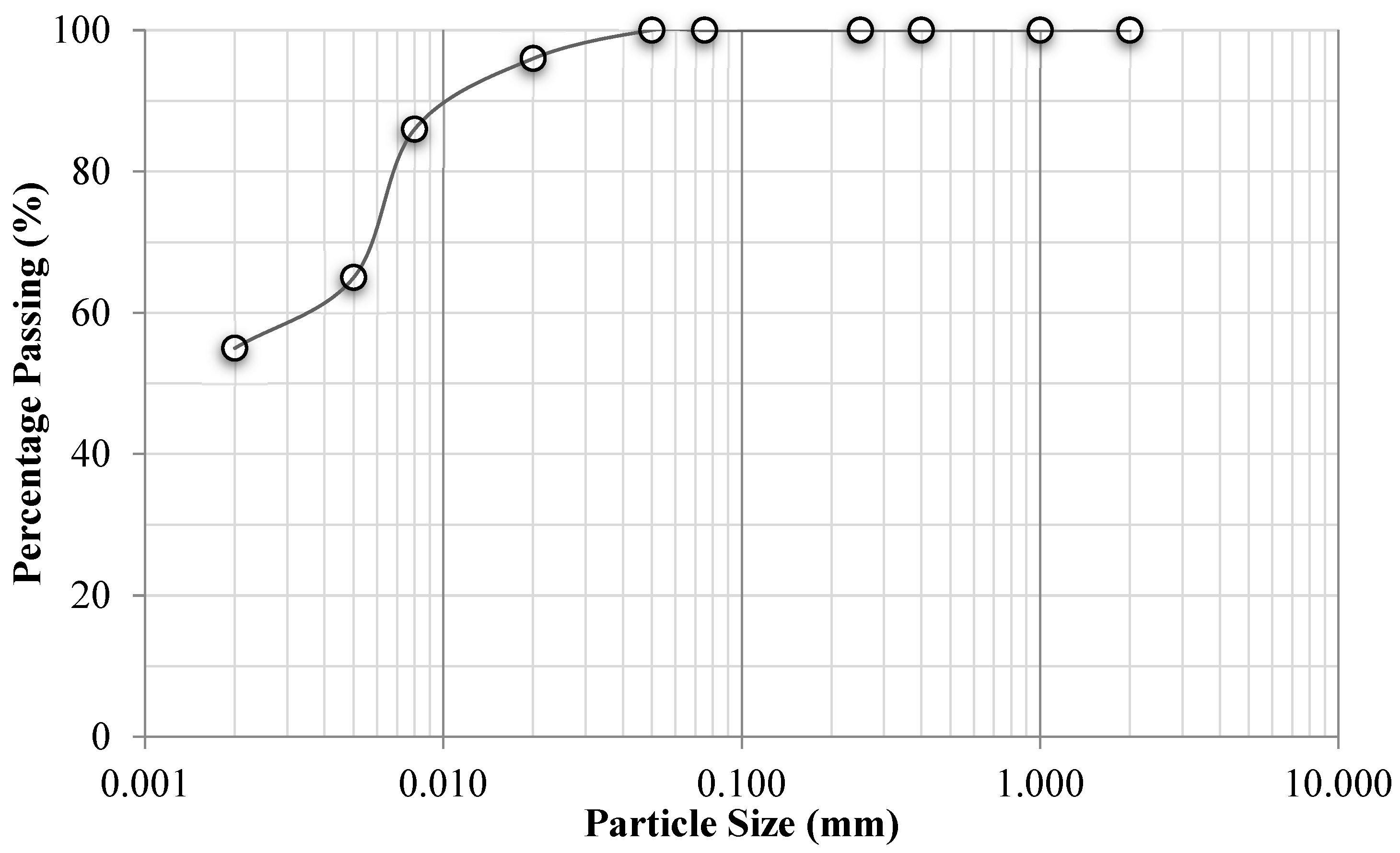
2.1. Materials
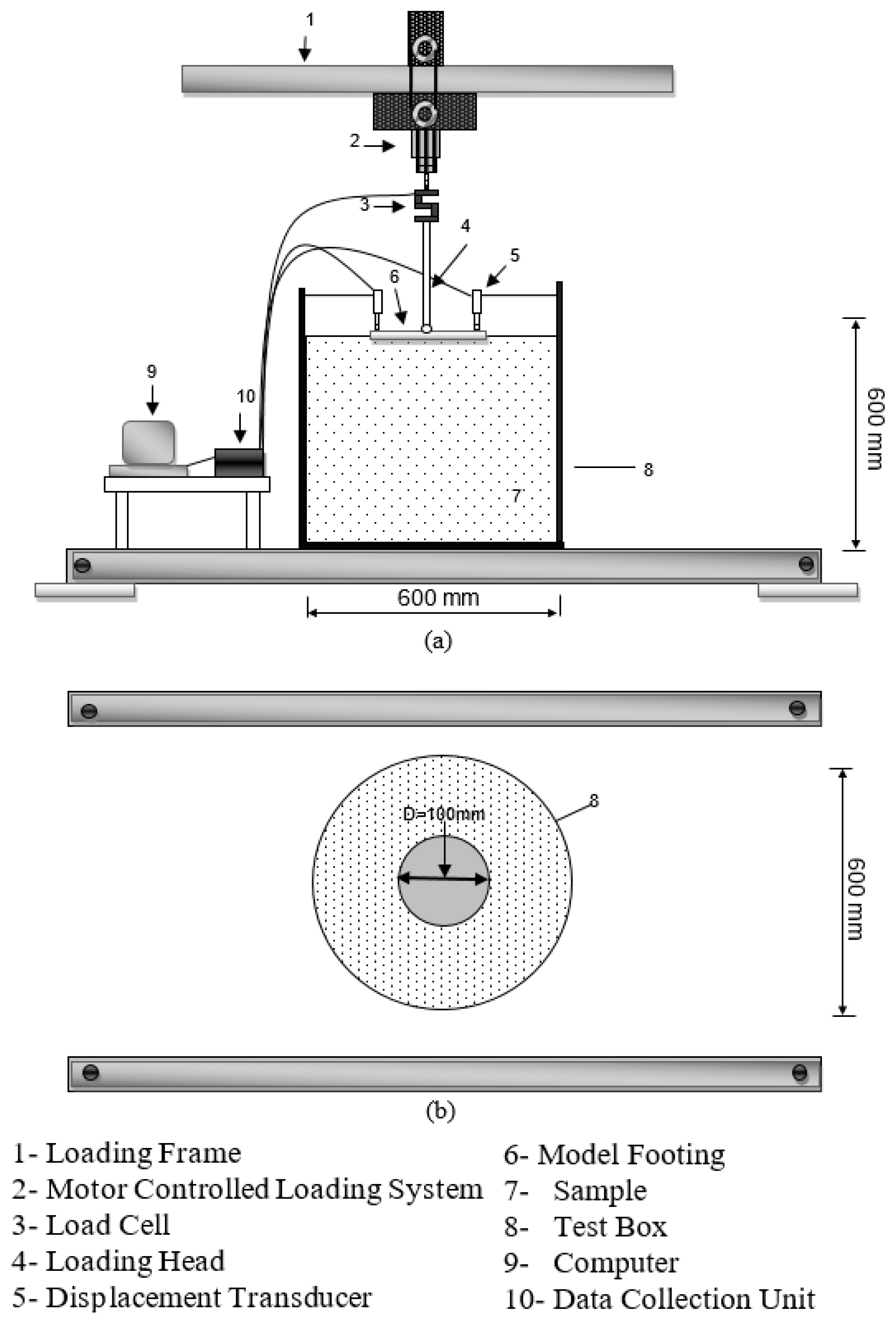
2.2. Methods
3. Results
3.1. Effects of Water Content and Mixing Ratio
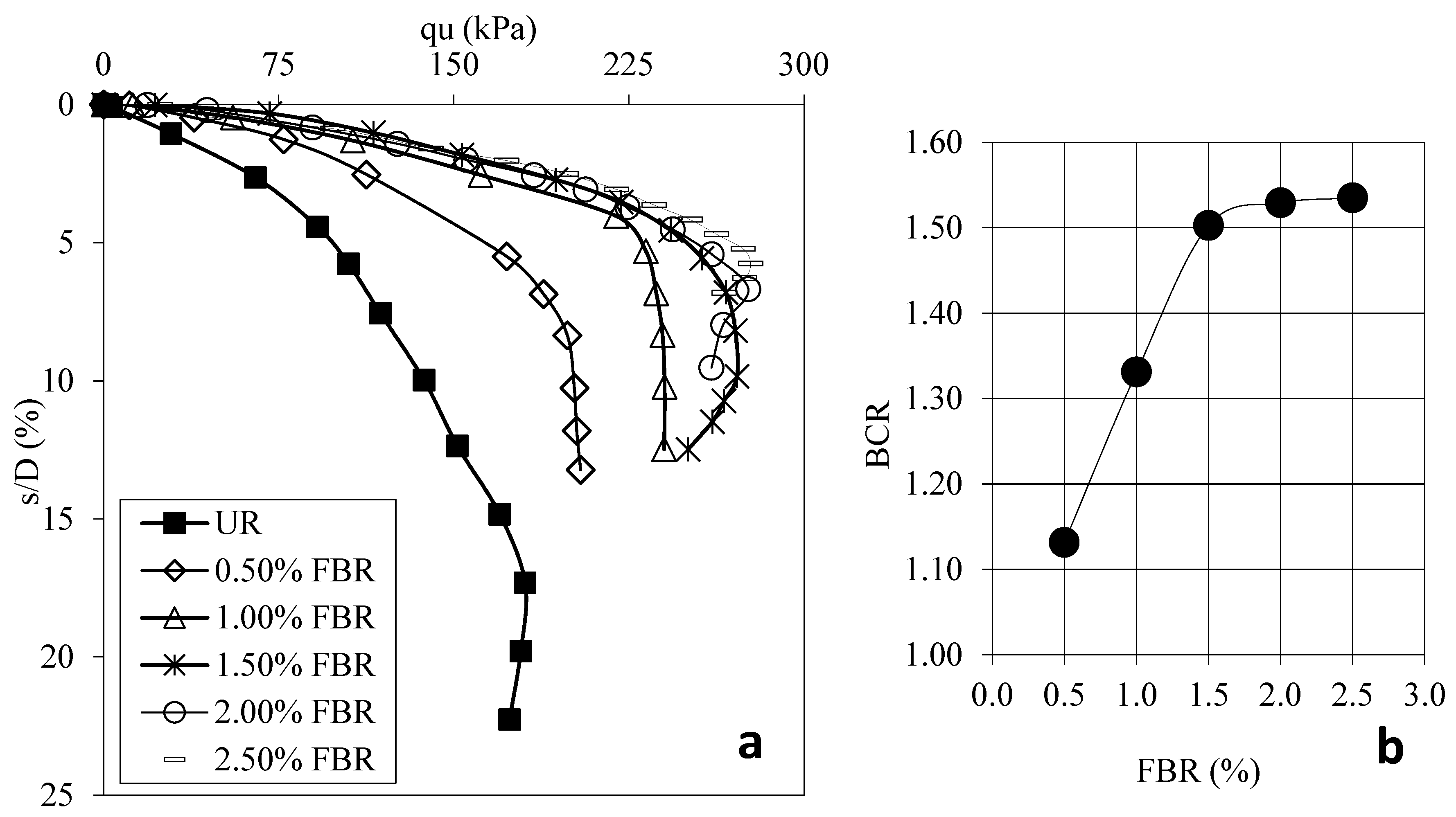
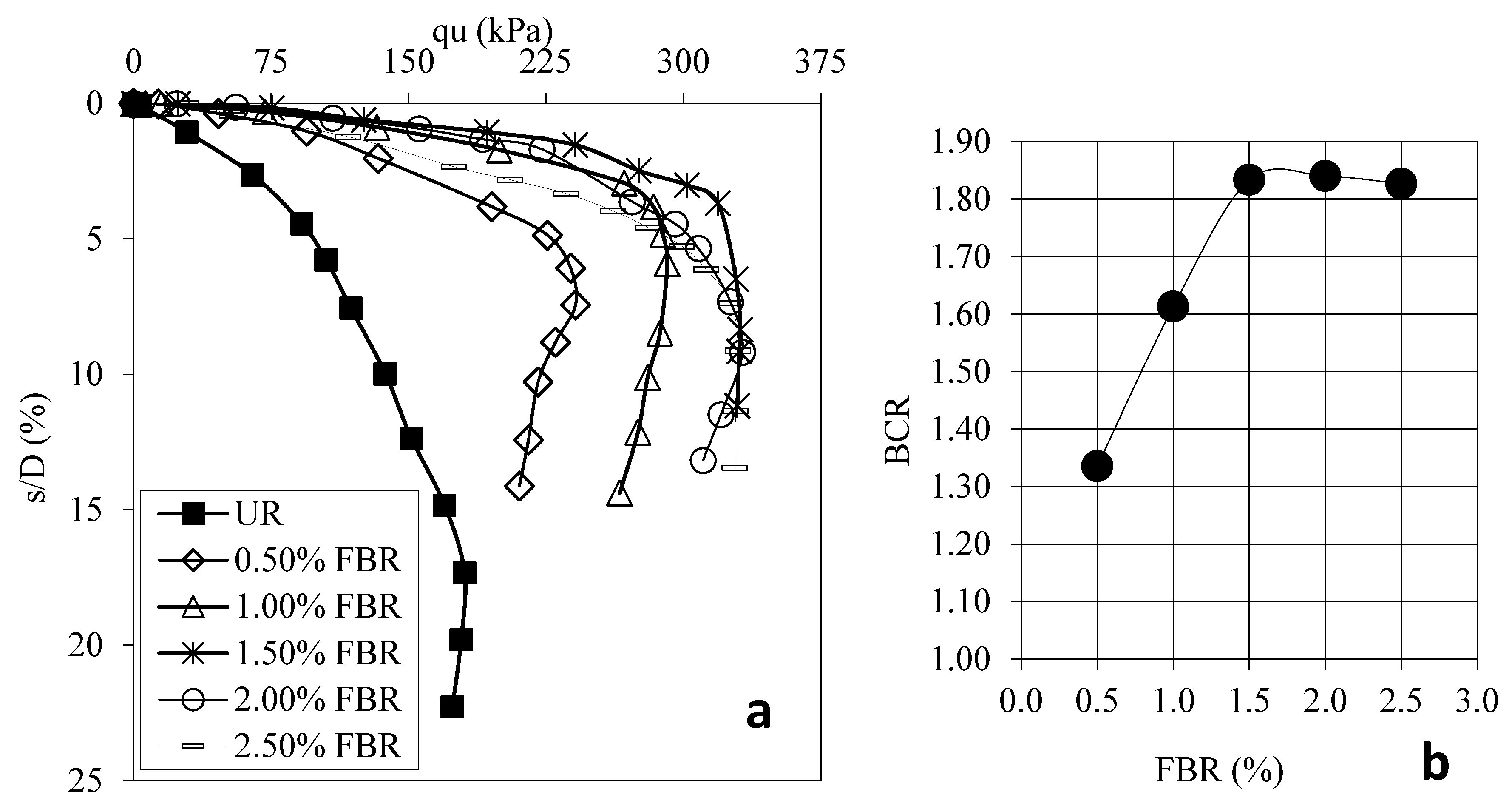
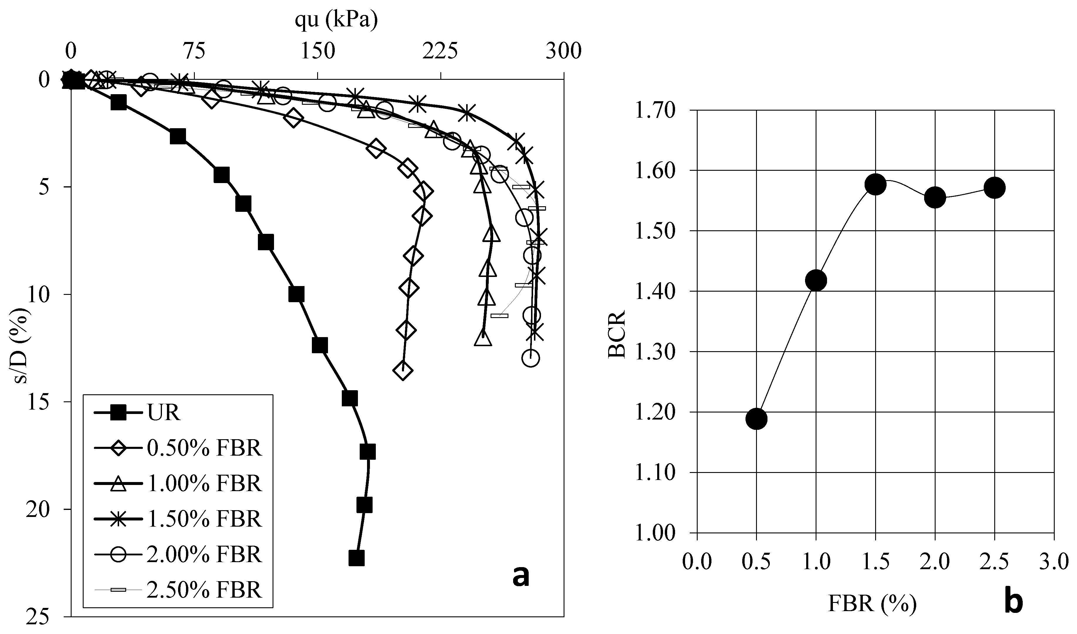
3.2. Effect of Fiber (FBR)
3.3. Effect of Nano-MgO (NM)
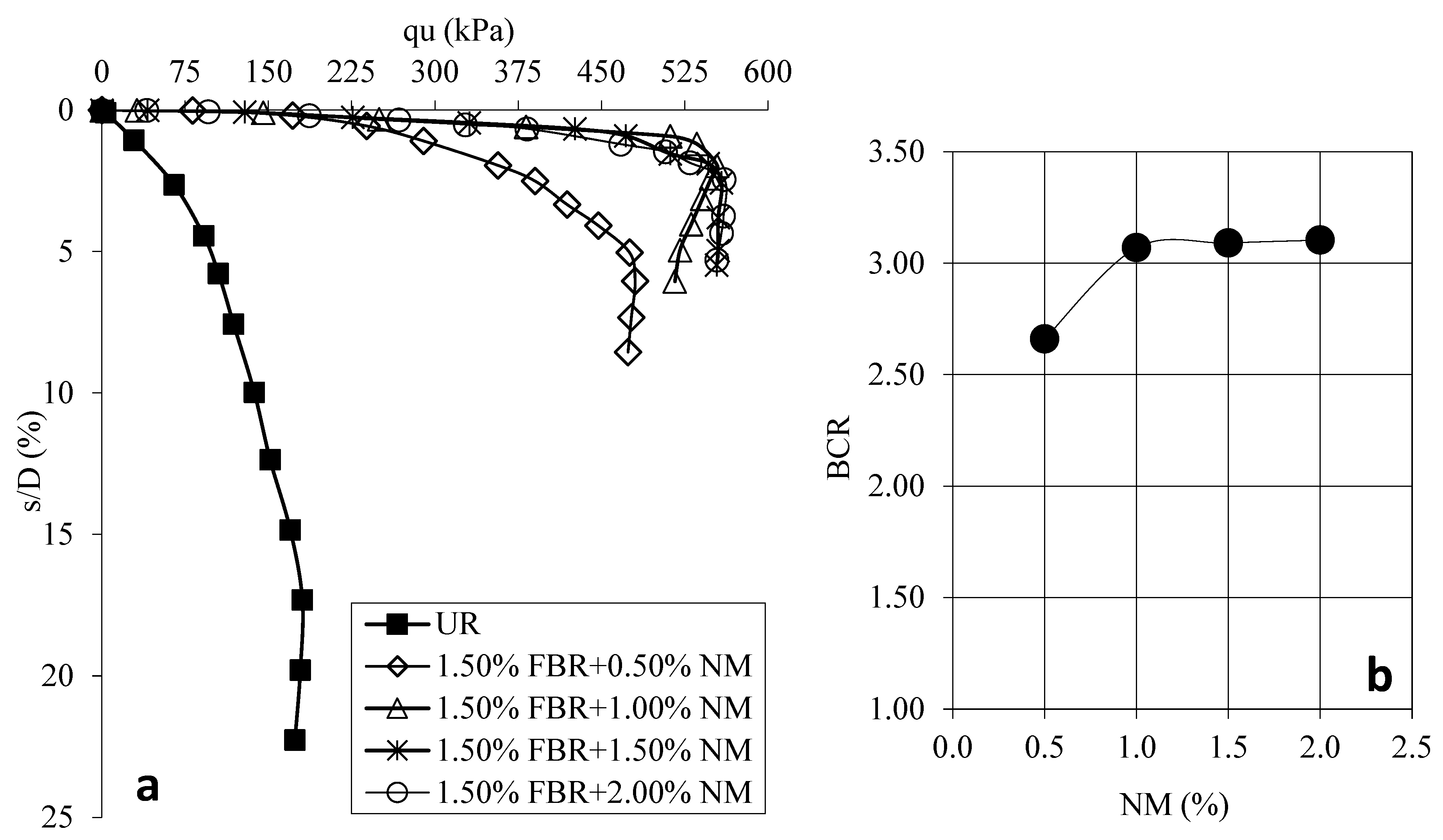
3.4. Effect of Nano-MgO (NM) with FBR
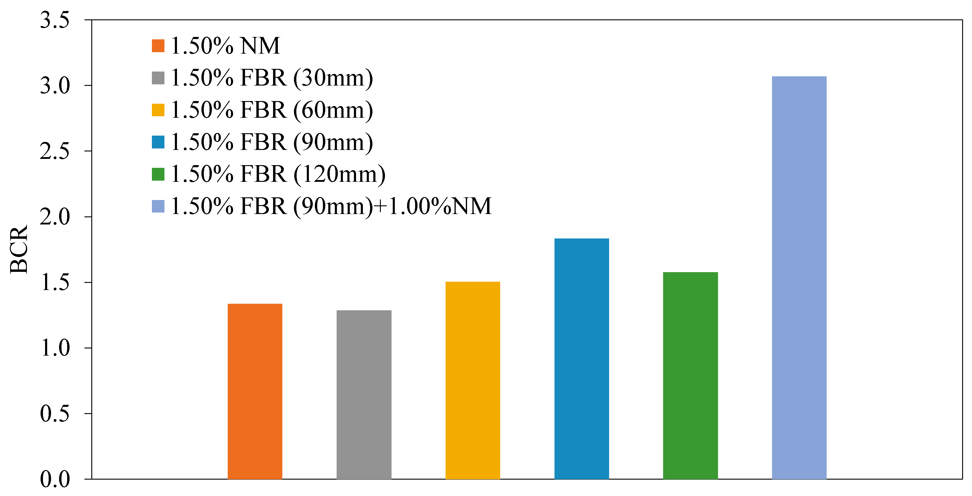
3.5. Overall Representation for NM and FBR Implementation
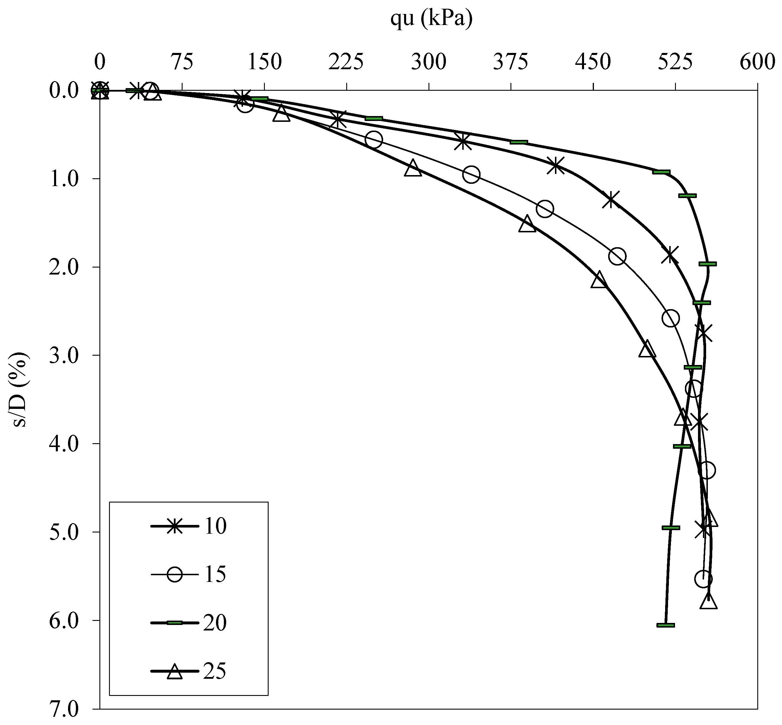
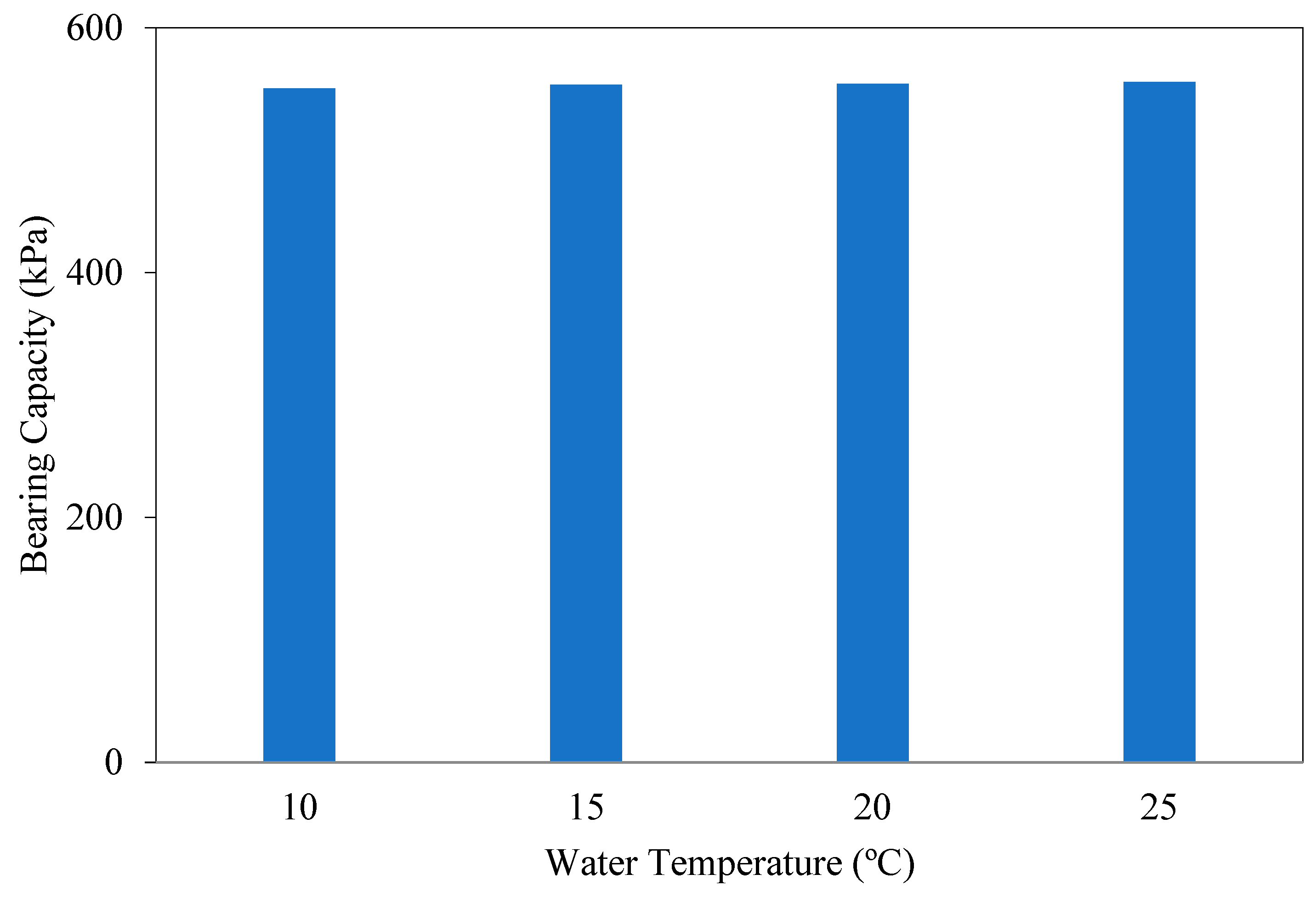
3.6. Effect of the Temperature of Mixing Water
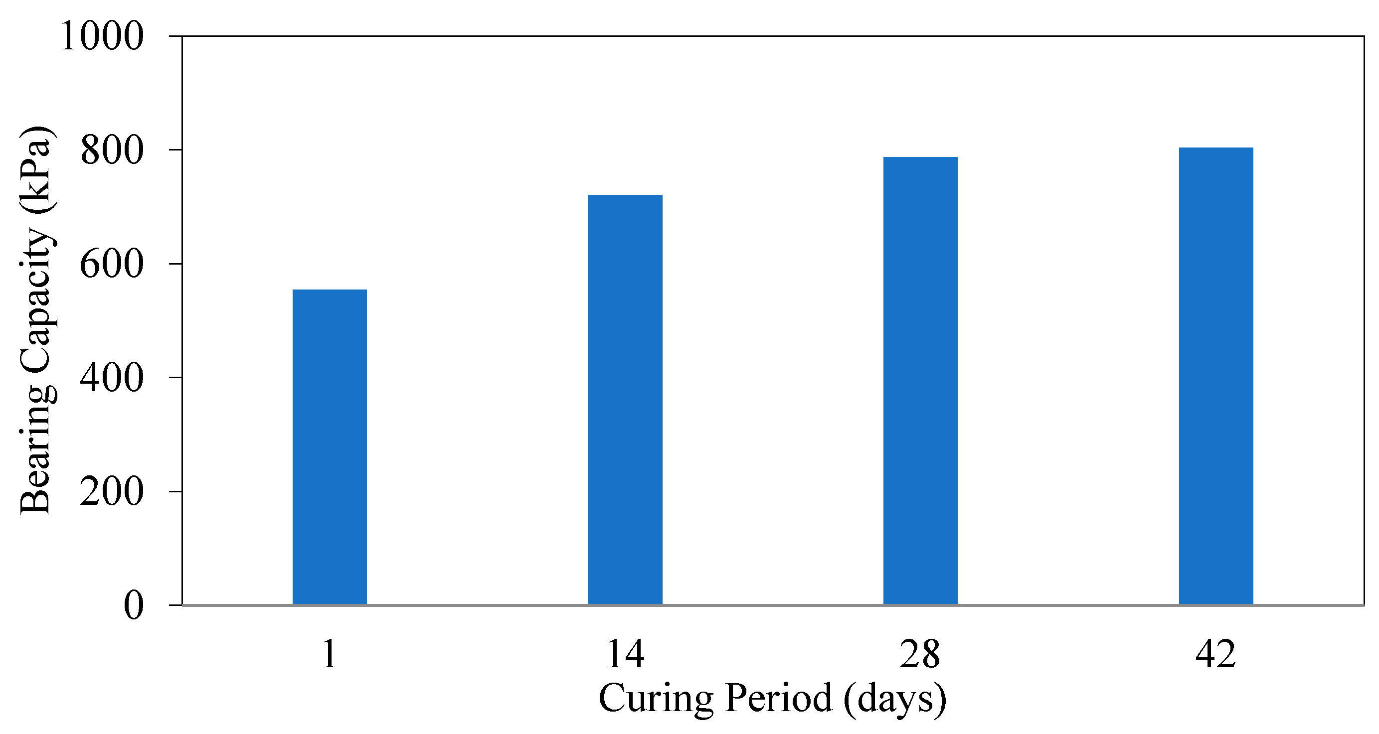
3.7. Effect of Curing Duration
4. Conclusions
- Optimal Fiber Parameters: The study determined that the optimum fiber length and volumetric content were 90 mm and 1.5%, respectively. At these parameters, the unconfined compressive strength (UCS) of the treated clay increased by approximately 1.83 times compared to untreated soil. These fiber dimensions promote effective load transfer and crack bridging within the soil matrix, while remaining practical for mixing and cost-effective for large-scale applications.
- NM Dosage Effects: When NM was added as the sole additive, the ideal dosage was 1.5% by weight. At this concentration, the bearing capacity improved by up to 1.33 times relative to the untreated samples. The mechanism involves the pozzolanic reaction between NM and clay minerals, forming cementitious compounds such as magnesium silicate hydrate (M-S-H), which enhance soil stiffness and cohesion. However, NM alone did not yield significant reductions in settlement, indicating that strength gains do not fully translate into deformation control.
- Combined Use of NM and FBR: The synergistic effect of combining NM (at an optimized dosage of 1.0%) with FBR (1.5% content, 90 mm length) resulted in a substantial 3.07-fold increase in bearing capacity. The combination leverages both mechanical reinforcement from fibers and chemical stabilization from NM. NM improves the interfacial bonding between fibers and soil particles, enhancing stress transfer and mitigating microcrack propagation under load. This synergy leads to improved resistance against both compressive and tensile stresses, effectively controlling settlement and deformation.
- Influence of Mixing Water Temperature: The experiments showed that varying the temperature of the mixing water had no significant impact on the mechanical properties of the treated soils. This suggests that the hydration and pozzolanic reactions involving NM are relatively insensitive to temperature variations within the tested range, simplifying field conditions where precise temperature control is challenging.
- Effect of Curing Time: Prolonged curing duration positively influenced the development of bearing capacity and settlement reduction in samples with NM, reflecting the ongoing formation of cementitious phases over time. In contrast, fiber reinforcement effects were immediate and stable, showing minimal dependence on curing time. This indicates that while chemical stabilization requires time to mature, mechanical reinforcement provides instant structural benefits.
- In conclusion, this research demonstrates that a combined approach of mechanical reinforcement (FBRs) and chemical stabilization (NM) significantly improves the geotechnical performance of clay soils. The optimal ratios identified ensure both economic feasibility and practical applicability for soil improvement projects.
- This study demonstrated that the combined use of NM and FBR offers promising results not only under laboratory conditions but also for field applications in improving low-bearing-capacity clay soils; the fine particle size of NM enables homogeneous mixing with the soil, while fibers provide physical reinforcement, significantly enhancing both load-bearing capacity and settlement performance. Additionally, the effectiveness of these additives at low dosages supports the economic and environmental sustainability of the method, making it a viable and adaptable alternative for ground improvement across various soil conditions.
- Future research is recommended to focus on long-term performance analyses under different climatic and loading conditions, the modeling of data obtained from field applications, and the evaluation of the method’s effectiveness on other soil types.
Author Contributions
Funding
Institutional Review Board Statement
Data Availability Statement
Conflicts of Interest
References
- Mittal, R.K.; Gill, G. Sustainable application of waste tire chips and geogrid for improving load carrying capacity of granular soils. J. Clean. Prod. 2018, 200, 542–551. [Google Scholar]
- Abbaspour, M.; Aflaki, E.; Nejad, F.M. Reuse of waste tire textile fibers as soil reinforcement. J. Clean. Prod. 2019, 207, 1059–1071. [Google Scholar]
- Arora, S.; Kumar, A. Bearing capacity of strip footing resting on fibre-reinforced pond ash overlying soft clay. Innov. Infrastruct. Solut. 2019, 4, 34. [Google Scholar]
- Badrawi, E.F.; El-kady, M.S. Stabilizing soft clay using geo-foam beads and cement bypass dust. Undergr. Space 2019, 5, 292–297. [Google Scholar] [CrossRef]
- Bagriacik, B.; Mahmutluoglu, B. A new experimental approach to the improvement of sandy soils with construction demolition waste and cement. Arab. J. Geosci. 2020, 13, 539. [Google Scholar] [CrossRef]
- Brooks, R.M. Soil stabilization with fly ash and rice husk ash. Int. J. Res. Rev. Appl. Sci. 2009, 1, 209–217. [Google Scholar]
- Bağrıaçık, B.; Mahmutluoğlu, B. Model experiments on coarse-grained soils treated with xanthan gum biopolymer. Arab. J. Geosci. 2021, 14, 1621. [Google Scholar] [CrossRef]
- Pastor, J.L.; Tomás, R.; Cano, M.; Riquelme, A.; Gutiérrez, E. Evaluation of the improvement effect of limestone powder waste in the stabilization of swelling clayey soil. Sustainability 2019, 11, 679. [Google Scholar] [CrossRef]
- Phetchuay, C.; Horpibulsuk, S.; Suksiripattanapong, C.; Chinkulkijniwat, A.; Arulrajah, A.; Disfani, M.M. Calcium carbide residue: Alkaline activator for clay–fly ash geopolymer. Constr. Build. Mater. 2014, 69, 285–294. [Google Scholar]
- Salimi, M.; Ghorbani, A. Mechanical and compressibility characteristics of a soft clay stabilized by slag-based mixtures and geopolymers. Appl. Clay Sci. 2020, 184, 105390. [Google Scholar]
- Striprabu, S.; Taib, S.N.; Sad’on, N.M.; Fauziah, A. Chemical stabilization of Sarawak soil with class F fly ash. J. Eng. Sci. Technol. 2018, 13, 3029–3042. [Google Scholar]
- Yokohama, S.; Sato, A. Cyclic mechanical properties of sandy soils by mixing recycled asphalt pavement material. Int. J. GEOMATE 2019, 16, 41–47. [Google Scholar]
- Shafigh, P.; Bin Mahmud, H.; Jumaat, M.Z.; Zargar, M. Agricultural wastes as aggregate in concrete mixtures: A review. Constr. Build. Mater. 2014, 53, 110–117. [Google Scholar]
- Lam, C.W.; James, J.T.; McCluskey, R.; Arepalli, S.; Hunter, R.L. A review of carbon nanotube toxicity and assessment of potential occupational and environmental health risks. Crit. Rev. Toxicol. 2006, 36, 189–217. [Google Scholar]
- Huang, Y.; Wang, L. Experimental studies on nanomaterials for soil improvement: A review. Environ. Earth Sci. 2016, 75, 497. [Google Scholar] [CrossRef]
- Majeed, Z.H.; Taha, M.R. A review of stabilization of soils by using nanomaterials. Aust. J. Basic Appl. Sci. 2013, 7, 576–581. [Google Scholar]
- Bahmani, S.H.; Huat, B.B.; Asadi, A.; Farzadnia, N. Stabilization of residual soil using SiO2 nanoparticles and cement. Constr. Build. Mater. 2014, 64, 350–359. [Google Scholar]
- Changizi, F.; Haddad, A. Effect of nano-silica on the geotechnical properties of cohesive soil. Geotech. Geol. Eng. 2016, 34, 725–753. [Google Scholar] [CrossRef]
- Choobbasti, A.J.; Kutanaei, S.S. Microstructure characteristics of cement-stabilized sandy soil using nanosilica. J. Rock Mech. Geotech. Eng. 2017, 9, 981–988. [Google Scholar]
- Gallagher, P.M.; Conlee, C.T.; Rollins, K.M. Full-scale field testing of colloidal silica grouting for mitigation of liquefaction risk. Geotech. Geoenviron. Eng. 2007, 133, 186–196. [Google Scholar]
- Gallagher, P.M.; Pamuk, A.; Abdoun, T. Stabilization of liquefiable soils using colloidal silica grout. J. Mater. Civ. Eng. 2007, 19, 33–40. [Google Scholar]
- Kodaka, T.; Ohno, Y.; Takyu, T. Cyclic shear characteristics of treated sand with colloidal silica grout. In Proceedings of the International Conference on Soil Mechanics and Geotechnical Engineering, Osaka, Japan, 12–15 September 2005; Aa Balkema Publishers: Rotterdam, The Netherlands, 2005; Volume 16, p. 401. [Google Scholar]
- Rosales, J.; Agrela, F.; Marcobal, J.R.; Diaz-López, J.L.; Cuenca-Moyano, G.M.; Caballero, Á.; Cabrera, M. Use of Nanomaterials in the Stabilization of Expansive Soils into a Road Real-Scale Application. Materials 2020, 13, 3058. [Google Scholar] [CrossRef]
- Sobolev, K.; Flores, I.; Hermosillo, R.; Torres-Martínez, L.M. Nanomaterials and nanotechnology for high-performance cement composites. In Proceedings of the ACI Session on Nanotechnology of Concrete: Recent Developments and Future Perspectives, Denver, CO, USA, 7 November 2006; Volume 7, pp. 91–118. [Google Scholar]
- Zhang, G. Soil nanoparticles and their influence on engineering properties of soils. In Proceedings of the Geo-Denver 2007 Congress: New Peaks in Geotechnics, Reston, VA, USA, 18–21 February 2007; pp. 1–13. [Google Scholar]
- Li, S.; Anderson, T.A.; Green, M.J.; Maul, J.D.; Canas-Carrell, J.E. Polyaromatic hydrocarbons (PAHs) sorption behavior unaffected by the presence of multi-walled carbon nanotubes (MWNTs) in a natural soil system. Environ. Sci. Process. Impacts 2013, 15, 1130–1136. [Google Scholar]
- Mauter, M.S.; Elimelech, M. Environmental applications of carbon-based nanomaterials. Environ. Sci. Technol. 2008, 42, 5843–5859. [Google Scholar]
- Nowack, B.; Bucheli, T.D. Occurrence, behavior and effects of nanoparticles in the environment. Environ. Pollut. 2007, 150, 5–22. [Google Scholar] [PubMed]
- Chong, K.P. Nano science and engineering in mechanics and materials. Rev. Adv. Mater. Sci. 2003, 5, 110–116. [Google Scholar]
- Arabania, M.; Haghib, A.K.; Moradic, Y. Evaluation of mechanical properties improvement of clayey sand by using carbon nanotubes. In Proceedings of the 4th International Conference on Nanostructures (ICNS4), Kish Island, Iran, 12–14 March 2012; pp. 1567–1569. [Google Scholar]
- Rugg, D.A.; Yoon, J.; Hwang, H.; Mohtar, C.S.E. Undrained shearing properties of sand permeated with a bentonite suspension for static liquefaction mitigation. In Proceedings of the Geofrontiers, Dallas, TX, USA, 13–16 March 2011; pp. 677–686. [Google Scholar]
- Witthoeft, A.F.; Santagata, M.C.; Bobet, A. Numerical study of the effectiveness of bentonite treatment for liquefaction mitigation. In Proceedings of the GeoCongress, Oakland, CA, USA, 25–29 March 2012; pp. 1958–1967. [Google Scholar]
- El Mohtar, C.S.; Clarke, J.; Bobet, A.; Santagata, M.; Drnevich, V.; Johnston, C. Cyclic Response of a Sand with Thixotropic Pore Fluid; Zeng, D., Manzari, M.T., Hiltunen, D.R., Eds.; Geotechnical Earthquake Engineering and Soil Dynamics IV; Geotechnical Special Publication ASCE: Reston, VA, USA, 2008; Volume 181, pp. 1–10. [Google Scholar]
- Howayek, A.E.; Bobet, A.; Johnston, C.T.; Santagat, M.V.; Sinfield, J. Microstructure of Sand-Laponite-Water Systems using Cryo-SEM. In Geo-Congress 2014 Technical Papers; ASCE: Reston, VA, USA, 2014; pp. 693–702. [Google Scholar]
- Mohammadi, M.; Niazian, M. Investigation of Nano-clay effect on geotechnical properties of rasht clay. Int. J. Adv. Sci. Technol. Res. 2013, 3, 3. [Google Scholar]
- ASTM D6913/D6913M-17; Standard Test Methods for Particle-Size Distribution (Gradation) of Soils Using Sieve Analysis. ASTM International: West Conshohocken, PA, USA, 2017.
- ASTM D698-12e2; Standard Test Methods for Laboratory Compaction Characteristics of Soil Using Standard Effort (12,400 ft-lbf/ft3 (600 kN-m/m3)). ASTM International: West Conshohocken, PA, USA, 2012.
- ASTM D4318-17e1; Standard Test Methods for Liquid Limit, Plastic Limit, and Plasticity Index of Soils. ASTM International: West Conshohocken, PA, USA, 2017.
- ASTM D2487-17e1; Standard Practice for Classification of Soils for Engineering Purposes (Unified Soil Classification System). ASTM International: West Conshohocken, PA, USA, 2017.
- Available online: https://www.nanokar.com.tr/urun/magnezyum-oksit-85-nm (accessed on 1 January 2022).
- Available online: https://www.owenscorning.com/en-us (accessed on 1 January 2022).
- Dash, S.K.; Sireesh, S.; Sitharam, T.G. Model studies on circular footing supported on geocell reinforced sand underlain by soft clay. Geotext. Geomembr. 2003, 21, 197–219. [Google Scholar] [CrossRef]
- Mahmutluoglu, B.; Bagriacik, B. Sustainable Implementation of Glass Manufacturing Waste and Geogrids in the Improvement of Fine-Grained Soils. KSCE J. Civ. Eng. 2021, 25, 1295–1307. [Google Scholar] [CrossRef]


| Content (%) | MgO | Al2O3 | SiO2 | P2O5 | K2O | CaO | MnO | Fe2O3 | Na2O | TiO2 | LL |
|---|---|---|---|---|---|---|---|---|---|---|---|
| Clay | 6.1 | 18.4 | 50.6 | 0.65 | 3.10 | 3.20 | 3.10 | 8.70 | 2.50 | 1.65 | 3.15 |
| Property | Typical Value |
|---|---|
| Purity (%) | 99.5+ |
| Young’s Modulus (Elastic Modulus) | 72–80 GPa |
| Color | White |
| Average Particle Size (nm) | 85 |
| Bulk Density (kN/m3) | 0.2 |
| True Density (kN/m3) | 3.6 |
| Color | White |
| K | % 0.023 |
| Na | % 0.16 |
| Ca | % 0.096 |
| Property | Typical Value |
|---|---|
| Tensile Strength | 3.4–3.5 GPa |
| Young’s Modulus (Elastic Modulus) | 72–80 GPa |
| Density | 2.60–2.65 g/cm |
| Thermal Expansion Coefficient | 5.0 × 10⁻⁶/°C |
| Melting Point | 1250–1450 °C |
| Electrical Conductivity | Insulator (Dielectric) |
| Moisture Absorption | <0.1% |
| Alkali Resistance (for AR glass) | High |
| Fiber Length | 3 mm–25 mm (depends on application) |
| Filament Diameter | 10–15 µm |
| Component | Approximate Percentage (%) |
| SiO2 (Silicon Dioxide) | 52–56 |
| Al2O3 (Aluminum Oxide) | 12–16 |
| CaO (Calcium Oxide) | 16–25 |
| B2O3 (Boron Oxide) | 5–10 |
| MgO (Magnesium Oxide) | 0–5 |
| SiO2 (Silicon Dioxide) | 52–56 |
| Al2O3 (Aluminum Oxide) | 12–16 |
Disclaimer/Publisher’s Note: The statements, opinions and data contained in all publications are solely those of the individual author(s) and contributor(s) and not of MDPI and/or the editor(s). MDPI and/or the editor(s) disclaim responsibility for any injury to people or property resulting from any ideas, methods, instructions or products referred to in the content. |
© 2025 by the authors. Licensee MDPI, Basel, Switzerland. This article is an open access article distributed under the terms and conditions of the Creative Commons Attribution (CC BY) license (https://creativecommons.org/licenses/by/4.0/).
Share and Cite
Bağrıaçık, B.; Mahmutluoğlu, B.; Topoliński, S. Improvements to Load-Bearing Capacity and Settlement of Clay Soil After Adding Nano-MgO and Fibers. Polymers 2025, 17, 1895. https://doi.org/10.3390/polym17141895
Bağrıaçık B, Mahmutluoğlu B, Topoliński S. Improvements to Load-Bearing Capacity and Settlement of Clay Soil After Adding Nano-MgO and Fibers. Polymers. 2025; 17(14):1895. https://doi.org/10.3390/polym17141895
Chicago/Turabian StyleBağrıaçık, Baki, Barış Mahmutluoğlu, and Szymon Topoliński. 2025. "Improvements to Load-Bearing Capacity and Settlement of Clay Soil After Adding Nano-MgO and Fibers" Polymers 17, no. 14: 1895. https://doi.org/10.3390/polym17141895
APA StyleBağrıaçık, B., Mahmutluoğlu, B., & Topoliński, S. (2025). Improvements to Load-Bearing Capacity and Settlement of Clay Soil After Adding Nano-MgO and Fibers. Polymers, 17(14), 1895. https://doi.org/10.3390/polym17141895