


Life Cycle Assessment of Flax Fiber Technical Embroidery-Reinforced Composite


Abstract
1. Introduction
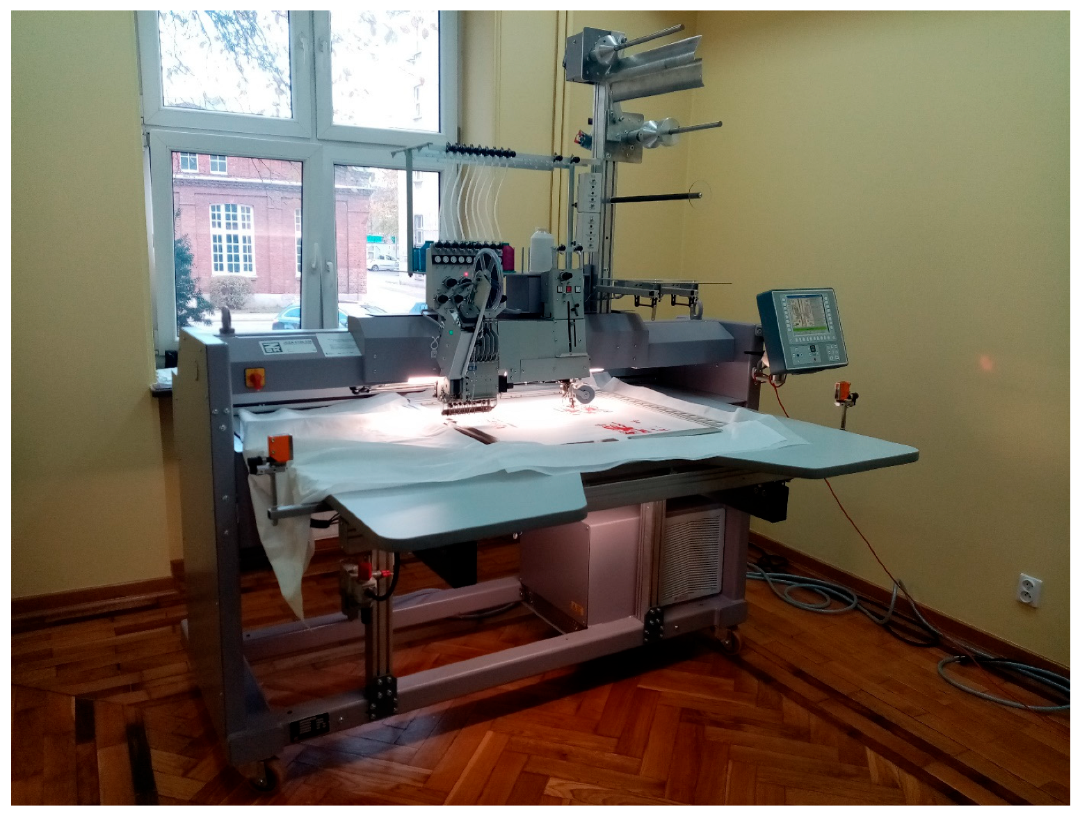
- Precision and personalization: Thanks to modern embroidery machines, it is possible to precisely arrange fibers at various angles, allowing for the creation of materials with precisely defined properties. This, in turn, enables the customization of the product to very specific customer needs.
- Lightweight and strength: Materials created on the basis of TFP combine low weight with high strength. This makes them ideal for applications in the aviation, automotive, and sports industries.
- Environmental aspects: The growing interest in environmentally friendly materials means that technical embroidery, especially when made from natural fibers, is gaining importance.
2. Materials and Methods
2.1. Material Properties
2.2. The Environmental Impact Assessment
- The matrix manufacturing, including materials, electricity consumption, and waste disposal, were excluded from the product systems boundaries as elements that were identical for both the compared scenarios. This was justified by provisions of System boundary section of ISO 14044 [21], which says that exclusion of given processes is permitted if it does not significantly change the general conclusion of the analysis.
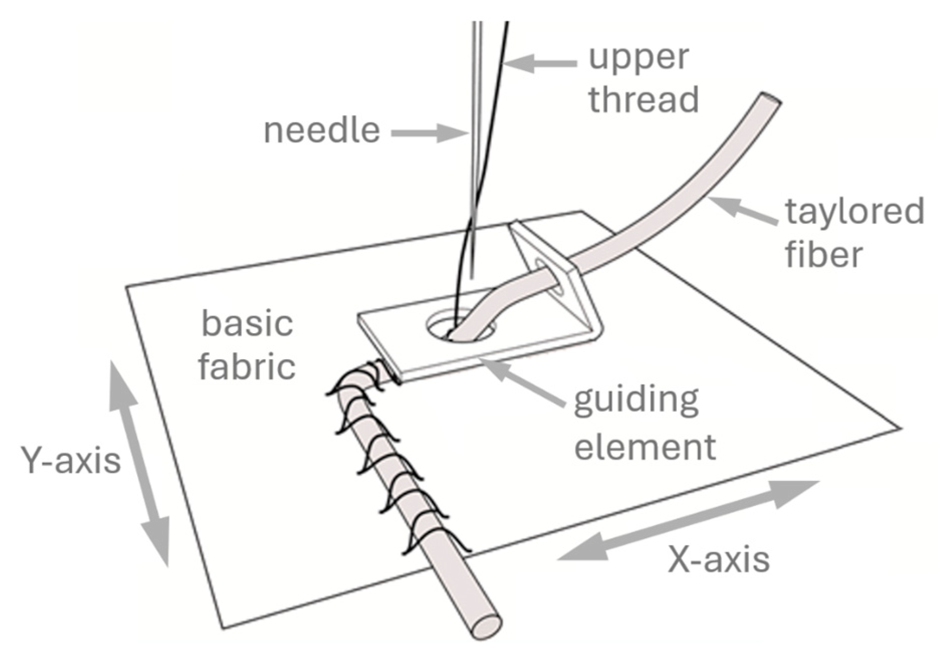
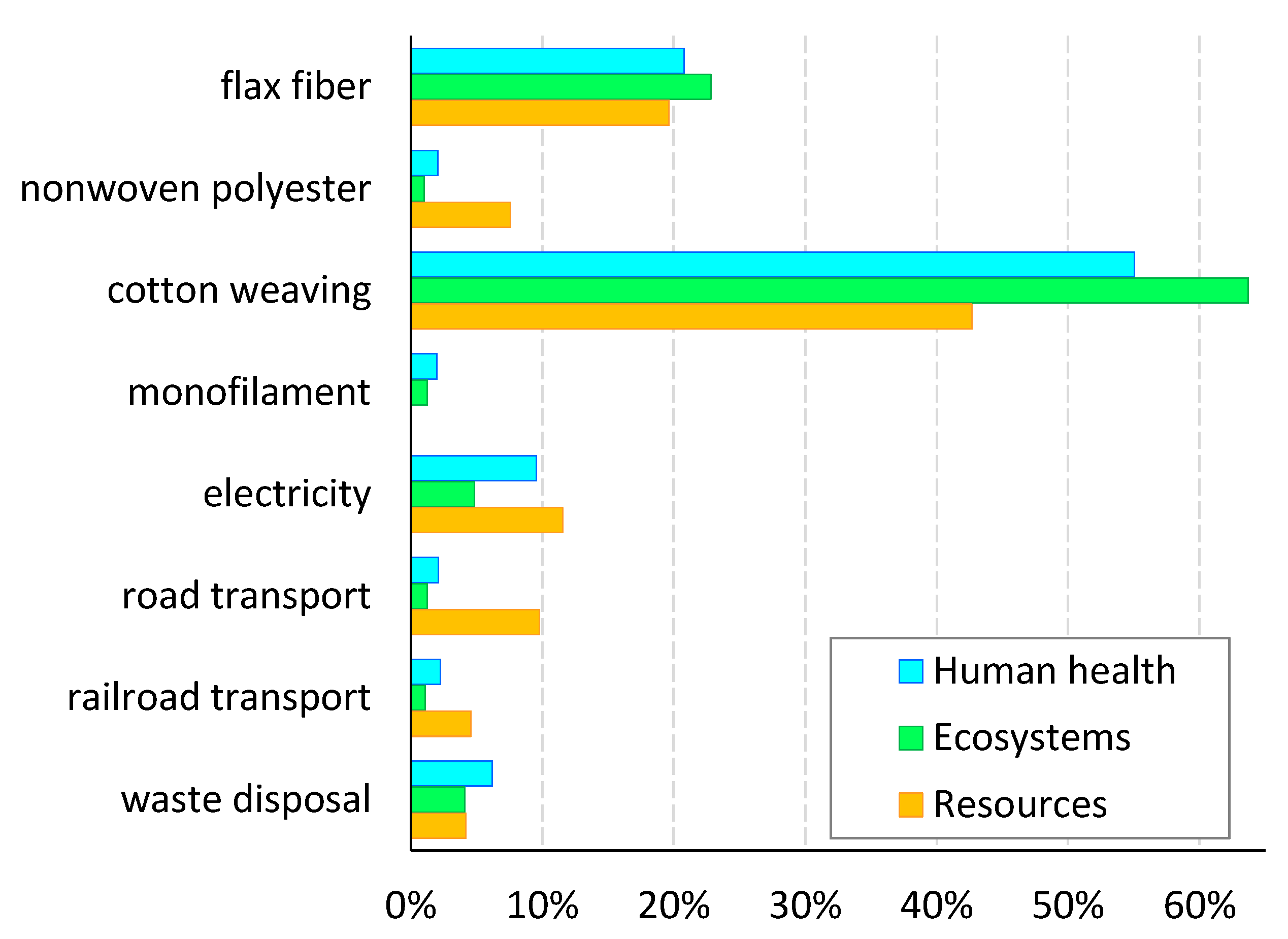
- The reinforcement based on TFP consisted of the following: nonwoven polyester with an area weight of 35 g/m2, cotton fabric with an area weight of 280 g/m2, flax roving with a linear weight of 400 tex, and polyamide monofilament with a linear weight of 11 tex.
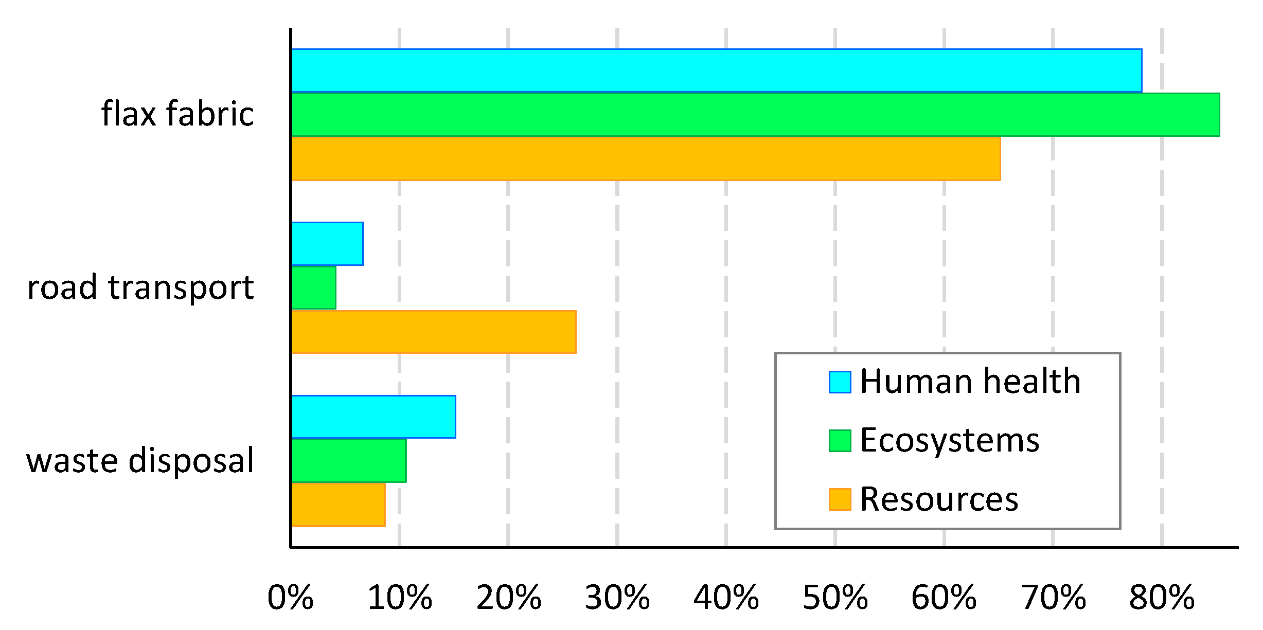
- The reinforcement based on the fabric was made from the same flax roving as used for embroidery manufacturing (400 tex), and the resulting area weight of the fabric was 400 g/m2.
- Obtaining the irregular shape of a bicycle saddle requires trimming from a rectangular piece of the fabric, which results in waste with a proportion of 0.496 m2 per 1 m2 of raw material used. In the case of TFP, the flax fibers were arranged directly into the desired shape. The waste (with the same proportion) was therefore only the nonwoven fabric and the cotton fabric on which the embroidery was made.
- The production of 1 m2 of TFP reinforcement requires the consumption of 2.052 kWh of low-voltage electricity according to the mix specific for European countries.
- As the means of transport of cotton fabric, a railroad freight was assumed with transportation distance of 12,000 km, as the estimated distance between East Asian woven cotton producer and the reinforcement manufacturing site.
- As the means of transport of flax fiber, nonwoven polyester, and polyamide monofilament, a road freight was assumed, and specifically, lorry of the size class 16–32 metric tons gross vehicle weight meeting EURO4 emission standard was operated under European conditions. The transportation distance was assumed to be 1500 km as the estimated distance between European component producers and TFP manufacturing site.
- The method of waste material disposal at the end-of-life phase was waste incineration, as one of the main current waste management strategies for most fiber-reinforced composite materials [23].
- The lifespan of compared composites was assumed to be the same.
- The allocation was based on physical (mass) principle.
3. Results and Discussion
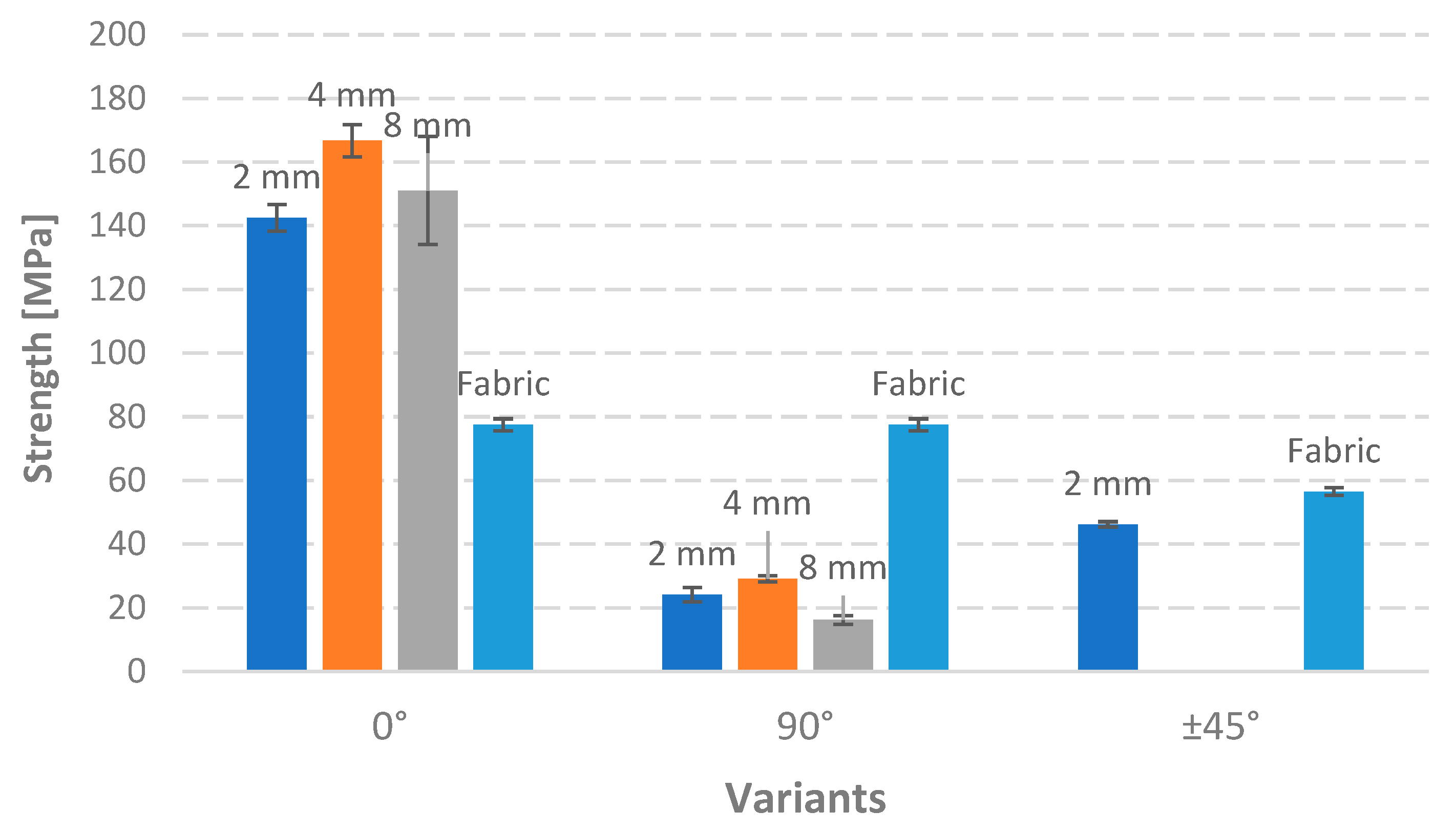
3.1. Material Properties
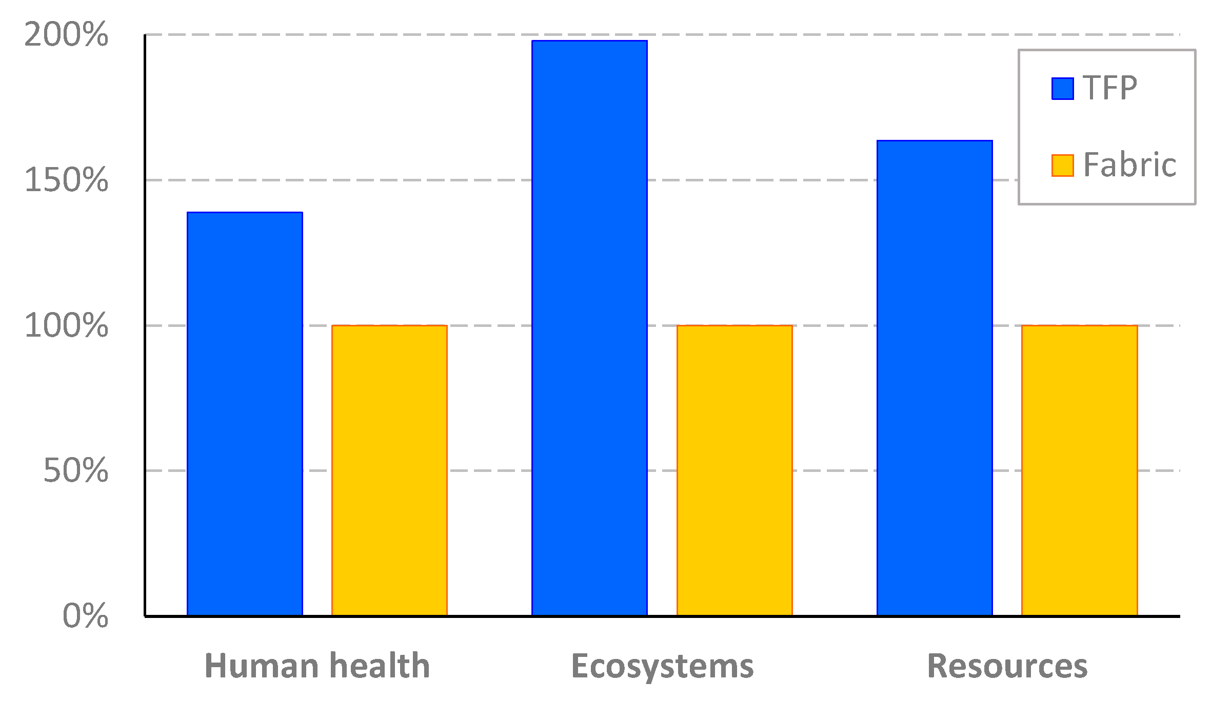
3.2. The Environmental Impact Assessment
4. Conclusions
Author Contributions
Funding
Institutional Review Board Statement
Data Availability Statement
Acknowledgments
Conflicts of Interest
References
- Ogin, S.L.; Potluri, P. Textile-reinforced composite materials. In Handbook of Technical Textiles; Elsevier: New York, NY, USA, 2016; pp. 1–26. [Google Scholar]
- Kim, J.K.; Sham, M.L. Impact and delamination failure of woven-fabric composites. Compos. Sci. Technol. 2000, 60, 745–761. [Google Scholar] [CrossRef]
- Spickenheuer, A.; Schulz, M.; Gliesche, K.; Heinrich, G. Using tailored fibre placement technology for stress adapted design of composite structures. Plast. Rubber Compos. 2008, 37, 227–232. [Google Scholar] [CrossRef]
- Wright, T.; Bechtold, T.; Bernhard, A.; Manian, A.P.; Scheiderbauer, M. Tailored fibre placement of carbon fibre rovings for reinforced polypropylene composite part 1: PP infusion of carbon reinforcement. Compos. Part B Eng. 2019, 162, 703–711. [Google Scholar] [CrossRef]
- Radavičiene, S.; Juciene, M.; Juchnevičiene, Z.; Čepukone, L.; Viļumsone, A.; Briedis, U.; Baltiņa, I. Analysis of Shape Nonconformity between Embroidered Element. Mater. Sci. 2014, 20, 84–89. [Google Scholar]
- Bittrich, L.; Spickenheuer, A.; Humberto, J.; Almeida, S.; Müller, S.; Kroll, L.; Heinrich, G. Optimizing Variable-Axial Fiber-Reinforced Composite Laminates: The Direct Fiber Path Optimization Concept. Math. Probl. Eng. 2019, 2019, 8260563. [Google Scholar] [CrossRef]
- Poniecka, A.; Barburski, M.; Ranz, D.; Cuartero, J.; Miralbes, R. New solutions in the production of composites—Mechanical properties of composites reinforced with technical embroidery and woven fabric made of flax fibers. Vlak. A Textilthis 2023, 30, 49–53. [Google Scholar] [CrossRef]
- Poniecka, A.; Barburski, M.; Urbaniak, M. Mechanical properties of composites reinforced with technical embroidery made of flax fibers. AUTEX Res. J. 2022, 22, 438–445. [Google Scholar] [CrossRef]
- Gliesche, K.; Hübner, T.; Orawetz, H. Application of the tailored fibre placement (TFP) process for a local reinforcement on an “open-hole” tension plate from carbon/epoxy laminates. Compos. Sci. Technol. 2003, 63, 81–88. [Google Scholar] [CrossRef]
- Uhlig, K.; Spickenheuer, A.; Gliesche, K.; Karb, I. Strength of CFRP open hole laminates made from NCF, TFP and braided preforms under cyclic tensile loading. Plast. Rubber Compos. 2010, 39, 247–255. [Google Scholar] [CrossRef]
- Costalonga Martins, V.; Cutajar, S.; van der Hoven, C.; Baszyński, P.; Dahy, H. FlexFlax Stool: Validation of Moldless Fabrication of Complex Spatial Forms of Natural Fiber-Reinforced Polymer (NFRP) Structures through an Integrative Approach of Tailored Fiber Placement and Coreless Filament Winding Techniques. Appl. Sci. 2020, 10, 3278. [Google Scholar] [CrossRef]
- Hassan, A.; Dahy, H. Continuous natural fiber-reinforced shape memory polymer biocomposites: Design and fabrication for sustainable self-folding architectural applications. Smart Mater. Struct. 2025, 34, 015051. [Google Scholar] [CrossRef]
- Saslawsky, K.; Steixner, C.; Tucker, M.; Costalonga, V.; Dahy, H. FlaxPack: Tailored Natural Fiber Reinforced (NFRP) Compliant Folding Corrugation for Reversibly Deployable Bending-Active Curved Structures. Polymers 2024, 16, 515. [Google Scholar] [CrossRef] [PubMed]
- Cáceres, G.d.A.; Lisbôa, T.d.V.; Elschner, C.; Spickenheuer, A. Experimental GlobalWarming Potential-Weighted Specific Stiffness Comparison among Different Natural and Synthetic Fibers in a Composite Component Manufactured by Tailored Fiber Placement. Polymers 2024, 16, 726. [Google Scholar] [CrossRef] [PubMed]
- Mecnika, V.; Hoerr, M.; Krievins, I.; Jockenhoevel, S.; Gries, T. Technical Embroidery for Smart Textiles: Review. Mater. Sci. Text. Cloth. Technol. 2014, 9, 56–63. [Google Scholar] [CrossRef]
- SR GREENPOXY 33. Available online: https://sicomin.com/en/epoxy-products/epoxy/contact-vacuum-lamination/sr-greenpoxy-33 (accessed on 16 May 2025).
- Flax Reinforcements for Composites. Available online: https://www.safilin.fr/composites/?lang=en (accessed on 16 May 2025).
- ISO 527-4:2023; Plastics—Determination of Tensile Properties Part 4: Test Conditions for Isotropic and Orthotropic Fibre-Reinforced Plastic Composites. International Organization for Standardization: Geneva, Switzerland, 2023.
- Poniecka, A.; Barburski, M.; Ranz, D.; Cuartero, J.; Miralbes, R. Comparison of Mechanical Properties of Composites Reinforced with Technical Embroidery, UD and Woven Fabric Made of Flax Fibers. Materials 2022, 15, 7469. [Google Scholar] [CrossRef] [PubMed]
- ISO 14040; Environmental Management—Life Cycle Assessment—Principles and Framework. International Organization for Standardization: Geneva, Switzerland, 2006.
- ISO 14044; Environmental Management—Life Cycle Assessment—Requirements and Guidelines. International Organization for Standardization: Geneva, Switzerland, 2006.
- Wernet, G.; Bauer, C.; Steubing, B.; Reinhard, J.; Moreno-Ruiz, E.; Weidema, B. The ecoinvent database version 3 (part I): Overview and methodology. Int. J. Life Cycle Assess. 2016, 21, 1218–1230. [Google Scholar] [CrossRef]
- Yuan, M.; Li, Z.; Teng, Z. Progress and prospects of recycling technology for carbon fiber reinforced polymer. Front. Mater. 2024, 11, 1484544. [Google Scholar] [CrossRef]
- Huijbregts, M.A.J.; Steinmann, Z.J.N.; Elshout, P.M.F.; Stam, G.; Verones, F.; Vieira, M.; Zijp, M.; Hollander, A.; van Zelm, R. ReCiPe2016: A harmonised life cycle impact assessment method at midpoint and endpoint level. Int. J. Life Cycle Assess. 2017, 22, 138–147. [Google Scholar] [CrossRef]
- Huijbregts, M.A.J.; Steinmann, Z.J.N.; Elshout, P.M.F.; Stam, G.; Verones, F.; Vieira, M.; Hollander, A.; Zijp, M.; van Zelm, R. ReCiPe 2016. A Harmonized Life Cycle Impact Assessment Method at Midpoint and Endpoint Level. Report I: Characterization; National Institute for Public Health and the Environment: Bilthoven, The Netherlands, 2016. [Google Scholar]
- Radhouane, M.; Chokri, B.; Jamel, B. Reduction and thermodynamic treatment of NOx emissions in a spark ignition engine using isooctane and an oxygenated fuel (ethanol). Int. J. Low-Carbon Technol. 2023, 18, 1258–1266. [Google Scholar] [CrossRef]


| Variant | Name | Graphic Orientation of Roving in Each Layer | Area Mass of Dry Sample [g/m2] | Area Mass of Composite [g/m2] | Volume Fraction [%] |
|---|---|---|---|---|---|
| Embroidery 0° 2 mm | 0° 2 mm | ││││ | 1424 | 3439 | 41 |
| Embroidery 0° 4 mm | 0° 4 mm | ││││ | 1273 | 3318 | 38 |
| Embroidery 0° 8 mm | 0° 8 mm | ││││ | 1227 | 3561 | 34 |
| Embroidery ±45° 2 mm | ±45° 2 mm |  | 1387 | 3425 | 40 |
| Embroidery 90° 2 mm | 90° 2 mm | ─ ─ ─ ─ | 1515 | 5015 | 30 |
| Embroidery 90° 4 mm | 90° 4 mm | ─ ─ ─ ─ | 1303 | 3455 | 38 |
| Embroidery 90° 8 mm | 90° 8 mm | ─ ─ ─ ─ | 1227 | 3561 | 34 |
| Woven fabric 0°/90° | Fabric 0°/90° |  | 1802 | 4309 | 42 |
| Woven fabric ±45° | Fabric ±45° |  | 1867 | 4254 | 44 |
| Component | TFP | Fabric |
|---|---|---|
| Flax fibers | 886 g/m2 | |
| Cotton fabric | 280 g/m2 | |
| Nonwoven polyester | 35 g/m2 | |
| Polyamide monofilament | 26.7 g/m2 | |
| Flax fabric | 1600 g/m2 | |
| Low-voltage electricity consumption | 2.052 kWh/m2 | |
| Railroad transport | 3.36 t·km | |
| Transport by lorry 16–32 t | 1.422 t·km | 2.40 t·km |
| Waste textile material | 1227.7 g/m2 | 1600 g/m2 |
| Impact Category | Unit | TFP | Fabric |
|---|---|---|---|
| Fine particulate matter formation | kg PM2.5 eq | 0.0147 | 0.0082 |
| Fossil resource scarcity | kg oil eq | 1.369 | 0.577 |
| Freshwater ecotoxicity | kg 1,4-DCB | 0.394 | 0.067 |
| Freshwater eutrophication | kg P eq | 3.39 × 10⁻³ | 6.79 × 10⁻⁴ |
| Global warming | kg CO2 eq | 7.475 | 3.937 |
| Human carcinogenic toxicity | kg 1,4-DCB | 0.307 | 0.056 |
| Human non-carcinogenic toxicity | kg 1,4-DCB | 4.172 | −3.837 |
| Ionizing radiation | kBq Co-60 eq | 0.682 | 0.0036 |
| Land use | m2a crop eq | 2.697 | 0.573 |
| Marine ecotoxicity | kg 1,4-DCB | 0.423 | 0.070 |
| Marine eutrophication | kg N eq | 0.0198 | 0.0082 |
| Mineral resource scarcity | kg Cu eq | 0.0180 | 0.0061 |
| Ozone formation, human health | kg NOx eq | 0.0258 | 0.0170 |
| Ozone formation, terrestrial ecosystems | kg NOx eq | 0.0262 | 0.0172 |
| Stratospheric ozone depletion | kg CFC11 eq | 4.84 × 10⁻⁵ | 4.11 × 10⁻⁵ |
| Terrestrial acidification | kg SO2 eq | 0.0536 | 0.0363 |
| Terrestrial ecotoxicity | kg 1,4-DCB | 20.170 | 2.060 |
| Water consumption | m3 | 2.017 | 0.799 |
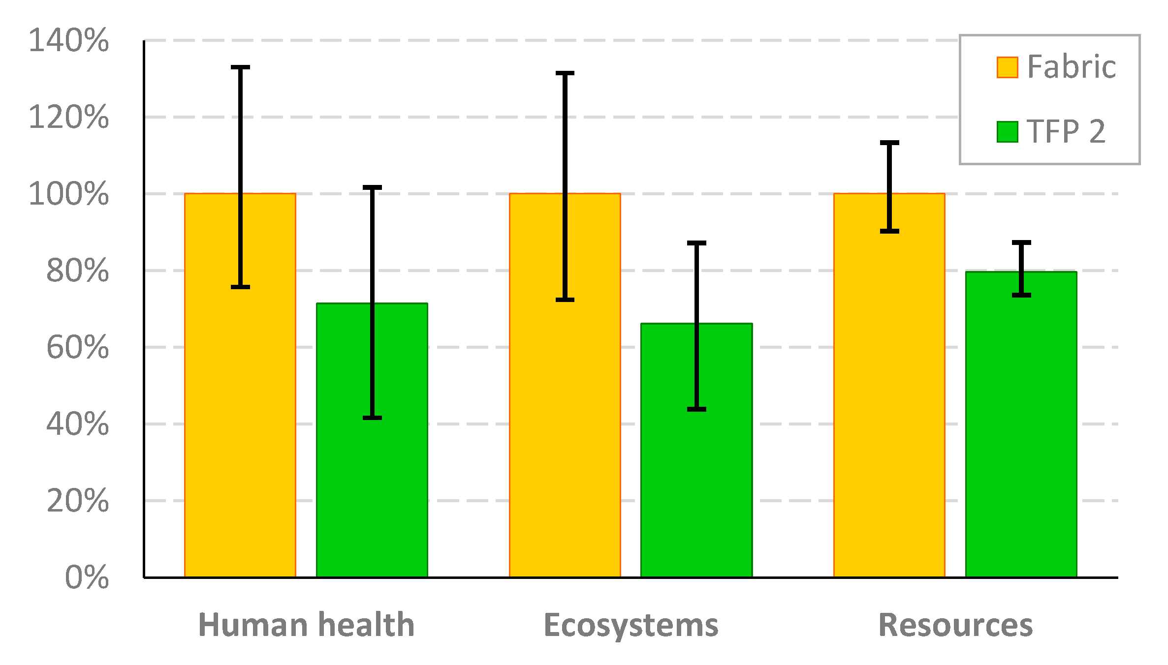
| Endpoint | TFP2 Scenario | |||
|---|---|---|---|---|
| Mean | SD | 5% | 95% | |
| Human health | 7.1 × 10⁻⁶ | 1.23 × 10⁻⁶ | 4.14 × 10⁻⁶ | 1.0 × 10⁻⁵ |
| Ecosystems | 2.4 × 10⁻⁸ | 3.26 × 10⁻⁹ | 1.62 × 10⁻⁸ | 3.2 × 10⁻⁸ |
| Resources | 1.4 × 10⁻¹ | 8.01 × 10⁻³ | 1.28 × 10⁻¹ | 1.5 × 10⁻¹ |
| Endpoint | Fabric scenario | |||
| Mean | SD | 5% | 95% | |
| Human health | 9.9 × 10⁻⁶ | 1.21 × 10⁻⁶ | 7.54 × 10⁻⁶ | 1.3 × 10⁻⁵ |
| Ecosystems | 3.7 × 10⁻⁸ | 4.55 × 10⁻⁹ | 2.67 × 10⁻⁸ | 4.9 × 10⁻⁸ |
| Resources | 1.7 × 10⁻¹ | 1.29 × 10⁻² | 1.58 × 10⁻¹ | 2.0 × 10⁻¹ |
Disclaimer/Publisher’s Note: The statements, opinions and data contained in all publications are solely those of the individual author(s) and contributor(s) and not of MDPI and/or the editor(s). MDPI and/or the editor(s) disclaim responsibility for any injury to people or property resulting from any ideas, methods, instructions or products referred to in the content. |
© 2025 by the authors. Licensee MDPI, Basel, Switzerland. This article is an open access article distributed under the terms and conditions of the Creative Commons Attribution (CC BY) license (https://creativecommons.org/licenses/by/4.0/).
Share and Cite
Marcinkowski, A.; Poniecka, A.; Barburski, M. Life Cycle Assessment of Flax Fiber Technical Embroidery-Reinforced Composite. Polymers 2025, 17, 1888. https://doi.org/10.3390/polym17131888
Marcinkowski A, Poniecka A, Barburski M. Life Cycle Assessment of Flax Fiber Technical Embroidery-Reinforced Composite. Polymers. 2025; 17(13):1888. https://doi.org/10.3390/polym17131888
Chicago/Turabian StyleMarcinkowski, Andrzej, Agata Poniecka, and Marcin Barburski. 2025. "Life Cycle Assessment of Flax Fiber Technical Embroidery-Reinforced Composite" Polymers 17, no. 13: 1888. https://doi.org/10.3390/polym17131888
APA StyleMarcinkowski, A., Poniecka, A., & Barburski, M. (2025). Life Cycle Assessment of Flax Fiber Technical Embroidery-Reinforced Composite. Polymers, 17(13), 1888. https://doi.org/10.3390/polym17131888