4.1.1. Girder-End Displacement
To ensure the validity of the finite element model, a multi-level verification approach was adopted. First, the main cable profile under dead load was compared with the theoretical catenary solution, showing good agreement. Second, the modeling methods and parameters for the restraining devices were selected based on established references, software guidelines, and relevant design codes to ensure accuracy and engineering reliability. As a critical control parameter in long-span suspension bridges, the longitudinal displacement at the girder ends directly affects the design of expansion joints and the selection of bearing systems [
2,
4].
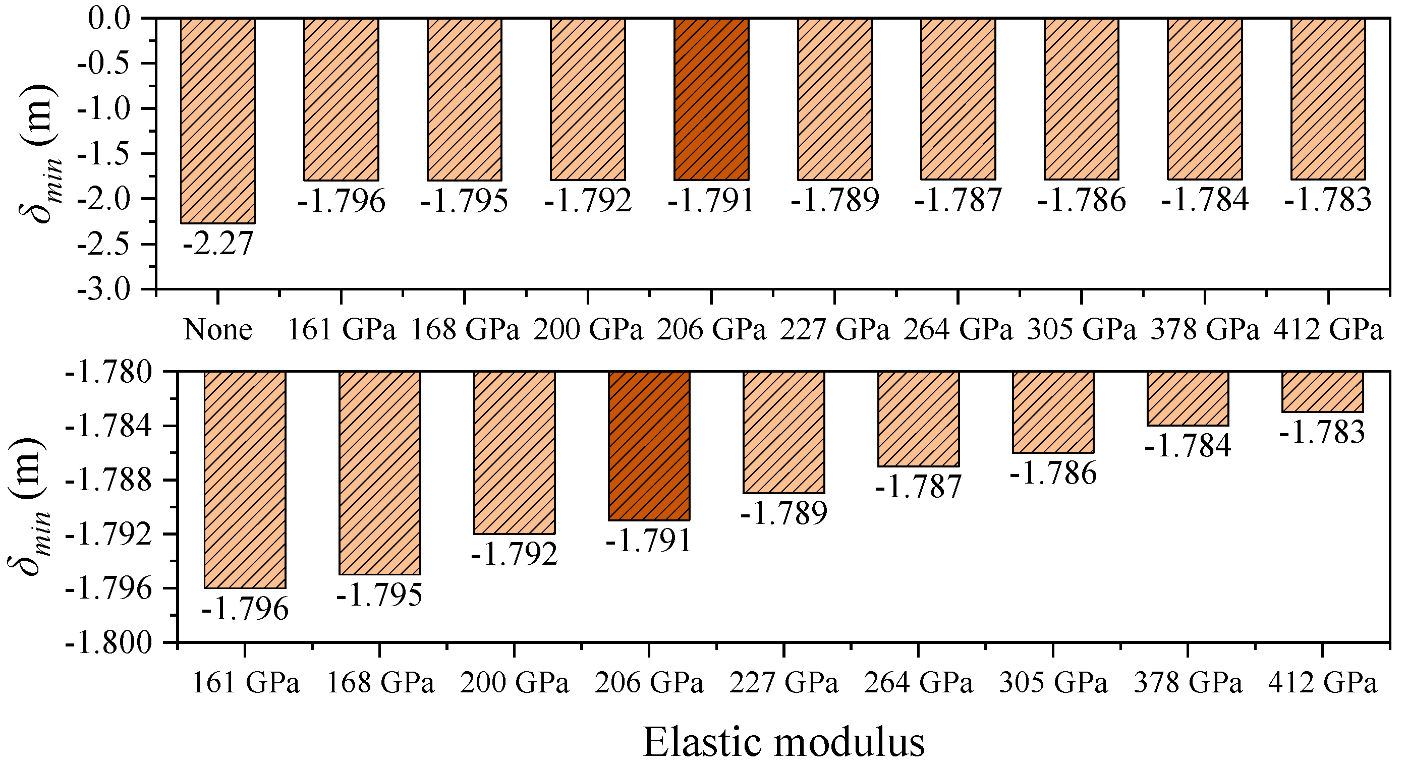
Figure 8 and
Figure 9 illustrate the influence of central buckle stiffness on the longitudinal displacement of the main girder. The results for the steel cable central buckle are highlighted in darker shades. To better emphasize the effects of different CFRP cable stiffnesses on structural performance, the figures have been zoomed in and the baseline case (without a central buckle) has been omitted. Under the baseline condition, the end displacement of the girder exhibits a pronounced bidirectional asymmetry: the maximum positive displacement
δmax is 2.249 m, and the maximum negative displacement
δmin is –2.270 m. The displacement amplitude difference between the cable and the girder,
δcable −
δgirder, is 0.021 m (
Table 2), which confirms the geometric nonlinearity associated with large displacement responses in long-span suspension bridges.
After the introduction of CFRP central buckles, the structural response is significantly improved. For instance, using CFRP with an elastic modulus of 161 GPa, the maximum end displacement of the girder is reduced to 1.716 m, representing a 23.7% decrease compared to the no-buckle case. This clearly demonstrates the effectiveness of the central buckle in limiting longitudinal displacement. Further analysis reveals a nonlinear relationship between displacement suppression efficiency and material stiffness. When the elastic modulus increases from 161 GPa to 412 GPa (a 156% increase), the maximum displacement is only slightly reduced from 1.716 m to 1.702 m—a reduction of merely 0.8%. This indicates that there exists a stiffness optimization threshold for the central buckle system, beyond which further increases in material stiffness yield diminishing returns in structural control effectiveness.
In addition, the CFRP cable with an elastic modulus of 161 GPa exhibits highly consistent displacement control performance compared to traditional steel cables, with a maximum displacement difference of only 0.005 m. This confirms the feasibility of using CFRP as a stiffness-equivalent substitute for steel. Given that CFRP has only 20% of the density of steel, its lightweight nature offers significant advantages in reducing structural self-weight, simplifying construction, and enhancing seismic performance.
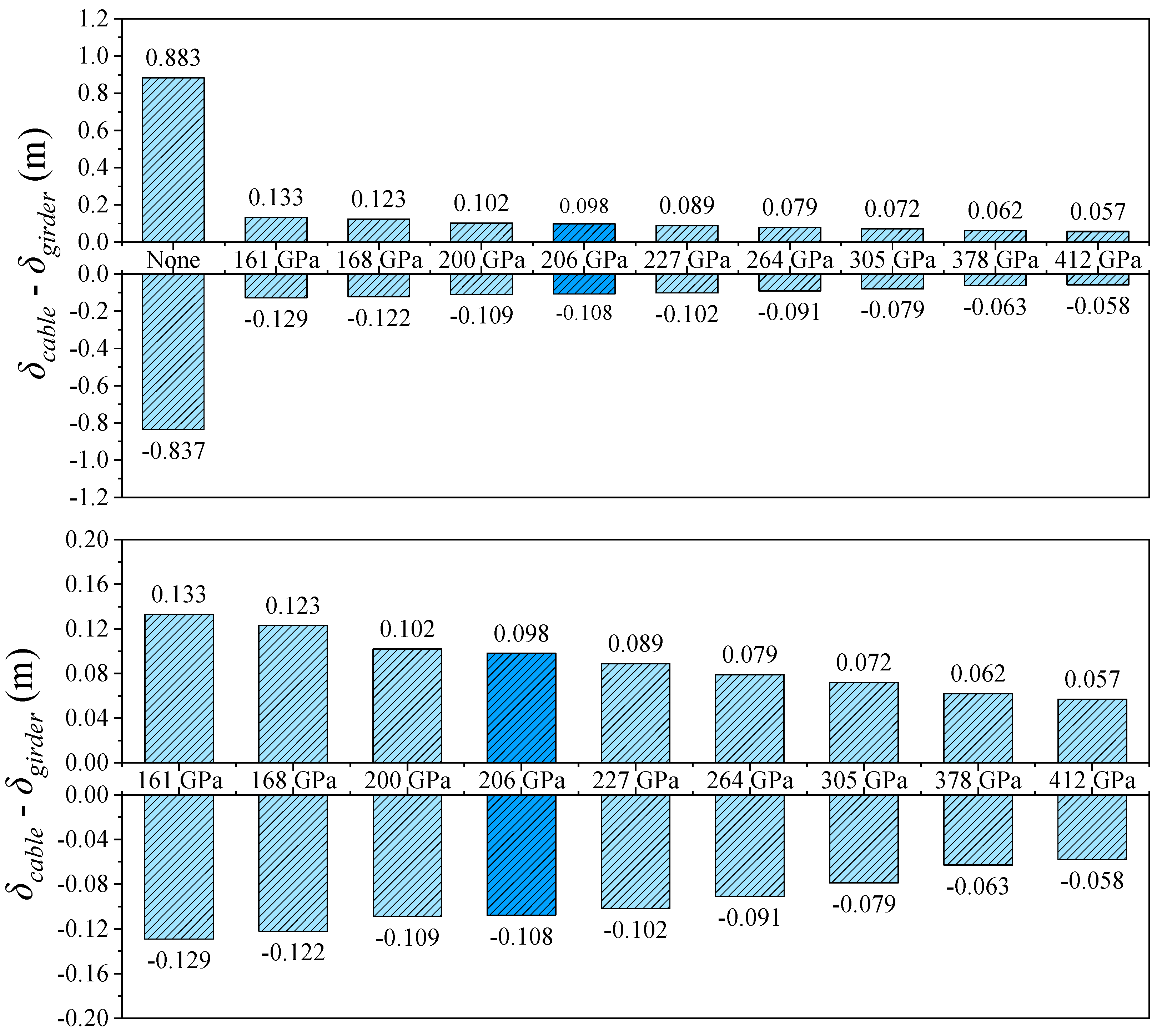
The relative displacement between the cable and girder at midspan shows an even more pronounced trend than the girder-end displacement. As shown in
Figure 5 and
Figure 10, in the absence of a central buckle, the relative displacement between the cable and girder reaches ±1.028 m. After introducing a CFRP central buckle with an elastic modulus of 161 GPa, this value significantly drops to +0.023 m and –0.036 m, representing an overall reduction of 97.8%. This result indicates that even low-stiffness FRP materials can effectively coordinate and constrain the deformation between cable and girder, demonstrating the high efficiency of the central buckle in suppressing relative displacement. Consistent with the conclusions drawn from longitudinal girder displacement control, the relative displacement suppression continues to improve with increasing CFRP stiffness but the rate of improvement diminishes progressively. This nonlinear relationship provides a critical basis for optimizing the material selection and stiffness configuration of the central buckle from both engineering and economic perspectives, avoiding resource waste and potential negative effects associated with over-stiffening.
Moreover, under all conditions, the maximum transverse displacement at the midspan of the main girder, δG, max, remains stable, fluctuating within only 0.013 m (ranging from 12.668 m to 12.681 m). This indicates that variations in central buckle stiffness have negligible influence on transverse displacement, which is primarily governed by the torsional stiffness of the girder itself. Therefore, the design of the central buckle should focus on longitudinal control performance, while transverse displacement is largely dependent on the girder’s overall torsional capacity.
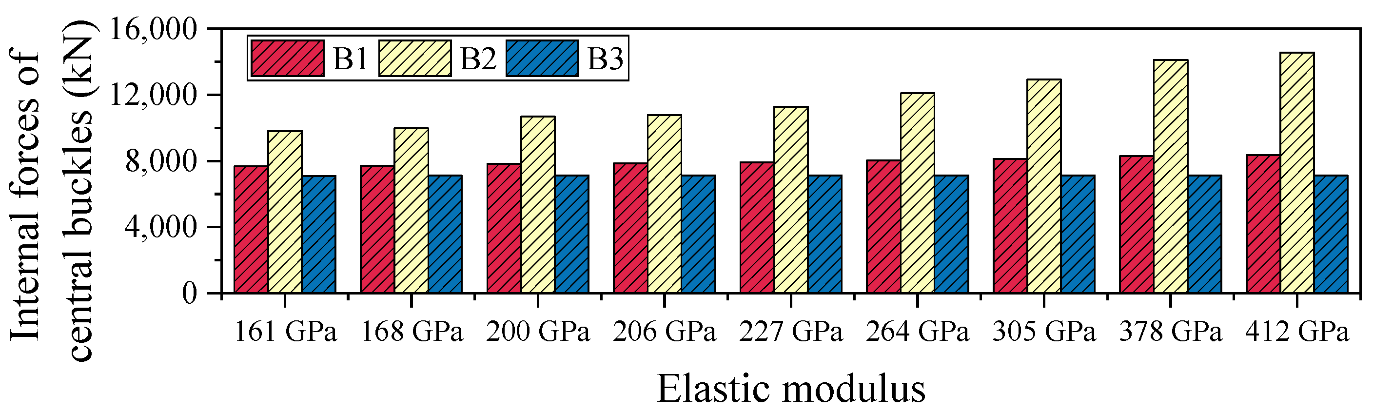
4.1.2. Internal Forces of Central Buckles
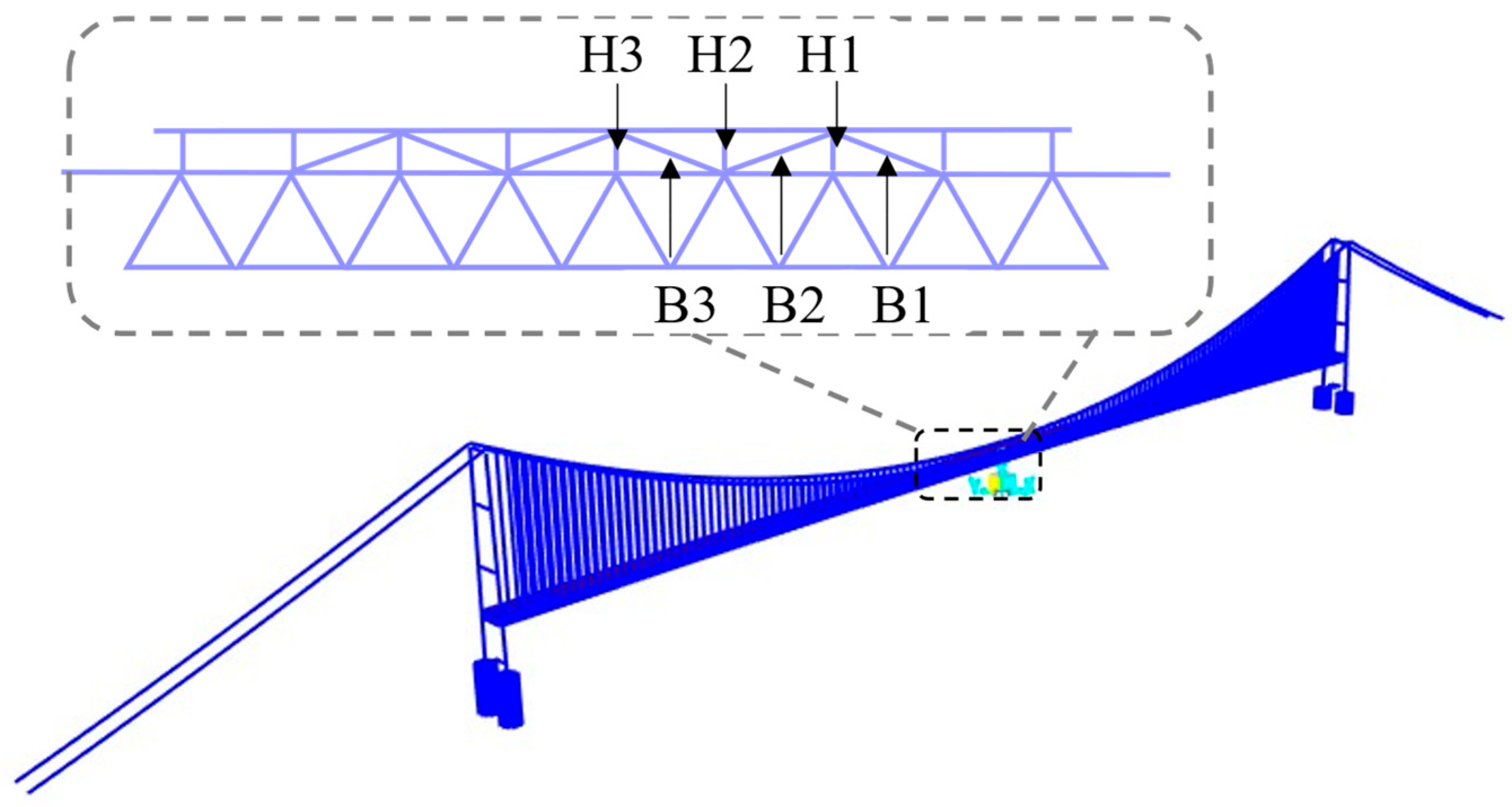
Table 3 and
Figure 11 present the axial force distribution of the three side members of the central buckle under the 161 GPa elastic modulus condition. The internal forces in B1, B2, and B3 are 7674 kN, 9810 kN, and 7100 kN, respectively. As the FRP material’s elastic modulus increases from 161 GPa to 412 GPa, the axial forces in all three members exhibit nonlinear growth but the magnitude of increase varies significantly, revealing the spatial non-uniformity of internal force redistribution. Specifically, the force in B1 increases from 7674 kN to 8350 kN (an 8.8% increase), while B2 sees a substantial rise from 9810 kN to 14,323 kN (a 46.0% increase), and B3 experiences only a marginal increase to 7163 kN (a 0.9% increase). Among the three, B2 shows the highest sensitivity to changes in elastic modulus, indicating it serves as the primary load-bearing path. In contrast, the internal force responses of B1 and B3 are more influenced by local deformation compatibility mechanisms, making them less sensitive to stiffness variations.
Overall, the maximum internal force increase in the central buckle (B2) reaches 46%, demonstrating the significant amplifying effect of material stiffness on internal force levels. However, in terms of displacement control, the improvement achieved by the high-modulus CFRP (412 GPa) over the low-modulus CFRP (161 GPa) is less than 1.2%. This indicates that the sensitivity of internal forces to stiffness enhancement is much greater than the marginal benefit in displacement control. Unless special performance requirements are present, excessively increasing the stiffness of the central buckle may significantly raise internal force levels, potentially leading to stricter demands on fatigue resistance and joint detailing. Considering both control effectiveness and structural safety, it is recommended to adopt CFRP cables with a relatively lower elastic modulus as the design choice for central buckle components.
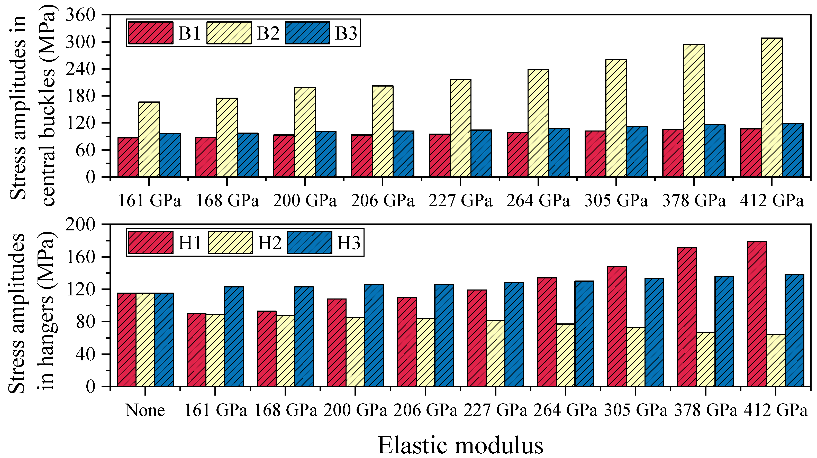
4.1.3. Stress Amplitudes in Central Buckles and Hangers
Table 4 summarizes the stress amplitude responses of the central buckle and hangers under vehicular live load conditions for various elastic moduli. In suspension bridges, a typical negative correlation is observed between the stiffness of the flexible central buckle and the stress amplitude of hangers: as the stiffness of the central buckle increases, its ability to share live load improves, leading to a significant increase in its own stress amplitude while simultaneously helping to reduce the stress amplitude in adjacent hangers. Conversely, a central buckle with lower stiffness—though more deformable and experiencing smaller stress amplitudes itself—tends to transfer more load to the hangers, thereby increasing their stress amplitudes.
As shown in
Figure 12, in the absence of a central buckle, the stress amplitude in all monitored hangers is 115 MPa, indicating a relatively uniform stress distribution when longitudinal restraint is lacking. After introducing a CFRP central buckle with an elastic modulus of 161 GPa, the stress distribution becomes markedly redistributed: the stress amplitudes at monitoring points 1 and 2 drop to 90 MPa and 89 MPa, respectively, representing reductions of 21.7% and 22.6%; however, the stress at point 3 rises to 123 MPa, an increase of 7.0%, indicating a differentiated influence of the central buckle on the force distribution among different hangers. When the CFRP elastic modulus is further increased to 412 GPa, the stress at point 1 significantly increases to 179 MPa, while that at point 2 decreases to 64 MPa, reflecting a more pronounced stress concentration effect resulting from the increased stiffness.


