
Automated Cold Embossing for the Integration of Optical Lenses onto the Surface of Acrylonitrile Butadiene Styrene (ABS) 3D-Printed Parts


Abstract
1. Introduction
2. Experimental Materials and Methods
2.1. Test Part
2.1.1. Emboss Part Design and 3D Printing
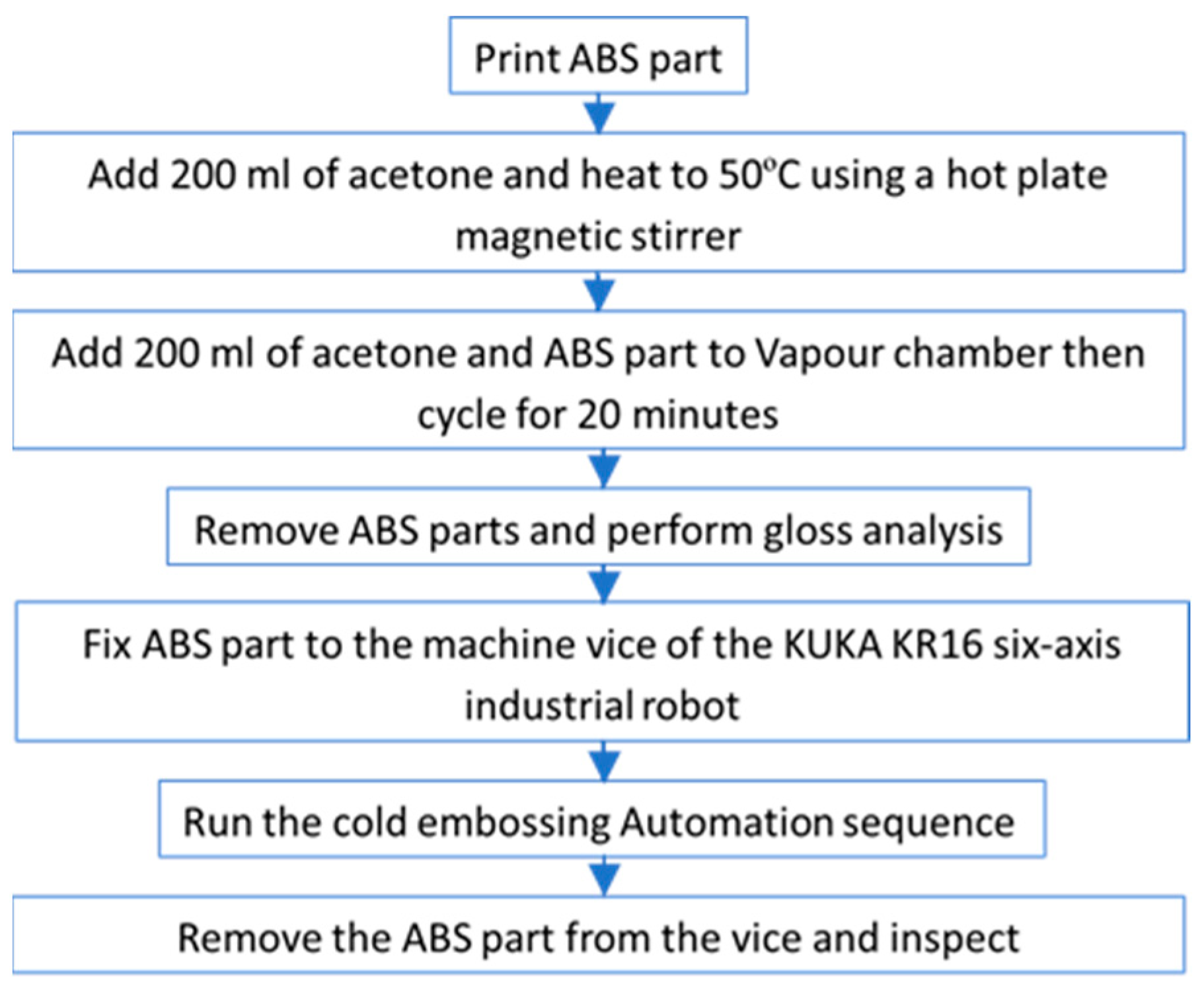
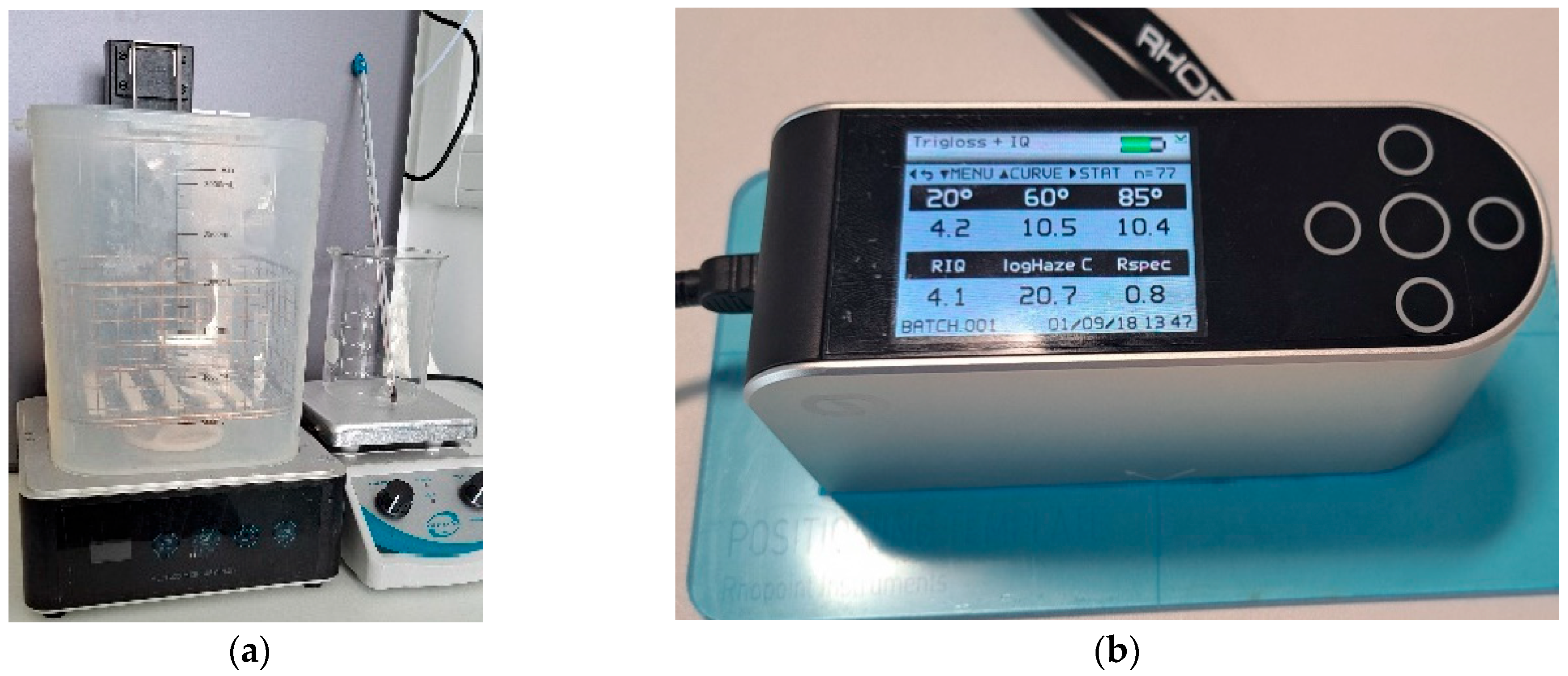
2.1.2. Vapour Chamber
2.1.3. Gloss Analysis
2.2. Embossing Stamper
2.2.1. Fresnel Lens Stamper
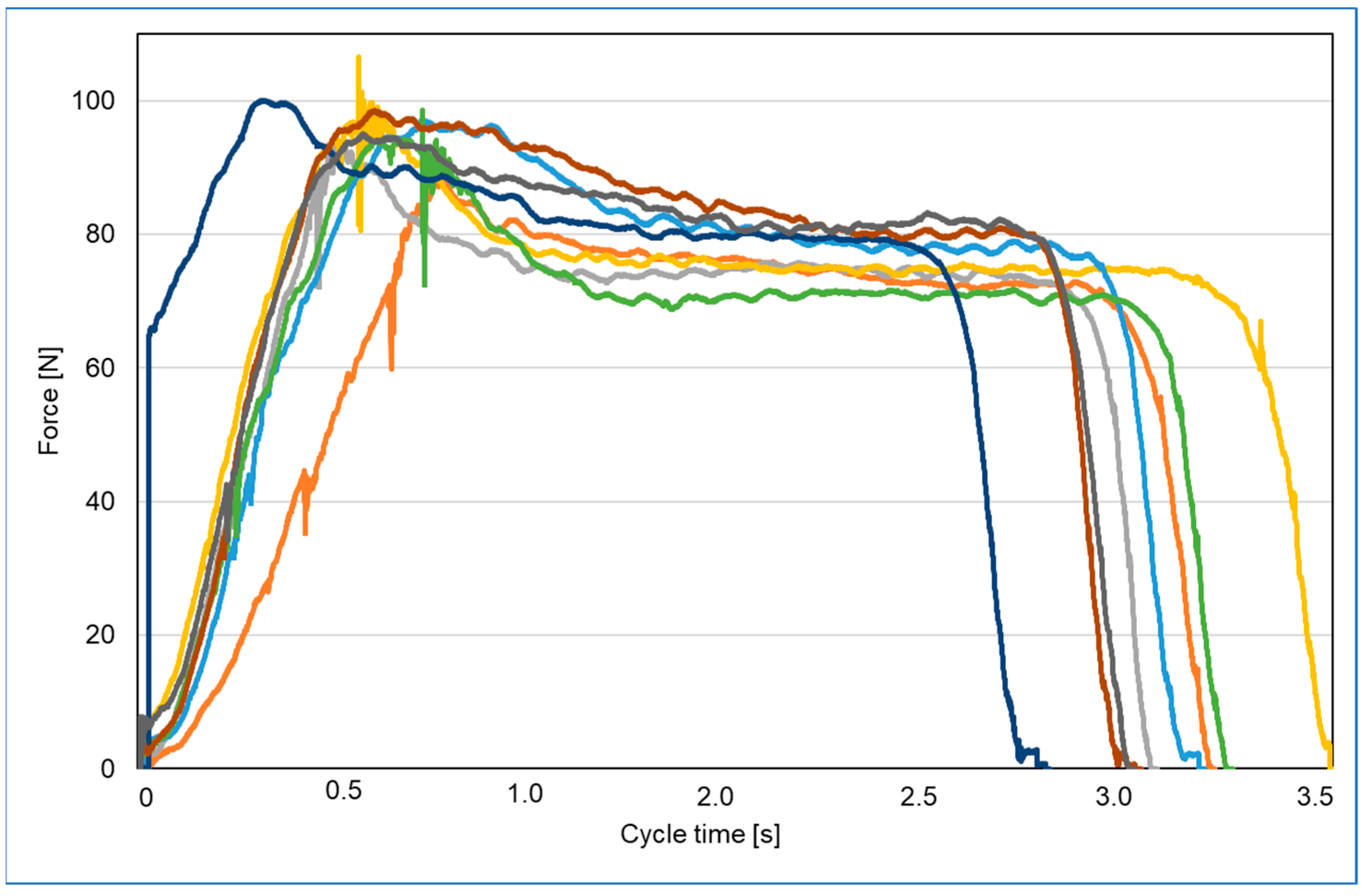
2.2.2. Stamper Force Test
2.3. Automation
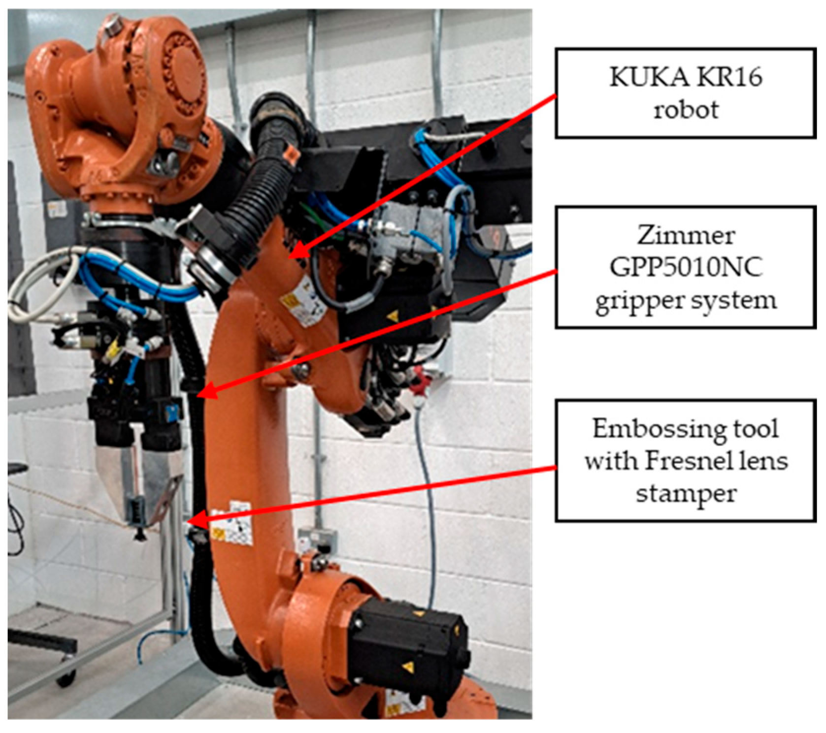
2.3.1. KUKA Robot
2.3.2. Sequence
3. Results
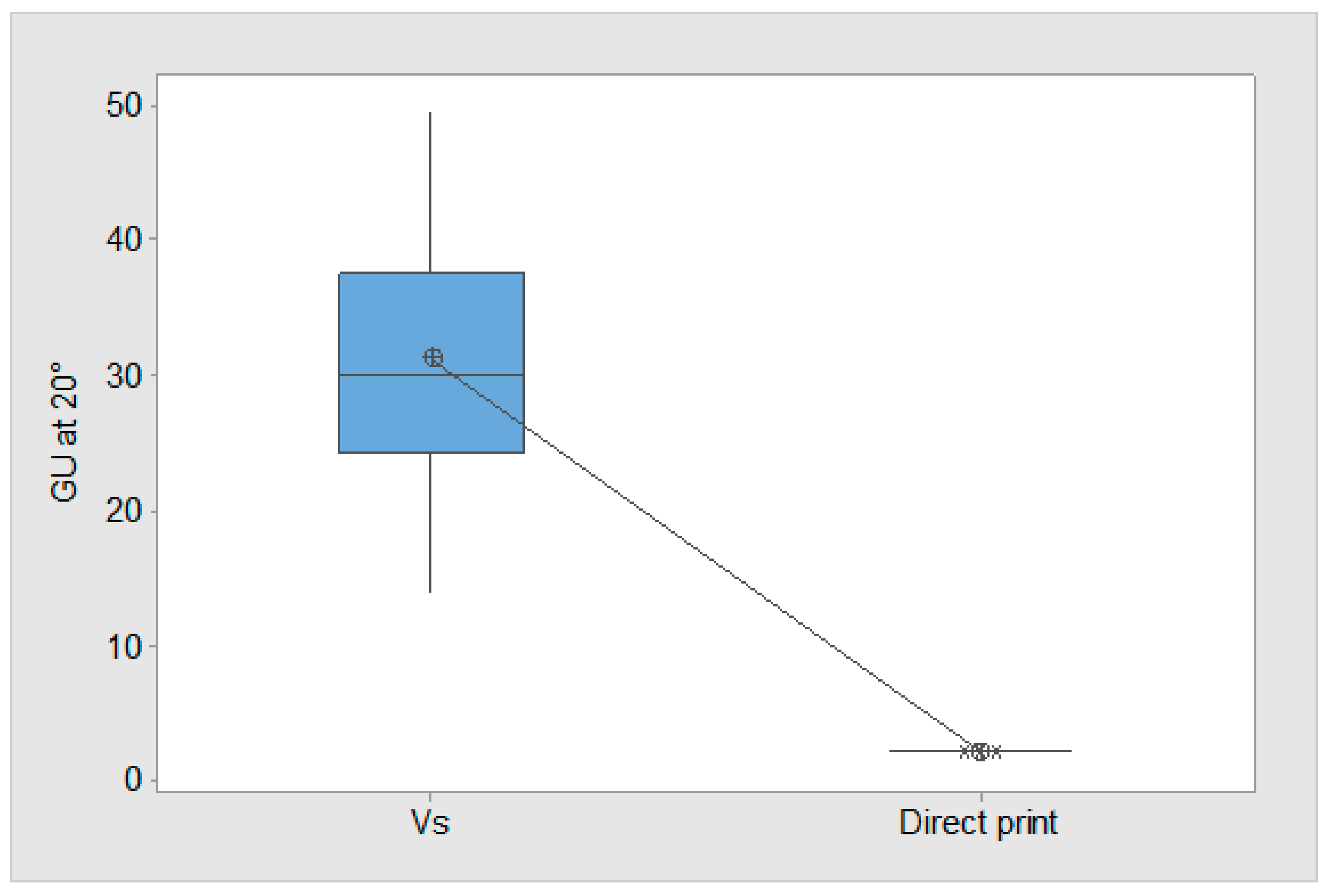
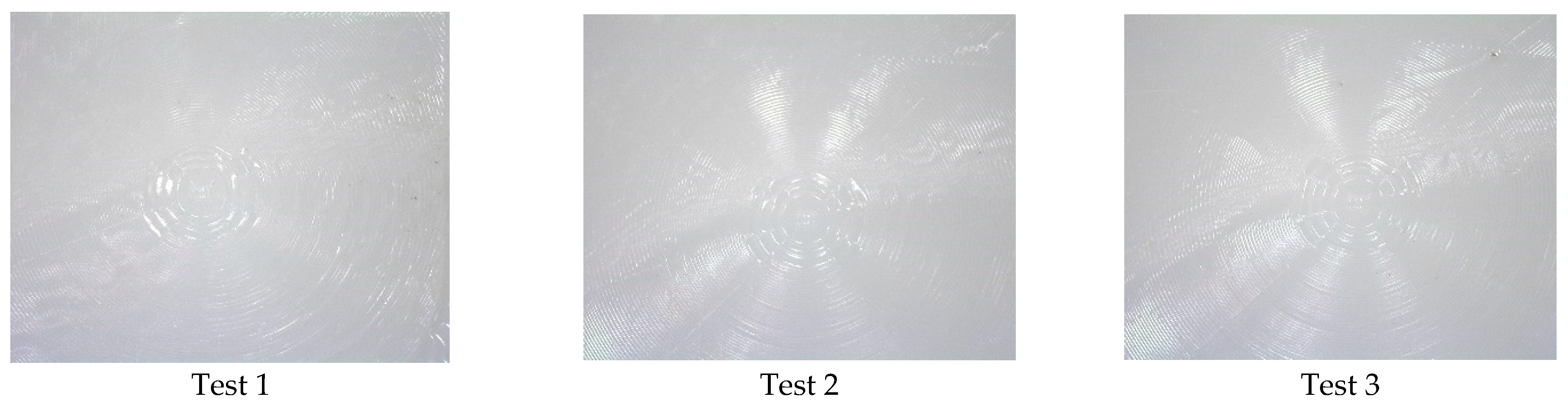
3.1. Gloss Results
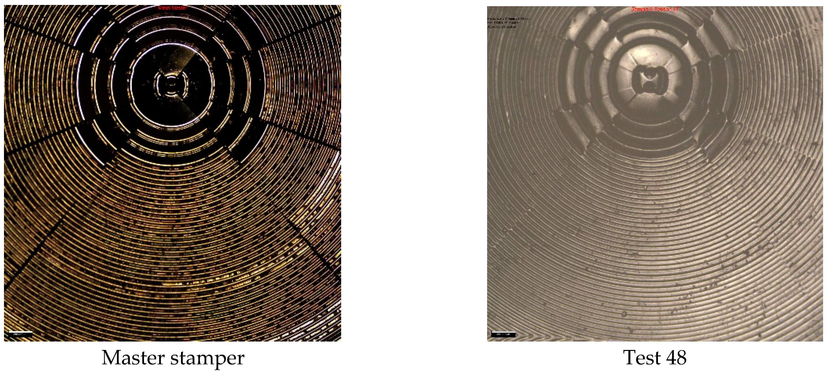
3.2. Replication
4. Discussion
5. Conclusions
- The first hypothesis (H1) established that the developed VS conditions are correctly set for the cold embossing process. Gloss analysis is performed on the parts to test H1. The pooled average of all 169 measurements show that the VS has a significant influence on gloss on the test parts. The GU result evidences that surface softening has occurred, which is a pre-condition for cold embossing.
- Conventional HE of polymers is a time-consuming process. In this research the second hypothesis (H2) establishes that a high-speed automation process with correctly controlled factors for cold embossing can imprint Fresnel lens design features onto 3D-printed ABS parts. It was demonstrated that 48 embosses can be performed in just over one minute.
- Replication quality is dependent on embossing time (Et) and embossing velocity (Ev). A low Et of 0.01 s resulted in no observed replication of the lens features. In contrast, an increase in Et to 0.1 s yielded optimal results, with all tests across 48 segments of the test piece successfully embossed.
- This study reveals that polymer flow is hindered by insufficient cycle times, but excessive durations lead to surface-hardening of the polymer, obstructing effective replication.
Author Contributions
Funding
Data Availability Statement
Conflicts of Interest
Abbreviations
| DOEs | Diffractive Optical Elements |
| HE | Hot Embossing |
| CE | Cold Embossing |
| ABS | Acrylonitrile Butadiene Styrene |
| FDM | Fused Deposition Modelling |
| VS | Vapour Smoothing |
| IPA | Isopropyl Alcohol |
| GU | Gloss Unit |
| ADC | Analogue to Digital Converter |
| DAQ | Data Acquisition System |
| IM | Injection Moulding |
| Tg | Glass Transition Temperature |
| Fe | Embossing Force |
| Tm | Embossing Temperature |
| Pe | Embossing Pressure |
| Et | Embossing Time |
| Ev | Embossing velocity |
| MEMS | Micro-Electro Mechanical Systems |
| PMMA | Poly Methyl Meth Acrylate |
| DLP | Digital Light Processing |
| DLIP | Direct Laser Interference Patterning |
| SLA | Stereolithography |
| UV | Ultra Violet |
| AM | Additive Manufacturing |
References
- O’Shea, D.C.; Suleski, T.J.; Kathman, A.D.; Prather, D.W. Diffractive Optics: Design, Fabrication, and Test; SPIE: Bellingham, WA, USA, 2003. [Google Scholar] [CrossRef]
- Mohammad, N.; Meem, M.; Shen, B.; Wang, P.; Menon, R. Broadband Imaging with One Planar Diffractive Lens. Sci. Rep. 2018, 8, 2799. [Google Scholar] [CrossRef] [PubMed]
- Li, Y. Light Beams with Flat-Topped Profiles. Opt. Lett. 2002, 27, 1007–1009. [Google Scholar] [CrossRef] [PubMed]
- Golub, M.A.; Grossinger, I. Diffractive Optical Elements for Biomedical Applications; Baldini, F., Croitoru, N.I., Dickinson, M.R., Frenz, M., Miyagi, M., Pratesi, R., Seeger, S., Eds.; SPIE: San Remo, Italy, 1998; pp. 220–231. [Google Scholar] [CrossRef]
- Boonruang, S.; Mohammed, W.S. Integrated Diffractive Optical Elements for Optical Sensors Applications. In Proceedings of the 2011 2nd International Conference on Photonics, Kota Kinabalu, Malaysia, 17–19 October 2011; pp. 1–5. [Google Scholar] [CrossRef]
- Alió, J.L.; Pikkel, J. (Eds.) Multifocal Intraocular Lenses: The Art and the Practice; Essentials in Ophthalmology; Springer International Publishing: Cham, Switzerland, 2019. [Google Scholar] [CrossRef]
- Deshmukh, S.S.; Goswami, A. Hot Embossing of Polymers—A Review. Mater. Today Proc. 2020, 26, 405–414. [Google Scholar] [CrossRef]
- Lin, C.-R.; Chen, R.-H.; Hung, C. Preventing Non-Uniform Shrinkage in Open-Die Hot Embossing of PMMA Microstructures. J. Mater. Process. Technol. 2003, 140, 173–178. [Google Scholar] [CrossRef]
- Worgull, M. Hot Embossing: Theory and Technology of Microreplication; Micro & nano technologies; William Andrew: Oxford, UK; Burlington, MA, USA, 2009. [Google Scholar]
- Heckele, M.; Schomburg, W.K. Review on Micro Molding of Thermoplastic Polymers. J. Micromech. Microeng. 2004, 14, R1–R14. [Google Scholar] [CrossRef]
- Deshmukh, S.S.; Goswami, A. Microlens Array through Induction-Aided Hot Embossing: Fabrication, Optimization, and Characterization. Mater. Manuf. Process. 2022, 37, 1540–1554. [Google Scholar] [CrossRef]
- Deshmukh, S.S.; Goswami, A. Current Innovations in Roller Embossing—A Comprehensive Review. Microsyst. Technol. 2022, 28, 1077–1114. [Google Scholar] [CrossRef]
- Heckele, M.; Bacher, W.; Müller, K.D. Hot Embossing—The Molding Technique for Plastic Microstructures. Microsyst. Technol. 1998, 4, 122–124. [Google Scholar] [CrossRef]
- Worgull, M.; Hétu, J.-F.; Kabanemi, K.K.; Heckele, M. Hot Embossing of Microstructures: Characterization of Friction during Demolding. Microsyst. Technol. 2008, 14, 767–773. [Google Scholar] [CrossRef]
- Chen, Q.; Zhang, L.; Chen, G. Far Infrared-Assisted Embossing and Bonding of Poly(Methyl Methacrylate) Microfluidic Chips. RSC Adv. 2014, 4, 56440–56444. [Google Scholar] [CrossRef]
- He, Y.; Wu, W.; Zhang, T.; Fu, J. Micro Structure Fabrication with a Simplified Hot Embossing Method. RSC Adv. 2015, 5, 39138–39144. [Google Scholar] [CrossRef]
- Çoğun, F.; Yıldırım, E.; Sahir Arikan, M.A. Investigation on Replication of Microfluidic Channels by Hot Embossing. Mater. Manuf. Process. 2017, 32, 1838–1844. [Google Scholar] [CrossRef]
- Melentiev, R.; Lubineau, G. Large-Scale Hot Embossing of 1 Μm High-Aspect-Ratio Textures on ABS Polymer. CIRP J. Manuf. Sci. Technol. 2022, 38, 340–349. [Google Scholar] [CrossRef]
- Gao, J.; Deng, Y.; Peng, L.; Yi, P.; Lin, Z. Water-Repellent Hierarchical Microstructured PTFE Films via Micro Powder Hot Embossing. J. Mater. Process. Technol. 2021, 297, 117261. [Google Scholar] [CrossRef]
- Hu, M.; Xie, J.; Li, W.; Lu, K. Study on Non-Isothermal Hot-Embossing of Polymer Micro-Prism Array with Efficiency and Accuracy. J. Mater. Process. Technol. 2019, 266, 675–686. [Google Scholar] [CrossRef]
- Sahli, M.; Millot, C.; Gelin, J.-C.; Barrière, T. The Manufacturing and Replication of Microfluidic Mould Inserts by the Hot Embossing Process. J. Mater. Process. Technol. 2013, 213, 913–925. [Google Scholar] [CrossRef]
- Cheng, G.; Sahli, M.; Gelin, J.-C.; Barriere, T. Physical Modelling, Numerical Simulation and Experimental Investigation of Microfluidic Devices with Amorphous Thermoplastic Polymers Using a Hot Embossing Process. J. Mater. Process. Technol. 2016, 229, 36–53. [Google Scholar] [CrossRef]
- Ng, S.H.; Wang, Z.F. Hot Roller Embossing for Microfluidics: Process and Challenges. Microsyst. Technol. 2009, 15, 1149–1156. [Google Scholar] [CrossRef]
- Huang, M.; Chiang, Y.; Lin, S.; Cheng, H.; Huang, C.; Shen, Y.; Lin, Y. Fabrication of Microfluidic Chip Using Micro-hot Embossing with Micro Electrical Discharge Machining Mold. Polym. Adv. Technol. 2012, 23, 57–64. [Google Scholar] [CrossRef]
- Moore, S.; Gomez, J.; Lek, D.; You, B.H.; Kim, N.; Song, I.-H. Experimental Study of Polymer Microlens Fabrication Using Partial-Filling Hot Embossing Technique. Microelectron. Eng. 2016, 162, 57–62. [Google Scholar] [CrossRef]
- Huang, C.-Y.; Tsai, M.-S. Fabrication of 3D Nano-Hemispherical Cavity Array Plasmonic Substrate for SERS Applications. Int. J. Optomechatron. 2018, 12, 40–52. [Google Scholar] [CrossRef]
- Roeder, M.; Guenther, T.; Zimmermann, A. Review on Fabrication Technologies for Optical Mold Inserts. Micromachines 2019, 10, 233. [Google Scholar] [CrossRef] [PubMed]
- Kafka, J.; Larsen, N.B.; Skaarup, S.; Geschke, O. Fabrication of an All-Polymer Electrochemical Sensor by Using a One-Step Hot Embossing Procedure. Microelectron. Eng. 2010, 87, 1239–1241. [Google Scholar] [CrossRef]
- Saito, H.; Komatsuzaki, H.; Ikoma, R.; Komori, T.; Kuroda, K.; Kimura, Y.; Fukushi, Y.; Maenosono, H.; Koide, S.; Satano, M.; et al. Electroosmotic Flow Pump on Transparent Polyimide Substrate Fabricated Using Hot Embossing. Appl. Mech. Mater. 2013, 300–301, 1356–1359. [Google Scholar] [CrossRef]
- Chang, C.-Y.; Yu, C.-H. A Basic Experimental Study of Ultrasonic Assisted Hot Embossing Process for Rapid Fabrication of Microlens Arrays. J. Micromech. Microeng. 2015, 25, 025010. [Google Scholar] [CrossRef]
- Yang, S.-Y.; Huang, T.-C.; Ciou, J.-K.; Chan, B.-D.; Loeser, J.G. CO2—Assisted Embossing for the Fabrication of PMMA Components under Low Temperature and with Low Pressure. J. Micromech. Microeng. 2008, 18, 025024. [Google Scholar] [CrossRef]
- Wu, J.-T.; Chu, Y.-T.; Yang, S.-Y.; Li, C.-C. Low-Temperature Embossing Technique for Fabrication of Large-Area Polymeric Microlens Array with Supercritical Carbon Dioxide. Microelectron. Eng. 2010, 87, 2620–2624. [Google Scholar] [CrossRef]
- Abubaker, S.S.; Zhang, Y. Optimization Design and Fabrication of Polymer Micro Needle by Hot Embossing Method. Int. J. Precis. Eng. Manuf. 2019, 20, 631–640. [Google Scholar] [CrossRef]
- Guo, Y.; Liu, G.; Xiong, Y.; Wang, J.; Huang, X.; Tian, Y. Study of Hot Embossing Using Nickel and Ni–PTFE LIGA Mold Inserts. J. Microelectromech. Syst. 2007, 16, 589–597. [Google Scholar] [CrossRef]
- Wang, J.; Yi, P.; Deng, Y.; Peng, L.; Lai, X.; Ni, J. Recovery Behavior of Thermoplastic Polymers in Micro Hot Embossing Process. J. Mater. Process. Technol. 2017, 243, 205–216. [Google Scholar] [CrossRef]
- Worgull, M.; Heckele, M. New Aspects of Simulation in Hot Embossing. Microsyst. Technol. 2004, 10, 432–437. [Google Scholar] [CrossRef]
- Boinski, A.-K.; Riemer, O.; Karpuschewski, B.; Schneider, M.; Guttmann, M.; Worgull, M. Fast Tool Machining and Hot Embossing for the Manufacture of Diffractive Structured Surfaces. Precis. Eng. 2022, 74, 12–19. [Google Scholar] [CrossRef]
- Fang-Yu, F.; Hsin-Chung, C.; Chiung-Fang, H.; Yi, L.; Wei-Chun, L.; Yung-Kang, S.; Liping, W. Replicability of Process Conditions of Ultrasonic Hot Embossing for Micropattern Fabrication on Thermoplastic Substrates. J. Manuf. Process. 2020, 60, 283–291. [Google Scholar] [CrossRef]
- Sha, B.; Dimov, S.; Griffiths, C.; Packianather, M.S. Investigation of Micro-Injection Moulding: Factors Affecting the Replication Quality. J. Mater. Process. Technol. 2007, 183, 284–296. [Google Scholar] [CrossRef]
- Long, M.; Peng, S.; Chen, J.; Yang, X.; Deng, W. A New Replication Method for Fabricating Hierarchical Polymer Surfaces with Robust Superhydrophobicity and Highly Improved Oleophobicity. Colloids Surf. Physicochem. Eng. Asp. 2016, 507, 7–17. [Google Scholar] [CrossRef]
- Rooney, L.M.; Christopher, J.; Watson, B.; Kumar, Y.S.; Copeland, L.; Walker, L.D.; Foylan, S.; Amos, W.B.; Bauer, R.; McConnell, G. Printing, Characterizing, and Assessing Transparent 3D Printed Lenses for Optical Imaging. Adv. Mater. Technol. 2024, 9, 2400043. [Google Scholar] [CrossRef]
- Alam, F.; Elsherif, M.; AlQattan, B.; Salih, A.; Lee, S.M.; Yetisen, A.K.; Park, S.; Butt, H. 3D Printed Contact Lenses. ACS Biomater. Sci. Eng. 2021, 7, 794–803. [Google Scholar] [CrossRef]
- Sun, Q.; Fang, F.; Wang, W.; Yin, J.; Liu, Q.; Hao, L.; Peng, Y. Stereolithography 3D Printing of Transparent Resin Lens for High-Power Phosphor-Coated WLEDs Packaging. J. Manuf. Process. 2023, 85, 756–763. [Google Scholar] [CrossRef]
- Ali, M.; Alam, F.; Ahmed, I.; AlQattan, B.; Yetisen, A.K.; Butt, H. 3D Printing of Fresnel Lenses with Wavelength Selective Tinted Materials. Addit. Manuf. 2021, 47, 102281. [Google Scholar] [CrossRef]
- Muntaha, S.T.; Hokkanen, A.; Harjanne, M.; Cherchi, M.; Suopajärvi, P.; Karvinen, P.; Pekkarinen, M.; Roussey, M.; Aalto, T. 3D Printed Lenses for Vertical Beam Collimation of Optical Phased Arrays. 3D Print. Addit. Manuf. 2024, 11, e1227–e1234. [Google Scholar] [CrossRef]
- Ma, Q.; Dong, K.; Li, F.; Jia, Q.; Tian, J.; Yu, M.; Xiong, Y. Additive Manufacturing of Polymer Composite Millimeter-wave Components: Recent Progress, Novel Applications, and Challenges. Polym. Compos. 2025, 46, 14–37. [Google Scholar] [CrossRef]
- Vera, J.; Brulez, A.-C.; Contraires, E.; Larochette, M.; Trannoy-Orban, N.; Pignon, M.; Mauclair, C.; Valette, S.; Benayoun, S. Factors Influencing Microinjection Molding Replication Quality. J. Micromechanics Microengineering 2018, 28, 015004. [Google Scholar] [CrossRef]
- Toth, G.; Nagy, D.; Bata, A.; Belina, K. Determination of Polymer Melts Flow-Activation Energy a Function of Wide Range Shear Rate. J. Phys. Conf. Ser. 2018, 1045, 012040. [Google Scholar] [CrossRef]
- Lou, Y.; Lei, Q.; Wu, G. Research on Polymer Viscous Flow Activation Energy and Non-Newtonian Index Model Based on Feature Size. Adv. Polym. Technol. 2019, 2019, 1070427. [Google Scholar] [CrossRef]
- Hwang, S.; Reyes, E.I.; Moon, K.; Rumpf, R.C.; Kim, N.S. Thermo-Mechanical Characterization of Metal/Polymer Composite Filaments and Printing Parameter Study for Fused Deposition Modeling in the 3D Printing Process. J. Electron. Mater. 2015, 44, 771–777. [Google Scholar] [CrossRef]
- Shen, X.-J.; Pan, L.-W.; Lin, L. Microplastic Embossing Process: Experimental and Theoretical Characterizations. Sens. Actuators Phys. 2002, 97–98, 428–433. [Google Scholar] [CrossRef]
- Zhu, X.; Simon, T.W.; Cui, T. Hot Embossing at Viscous State to Enhance Filling Process for Complex Polymer Structures. Microsyst. Technol. 2012, 18, 257–265. [Google Scholar] [CrossRef]
- McCullough, E.J.; Yadavalli, V.K. Surface Modification of Fused Deposition Modeling ABS to Enable Rapid Prototyping of Biomedical Microdevices. J. Mater. Process. Technol. 2013, 213, 947–954. [Google Scholar] [CrossRef]
- Singh, R.; Singh, S.; Singh, I.P.; Fabbrocino, F.; Fraternali, F. Investigation for Surface Finish Improvement of FDM Parts by Vapor Smoothing Process. Compos. Part B Eng. 2017, 111, 228–234. [Google Scholar] [CrossRef]
- Lalehpour, A.; Janeteas, C.; Barari, A. Surface Roughness of FDM Parts after Post-Processing with Acetone Vapor Bath Smoothing Process. Int. J. Adv. Manuf. Technol. 2018, 95, 1505–1520. [Google Scholar] [CrossRef]
- John Rajan, A.; Sugavaneswaran, M.; Prashanthi, B.; Deshmukh, S.; Jose, S. Influence of Vapour Smoothing Process Parameters on Fused Deposition Modelling Parts Surface Roughness at Different Build Orientation. Mater. Today Proc. 2020, 22, 2772–2778. [Google Scholar] [CrossRef]
- Singh, J.; Singh, R.; Singh, H. Repeatability of Linear and Radial Dimension of ABS Replicas Fabricated by Fused Deposition Modelling and Chemical Vapor Smoothing Process: A Case Study. Measurement 2016, 94, 5–11. [Google Scholar] [CrossRef]
- Garg, A.; Bhattacharya, A.; Batish, A. On Surface Finish and Dimensional Accuracy of FDM Parts after Cold Vapor Treatment. Mater. Manuf. Process. 2016, 31, 522–529. [Google Scholar] [CrossRef]
- Kuo, C.-C.; Mao, R.-C. Development of a Precision Surface Polishing System for Parts Fabricated by Fused Deposition Modeling. Mater. Manuf. Process. 2016, 31, 1113–1118. [Google Scholar] [CrossRef]
- Singh, T.H.B.; Chohan, J.S.; Kumar, R. Performance Analysis of Vapour Finishing Apparatus for Surface Enhancement of FDM Parts. Mater. Today Proc. 2020, 26, 3497–3502. [Google Scholar] [CrossRef]
- Yadav, A.; Poorna Prakash, B.; Sai Dileep, K.; Arjuna Rao, S.; Veeresh Kumar, G.B. An Experimental Examination on Surface Finish of FDM 3D Printed Parts. Mater. Today Proc. 2024, 115, 148–155. [Google Scholar] [CrossRef]
- ISO 2813; Paints and Varnishes—Determination of Gloss Value at 20°, 60° and 85°. ISO: Geneva, Switzerland, 2014.
- ASTM D523; Standard Test Method for Specular Gloss. ASTM: West Conshohocken, PA, USA, 2014.
- ISO 17025; General Requirements for the Competence of Testing and Calibration Laboratories. ISO: Geneva, Switzerland, 2017.


| Parameter | Setting |
|---|---|
| Initial Layer Height | 0.2 mm |
| Layer Height | 0.1 mm and 0.3 mm |
| Nozzle Diameter | 0.4 mm |
| Initial Line Width | 0.5 mm |
| Line Width | 0.42 mm |
| Outer Wall | 0.42 mm |
| Inner Wall | 0.45 |
| Top Surface | 0.42 |
| Seam Alignment | Back |
| Wall Line Count | 2 |
| Top Layers | 5 |
| Top Surface Pattern | Monotonic Line |
| Bottom Layers | 5 |
| Infill Pattern | Rectilinear |
| Infill Density | 100% |
| Supports | Off |
| Build Plate Adhesion | None |
| Printing Temperature | 260 °C |
| Build Plate Temperature | 90 °C |
| Material group | 100,043 |
| CAS Reg No | 67-64-1 |
| Density @20 °C | 0.789–0.792 |
| Water (% Mass) | 0.3% |
| Refractive index @20 °C | 1.359 |
| Assay (% Mass) | 99.8 |
| Acidity (As Acebic Acid)—(% Mass) | Max 0.002 |
| Mean 97.3 N | SE Mean 1.82 | StDev 5.16 |
| 95% confidence mean for F measurements is between 93.0 and 101.7 N | ||
| 95% confidence for median F is between 94.0 and 100.5 N | ||
| 95% confidence interval for StDev of 3.14 to 10.5 | ||
| Experiment | Et (s) | Ev (mm/s) | Total Cycle Time (ms) | Average Cycle Time/Test (ms) |
|---|---|---|---|---|
| 1 | 1.0 | 0.1 | 21,780 | 454 |
| 2 | 0.1 | 0.01 | 60,228 | 1254 |
| 3 | 0.01 | 0.001 | 449,472 | 9364 |
| Sample | Mean | StDev | SE Mean |
|---|---|---|---|
| VS | 31.23 | 8.44 | 0.69 |
| Non-VS | 2.085 | 0.036 | 0.008 |
| T-Value | DF | p-Value | |
| 42.13 | 148 | 0.000 | |
Disclaimer/Publisher’s Note: The statements, opinions and data contained in all publications are solely those of the individual author(s) and contributor(s) and not of MDPI and/or the editor(s). MDPI and/or the editor(s) disclaim responsibility for any injury to people or property resulting from any ideas, methods, instructions or products referred to in the content. |
© 2025 by the authors. Licensee MDPI, Basel, Switzerland. This article is an open access article distributed under the terms and conditions of the Creative Commons Attribution (CC BY) license (https://creativecommons.org/licenses/by/4.0/).
Share and Cite
Griffiths, C.A.; Rees, A.; Morgan, A.J.; Thomas, A.J. Automated Cold Embossing for the Integration of Optical Lenses onto the Surface of Acrylonitrile Butadiene Styrene (ABS) 3D-Printed Parts. Polymers 2025, 17, 1745. https://doi.org/10.3390/polym17131745
Griffiths CA, Rees A, Morgan AJ, Thomas AJ. Automated Cold Embossing for the Integration of Optical Lenses onto the Surface of Acrylonitrile Butadiene Styrene (ABS) 3D-Printed Parts. Polymers. 2025; 17(13):1745. https://doi.org/10.3390/polym17131745
Chicago/Turabian StyleGriffiths, Christian A., Andrew Rees, Adam J. Morgan, and Andrew J. Thomas. 2025. "Automated Cold Embossing for the Integration of Optical Lenses onto the Surface of Acrylonitrile Butadiene Styrene (ABS) 3D-Printed Parts" Polymers 17, no. 13: 1745. https://doi.org/10.3390/polym17131745
APA StyleGriffiths, C. A., Rees, A., Morgan, A. J., & Thomas, A. J. (2025). Automated Cold Embossing for the Integration of Optical Lenses onto the Surface of Acrylonitrile Butadiene Styrene (ABS) 3D-Printed Parts. Polymers, 17(13), 1745. https://doi.org/10.3390/polym17131745