
Comparative Analysis of Dimensional Accuracy in PLA-Based 3D Printing: Effects of Key Printing Parameters and Related Variables


Abstract
1. Introduction
2. Results and Discussion
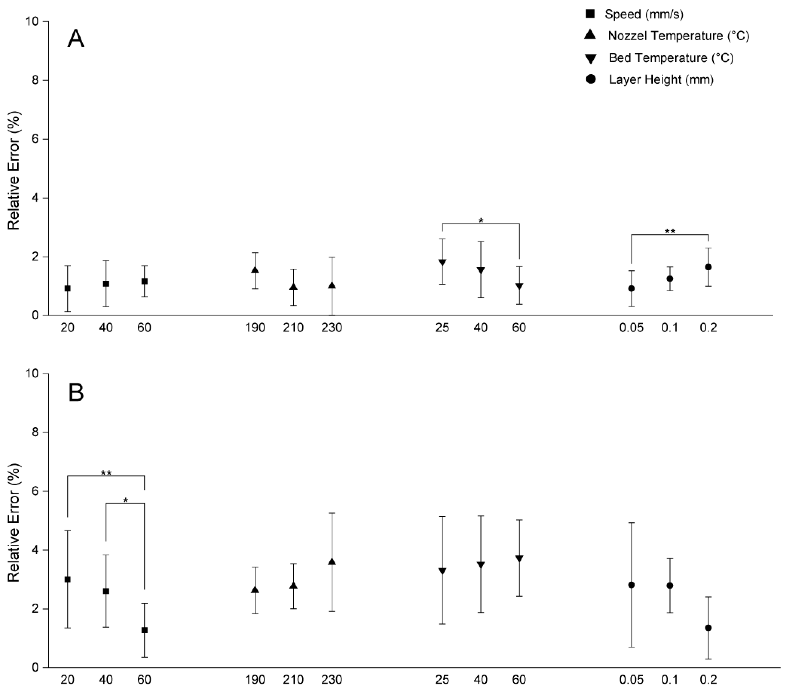
2.1. Influence of Printing Speed
2.2. Influence of Nozzle Temperature
2.3. Influence of Bed Temperature
2.4. Influence of Layer Height on Dimensional Errors
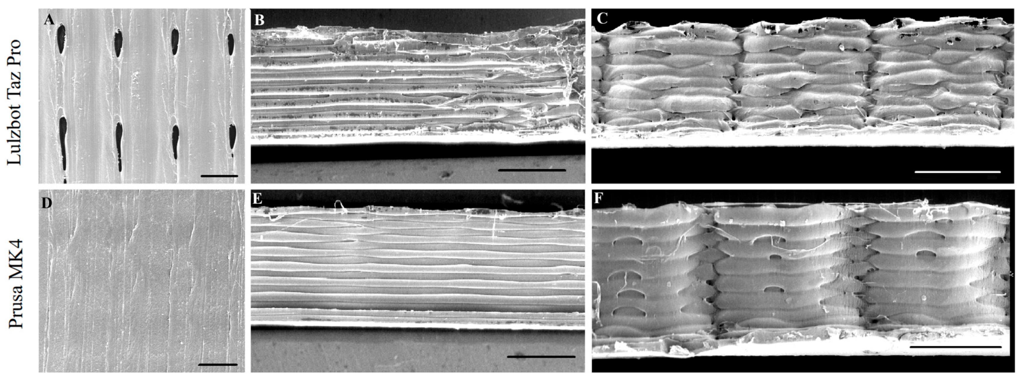
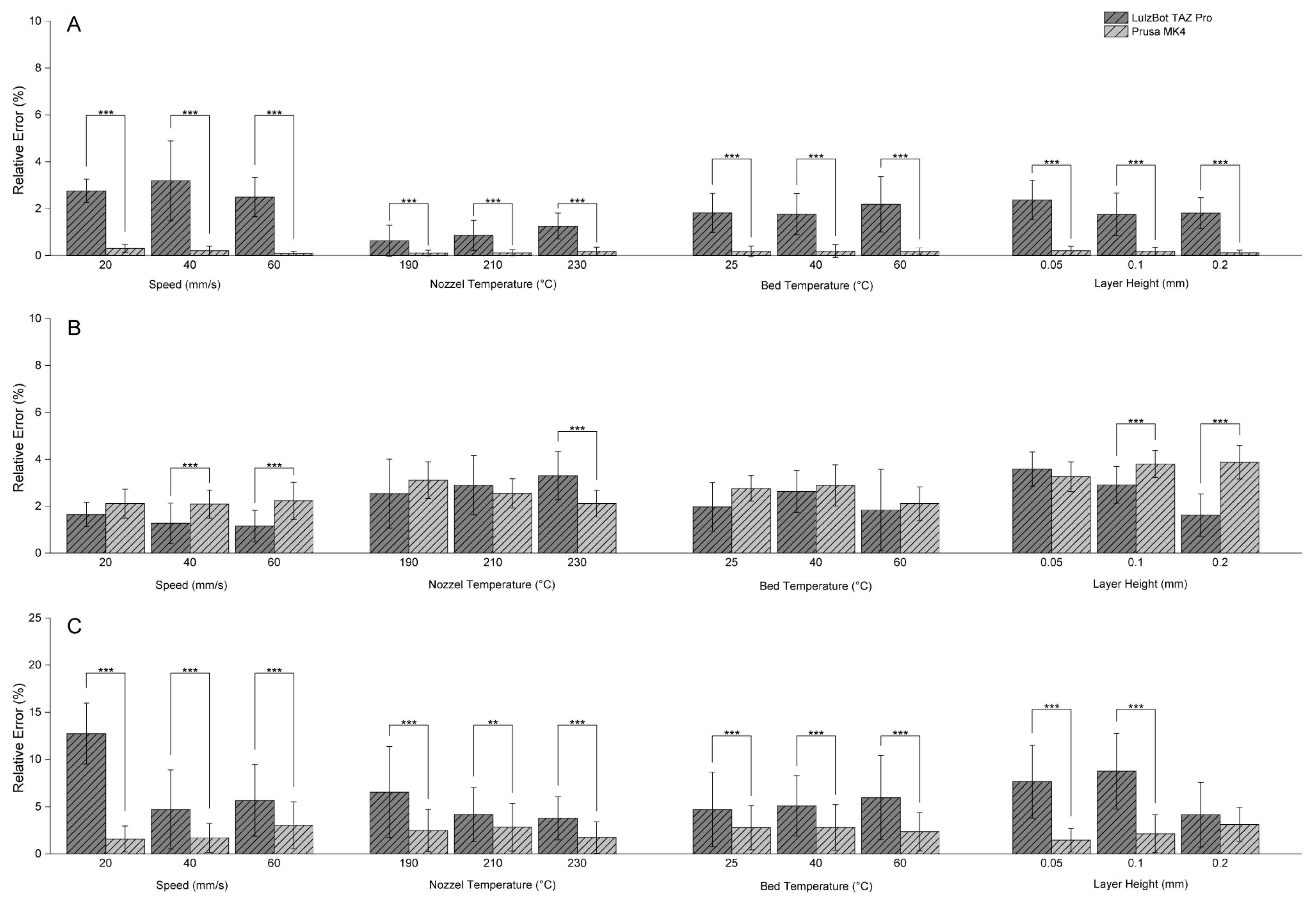
2.5. Comparison of Dimensional Accuracy Between the Two 3D Printers
3. Materials and Methods
3.1. Sample Preparation
3.2. Measurement of Dimensional Accuracy
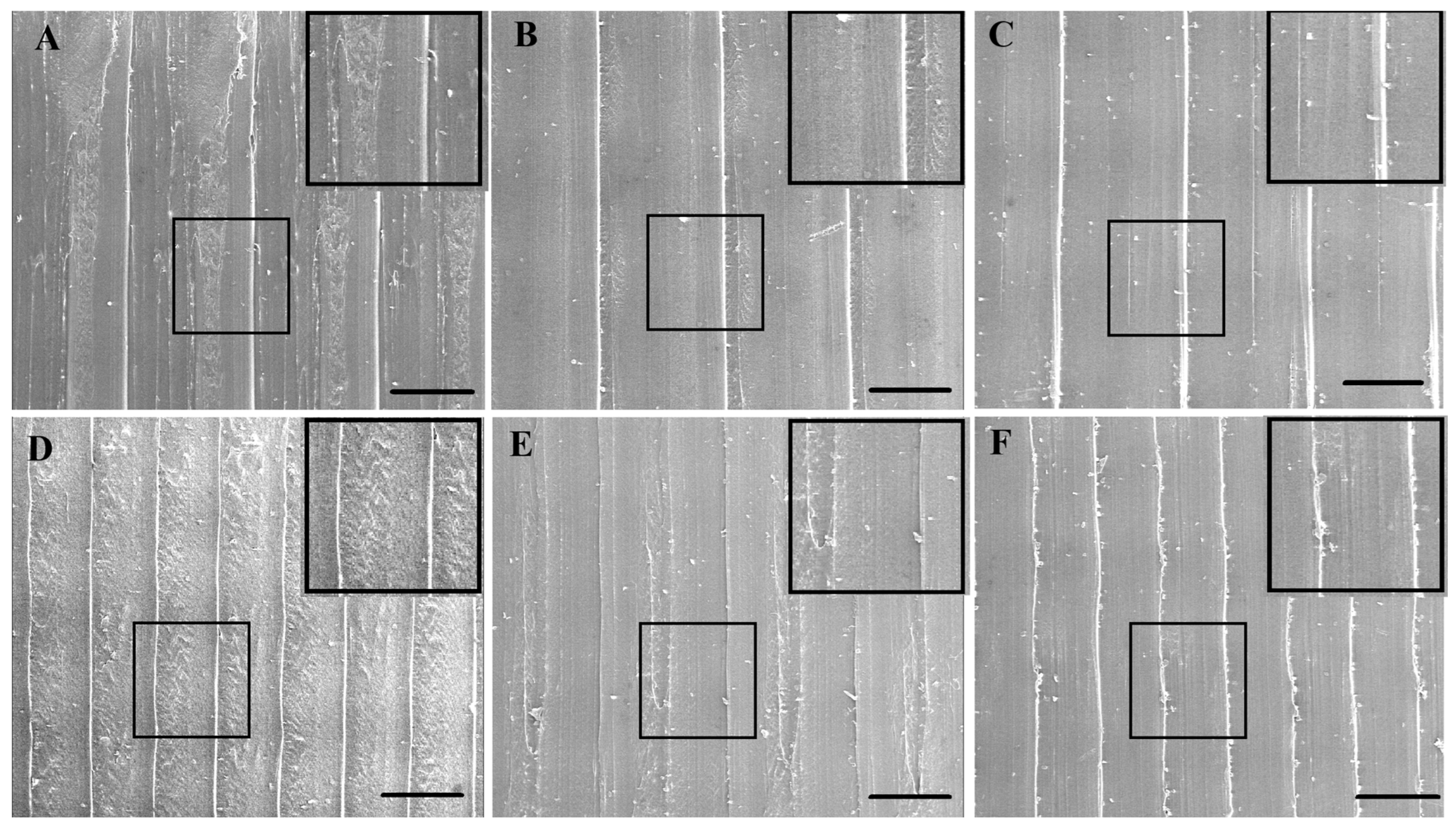
3.3. Scanning Electron Microscopy
3.4. Statistical Analysis
4. Conclusions
Author Contributions
Funding
Institutional Review Board Statement
Data Availability Statement
Acknowledgments
Conflicts of Interest
References
- Butelmann, T.; Gu, Y.; Li, A.; Tribukait-Riemenschneider, F.; Hoffmann, J.; Molazem, A.; Jaeger, E.; Pellegrini, D.; Forget, A.; Shastri, V.P. 3D Printed Solutions for Spheroid Engineering and Cancer Research. Int. J. Mol. Sci. 2022, 23, 8188. [Google Scholar] [CrossRef]
- Luo, M.; Wang, W.; Yang, N.; Xia, L. Does Three-dimensional Printing Plus Pedicle Guider Technology in Severe Congenital Scoliosis Facilitate Accurate and Efficient Pedicle Screw Placement? Clin. Orthop. Relat. Res. 2019, 477, 1904–1912. [Google Scholar] [CrossRef] [PubMed]
- Sun, M.L.; Zhang, Y.; Peng, Y.; Fu, D.J.; Fan, H.Q.; He, R. Accuracy of a Novel 3D-Printed Patient-Specific Intramedullary Guide to Control Femoral Component Rotation in Total Knee Arthroplasty. Orthop. Surg. 2020, 12, 429–441. [Google Scholar] [CrossRef]
- Buj-Corral, I.; Zayas-Figueras, E.E. Comparative study about dimensional accuracy and form errors of FFF printed spur gears using PLA and Nylon. Polym. Test. 2023, 117, 107862. [Google Scholar] [CrossRef]
- Johann, K.S.; Böhm, F.; Kapernaum, N.; Giesselmann, F.; Bonten, C. Orientation of Liquid Crystalline Polymers after Filament Extrusion and after Passing through a 3D Printer Nozzle. ACS Appl. Polym. Mater. 2024, 6, 10006–10018. [Google Scholar] [CrossRef]
- Frunzaverde, D.; Cojocaru, V.; Ciubotariu, C.R.; Miclosina, C.O.; Ardeljan, D.D.; Ignat, E.F.; Marginean, G. The Influence of the Printing Temperature and the Filament Color on the Dimensional Accuracy, Tensile Strength, and Friction Performance of FFF-Printed PLA Specimens. Polymers 2022, 14, 1978. [Google Scholar] [CrossRef]
- Maines, E.M.; Porwal, M.K.; Ellison, C.J.; Reineke, T.M. Sustainable advances in SLA/DLP 3D printing materials and processes. Green Chem. 2021, 23, 6863–6897. [Google Scholar] [CrossRef]
- Zhang, J.; Tong, D.; Song, H.; Ruan, R.; Sun, Y.; Lin, Y.; Wang, J.; Hou, L.; Dai, J.; Ding, J.; et al. Osteoimmunity-Regulating Biomimetically Hierarchical Scaffold for Augmented Bone Regeneration. Adv. Mater. 2022, 34, e2202044. [Google Scholar] [CrossRef]
- Ninikas, K.; Kechagias, J.; Fountas, N.A.; Vaxevanidis, N.M. A study of Fused Filament Fabrication process efficiency: ABS vs PLA materials. IOP Conf. Ser. Mater. Sci. Eng. 2022, 1235, 012007. [Google Scholar] [CrossRef]
- Arnal-Burro, J.; Perez-Mananes, R.; Gallo-Del-Valle, E.; Igualada-Blazquez, C.; Cuervas-Mons, M.; Vaquero-Martin, J. Three dimensional-printed patient-specific cutting guides for femoral varization osteotomy: Do it yourself. Knee 2017, 24, 1359–1368. [Google Scholar] [CrossRef]
- Luis-Perez, C.J.; Buj-Corral, I.; Sanchez-Casas, X. Modeling of the Influence of Input AM Parameters on Dimensional Error and Form Errors in PLA Parts Printed with FFF Technology. Polymers 2021, 13, 4152. [Google Scholar] [CrossRef]
- Buj-Corral, I.; Bagheri, A.; Sivatte-Adroer, M. Effect of Printing Parameters on Dimensional Error, Surface Roughness and Porosity of FFF Printed Parts with Grid Structure. Polymers 2021, 13, 1213. [Google Scholar] [CrossRef] [PubMed]
- Abas, M.; Habib, T.; Noor, S.; Salah, B.; Zimon, D. Parametric Investigation and Optimization to Study the Effect of Process Parameters on the Dimensional Deviation of Fused Deposition Modeling of 3D Printed Parts. Polymers 2022, 14, 3667. [Google Scholar] [CrossRef]
- Zhang, Y.; Mao, K.; Leigh, S.; Shah, A.; Chao, Z.M.; Ma, G.T. A parametric study of 3D printed polymer gears. Int. J. Adv. Manuf. Technol. 2020, 107, 4481–4492. [Google Scholar] [CrossRef]
- Gendviliene, I.; Simoliunas, E.; Rekstyte, S.; Malinauskas, M.; Zaleckas, L.; Jegelevicius, D.; Bukelskiene, V.; Rutkunas, V. Assessment of the morphology and dimensional accuracy of 3D printed PLA and PLA/HAp scaffolds. J. Mech. Behav. Biomed. Mater. 2020, 104, 103616. [Google Scholar] [CrossRef] [PubMed]
- Pyka, D.; Słowiński, J.J.; Kurzawa, A.; Roszak, M.; Stachowicz, M.; Kazimierczak, M.; Stępczak, M.; Grygier, D. Research on Basic Properties of Polymers for Fused Deposition Modelling Technology. Appl. Sci. 2024, 14, 11151. [Google Scholar] [CrossRef]
- Fales, A.; Cernohlavek, V.; Sterba, J.; Dian, M.; Suszynski, M. Innovative Approaches to Material Selection and Testing in Additive Manufacturing. Materials 2025, 18, 144. [Google Scholar] [CrossRef] [PubMed]
- Vochozka, V.; Cerny, P.; Sramhauser, K.; Spalek, F.; Kriz, P.; Cech, J.; Zoubek, T.; Bartos, P.; Kresan, J.; Stehlik, R. Fused Filament Fabrication 3D Printing Parameters Affecting the Translucency of Polylactic Acid Parts. Polymers 2024, 16, 2862. [Google Scholar] [CrossRef]
- Delanoe, K.; Salaun, E.; Rieu, R.; Cote, N.; Pibarot, P.; Stanova, V. Advanced Silicon Modeling of Native Mitral Valve Physiology: A New Standard for Device and Procedure Testing. Bioengineering 2025, 12, 397. [Google Scholar] [CrossRef]
- Pan, F.; Sui, J.; Silva-Pedraza, Z.; Bontekoe, J.; Carlos, C.R.; Wu, G.; Liu, W.; Gao, J.; Liu, B.; Wang, X. 3D-Printed Piezoelectric Stents for Electricity Generation Driven by Pressure Fluctuation. ACS Appl. Mater. Interfaces 2024, 16, 27705–27713. [Google Scholar] [CrossRef]
- Sarkar, N.; Zhao, J.; Zhang, N.Y.; Horenberg, A.L.; Grayson, W.L. 3D printed O2-generating scaffolds enhance osteoprogenitor- and type H vessel recruitment during bone healing. Acta Biomater. 2024, 185, 126–143. [Google Scholar] [CrossRef]
- Chrz, K.; Bruthans, J.; Ptacnik, J.; Stuka, C. A Cost-Affordable Methodology of 3D Printing of Bone Fractures Using DICOM Files in Traumatology. J. Med. Syst. 2024, 48, 66. [Google Scholar] [CrossRef]
- Zhang, J.; Wang, X.Z.; Yu, W.W.; Deng, Y.H. Numerical investigation of the influence of process conditions on the temperature variation in fused deposition modeling. Mater. Des. 2017, 130, 59–68. [Google Scholar] [CrossRef]
- Galantucci, L.M.; Bodi, I.; Kacani, J.; Lavecchia, F. Analysis of dimensional performance for a 3D open-source printer based on fused deposition modeling technique. Procedia CIRP 2015, 28, 82–87. [Google Scholar] [CrossRef]
- Elkaseer, A.; Schneider, S.; Scholz, S.G. Experiment-Based Process Modeling and Optimization for High-Quality and Resource-Efficient FFF 3D Printing. Appl. Sci. 2020, 10, 2899. [Google Scholar] [CrossRef]
- Abas, M.; Salman, Q.; Khan, A.M.; Rahman, K. Direct ink writing of flexible electronic circuits and their characterization. J. Braz. Soc. Mech. Sci. Eng. 2019, 41, 563. [Google Scholar] [CrossRef]
- Akbaş, O.E.; Hıra, O.; Hervan, S.Z.; Samankan, S.; Altınkaynak, A. Dimensional accuracy of FDM-printed polymer parts. Rapid Prototyp. J. 2019, 26, 288–298. [Google Scholar] [CrossRef]
- Buj-Corral, I.; Sivatte-Adroer, M. An Experimental Investigation about the Dimensional Accuracy and the Porosity of Copper-Filled PLA Fused Filament Fabrication Parts. Metals 2023, 13, 1608. [Google Scholar] [CrossRef]
- Vyavahare, S.; Kumar, S.; Panghal, D. Experimental study of surface roughness, dimensional accuracy and time of fabrication of parts produced by fused deposition modelling. Rapid Prototyp. J. 2020, 26, 1535–1554. [Google Scholar] [CrossRef]
- Enemuoh, E.U.; Duginski, S.; Feyen, C.; Menta, V.G. Effect of Process Parameters on Energy Consumption, Physical, and Mechanical Properties of Fused Deposition Modeling. Polymers 2021, 13, 2406. [Google Scholar] [CrossRef]
- Beniak, J.; Križan, P.; Šooš, Ľ.; Matúš, M. Research on Shape and Dimensional Accuracy of FDM Produced Parts. IOP Conf. Ser. Mater. Sci. Eng. 2019, 501, 012030. [Google Scholar] [CrossRef]
- Grubbs, J.; Sousa, B.C.; Cote, D.L. Establishing a Framework for Fused Filament Fabrication Process Optimization: A Case Study with PLA Filaments. Polymers 2023, 15, 1945. [Google Scholar] [CrossRef] [PubMed]
- Jin, M.; Giesa, R.; Neuber, C.; Schmidt, H.W. Filament Materials Screening for FDM 3D Printing by Means of Injection-Molded Short Rods. Macromol. Mater. Eng. 2018, 303, 1800507. [Google Scholar] [CrossRef]
- Benwood, C.; Anstey, A.; Andrzejewski, J.; Misra, M.; Mohanty, A.K. Improving the Impact Strength and Heat Resistance of 3D Printed Models: Structure, Property, and Processing Correlationships during Fused Deposition Modeling (FDM) of Poly(Lactic Acid). ACS Omega 2018, 3, 4400–4411. [Google Scholar] [CrossRef] [PubMed]
- Alsoufi, M.S.; Elsayed, A.E. Surface Roughness Quality and Dimensional Accuracy—A Comprehensive Analysis of 100% Infill Printed Parts Fabricated by a Personal/Desktop Cost-Effective FDM 3D Printer. Mater. Sci. Appl. 2018, 9, 11–40. [Google Scholar] [CrossRef]
- Zisopol, D.G.; Minescu, M.; Iacob, D.V. A Theoretical-Experimental Study on the Influence of FDM Parameters on the Dimensions of Cylindrical Spur Gears Made of PLA. Eng. Technol. Appl. Sci. Res. 2023, 13, 10471–10477. [Google Scholar] [CrossRef]
- Hartmann, C.; van den Bosch, L.; Spiegel, J.; Rumschottel, D.; Gunther, D. Removal of Stair-Step Effects in Binder Jetting Additive Manufacturing Using Grayscale and Dithering-Based Droplet Distribution. Materials 2022, 15, 3798. [Google Scholar] [CrossRef]
- Zuniga, J.M. 3D Printed Antibacterial Prostheses. Appl. Sci. 2018, 8, 1651. [Google Scholar] [CrossRef]
- Zhou, J.; Pan, B.; Yang, Q.; Zhao, Y.; He, L.; Lin, L.; Sun, H.; Song, Y.; Yu, X.; Sun, Z.; et al. Three-dimensional autologous cartilage framework fabrication assisted by new additive manufactured ear-shaped templates for microtia reconstruction. J. Plast. Reconstr. Aesthetic Surg. 2016, 69, 1436–1444. [Google Scholar] [CrossRef]
- Kechagias, J.D.; Vidakis, N.; Petousis, M.; Mountakis, N. A multi-parametric process evaluation of the mechanical response of PLA in FFF 3D printing. Mater. Manuf. Process. 2022, 38, 941–953. [Google Scholar] [CrossRef]


| FDM 3D Printer | ||
|---|---|---|
| Manufacturer | Lulzbot TAZ Pro * | Prusa MK4 ** |
 | 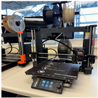 | |
| Print Area | 280 mm × 280 mm × 285 mm | 250 × 210 × 220 mm |
| Print Volume | 22.344 L | 11.550 L |
| Layer Resolution | 0.05 mm–0.4 mm | 0.05 mm—0.3 mm |
| Filament Diameter | 2.85 mm | 1.75 mm |
| Type’s of Extrusion | Direct Drive | Direct Drive |
| Print Bed | Not Removeable Borosilicate Glass with PEI Surface | Removeable Smooth PEI Print Sheet |
| Calibration | Automatic | Automatic Mesh Bed Leveling |
| Max Nozzle Temperature | 290 °C | 290 °C |
| Max Heat Bed Temperature | 100 °C | 120 °C |
| Nozzle Material | Brass—V6 Extra E3D | Brass—V6 |
| Polymaker Polylite PLA * | Recommended Print Settings | ||
|---|---|---|---|
| Nozzle Temperature | 190–230 | °C | |
| Bed Temperature | 25–60 | °C | |
| Nozzle Speed | 40–60 | mm/s | |
| Cooling Fan | On | - | |
| Density | 1.17–1.24 | g/cm3 @21.5 °C | ASTM D792 |
| Glass transition Temperature | 61 | °C | DSC, 10 °C/min |
| Melt Index | 7–11 | g/10 min | 210 °C, 216 kg |
| Melting Temperature | 150 | °C | DSC, 10 °C/min |
| Crystallization Temperature | 114 | °C | DSC, 10 °C/min |
| Young’s Modulus (X-Y) | 2636 ± 330 | MPa | ASTM D638 |
| Tensile Strength (X-Y) | 46.6 ± 0.9 | MPa | ASTM D638 |
| Device | LulzBot Taz Pro | Prusa MK4 | Unit |
|---|---|---|---|
| Extruder | Right | Main | - |
| Nozzle Diameter | 0.4 | 0.4 | mm |
| Extrusion Multiplier | 1 | 1 | - |
| Retract Distance | 1 | 1 | mm |
| Retract Speed | 10 | 10 | mm/s |
| Top Solid Layer | 0 | 0 | - |
| Bottom Solid Layer | 0 | 0 | - |
| Outline Perimeters | 0 | 0 | - |
| Internal Infill Pattern | Aligned | Aligned | - |
| Infill Percentage | 100 | 100 | % |
| Infill Extrusion Width | Extrusion Width | Extrusion Width | mm |
| Cooling First Layer | 0 | 0 | % |
| Cooling from 2nd Layer | 100 | 100 | % |
| 3D Printing Adhesive | Magigoo * Universal | Magigoo Universal | - |
| Speed Test | NT Test | BT Test | LH Test | Unite | |
|---|---|---|---|---|---|
| Speed | 20/40/60 | 40 | 40 | 40 | mm/s |
| NT | 210 | 190/210/230 | 210 | 210 | °C |
| BT | 40 | 40 | 25/40/60 | 40 | °C |
| LH | 0.2 | 0.2 | 0.2 | 0.05/0.1/0.2 | mm |
Disclaimer/Publisher’s Note: The statements, opinions and data contained in all publications are solely those of the individual author(s) and contributor(s) and not of MDPI and/or the editor(s). MDPI and/or the editor(s) disclaim responsibility for any injury to people or property resulting from any ideas, methods, instructions or products referred to in the content. |
© 2025 by the authors. Licensee MDPI, Basel, Switzerland. This article is an open access article distributed under the terms and conditions of the Creative Commons Attribution (CC BY) license (https://creativecommons.org/licenses/by/4.0/).
Share and Cite
Li, Y.; Molazem, A.; Kuo, H.-I.; Ahmadi, V.; Shastri, V.P. Comparative Analysis of Dimensional Accuracy in PLA-Based 3D Printing: Effects of Key Printing Parameters and Related Variables. Polymers 2025, 17, 1698. https://doi.org/10.3390/polym17121698
Li Y, Molazem A, Kuo H-I, Ahmadi V, Shastri VP. Comparative Analysis of Dimensional Accuracy in PLA-Based 3D Printing: Effects of Key Printing Parameters and Related Variables. Polymers. 2025; 17(12):1698. https://doi.org/10.3390/polym17121698
Chicago/Turabian StyleLi, Yifan, Amin Molazem, Hong-I Kuo, Vincent Ahmadi, and V. Prasad Shastri. 2025. "Comparative Analysis of Dimensional Accuracy in PLA-Based 3D Printing: Effects of Key Printing Parameters and Related Variables" Polymers 17, no. 12: 1698. https://doi.org/10.3390/polym17121698
APA StyleLi, Y., Molazem, A., Kuo, H.-I., Ahmadi, V., & Shastri, V. P. (2025). Comparative Analysis of Dimensional Accuracy in PLA-Based 3D Printing: Effects of Key Printing Parameters and Related Variables. Polymers, 17(12), 1698. https://doi.org/10.3390/polym17121698