

Effect of Processing Parameters on the Printability and Mechano-Biological Properties of Polycaprolactone–Bioactive Glass Composites for 3D-Printed Scaffold Fabrication

 ,
,  , and
, and
Abstract

1. Introduction
2. Materials and Methods
2.1. Material Compound
2.2. Thermal Properties
2.3. Ink Rheological Characterization
2.4. Scaffold Fabrication
2.5. Scaffold Microarchitectural Properties
2.5.1. Porosity
2.5.2. Pore Size
2.6. Scaffold Mechanical Properties
2.7. Scaffold Biological Assessment
2.8. Statistical Analysis
3. Results
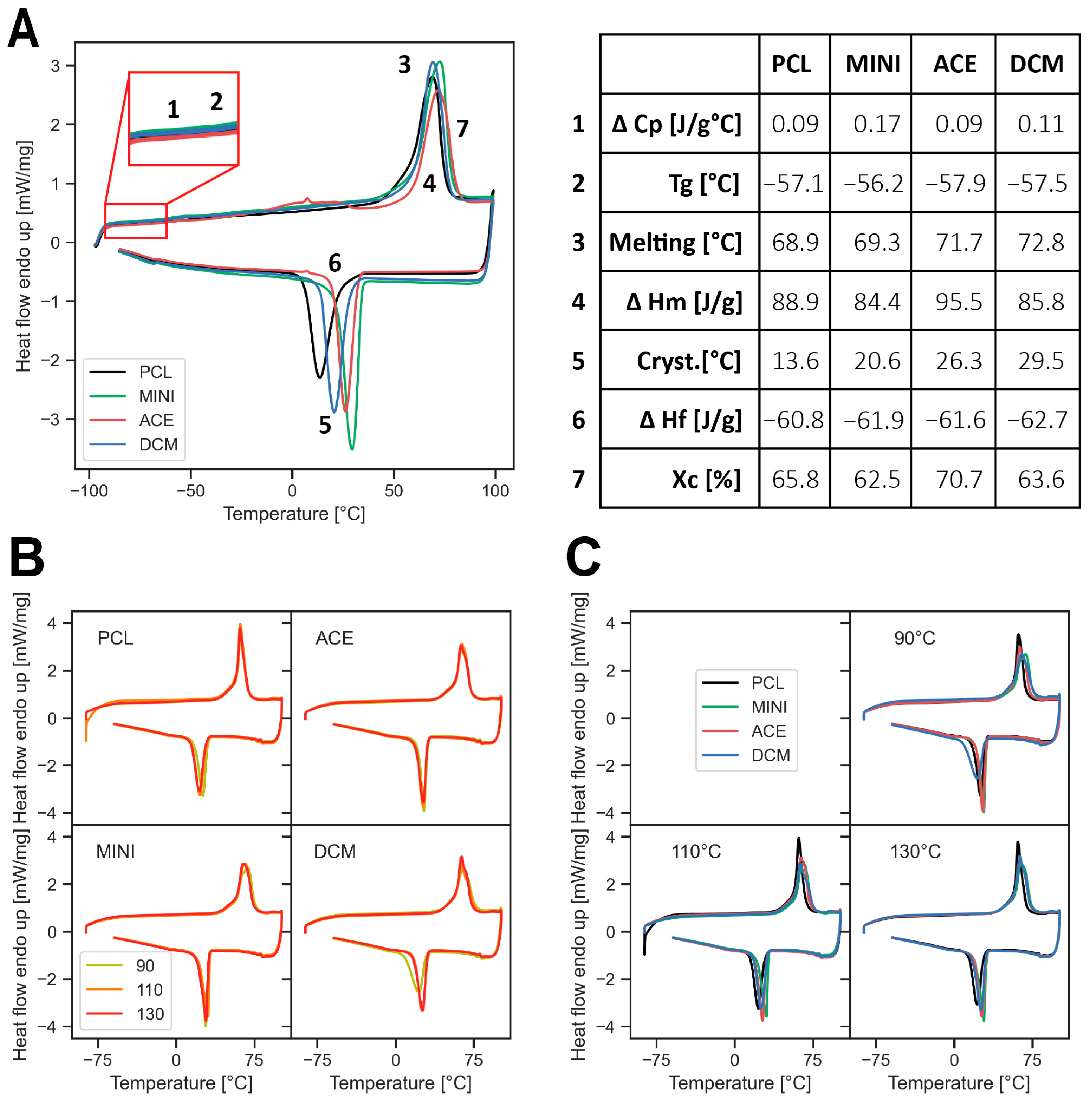
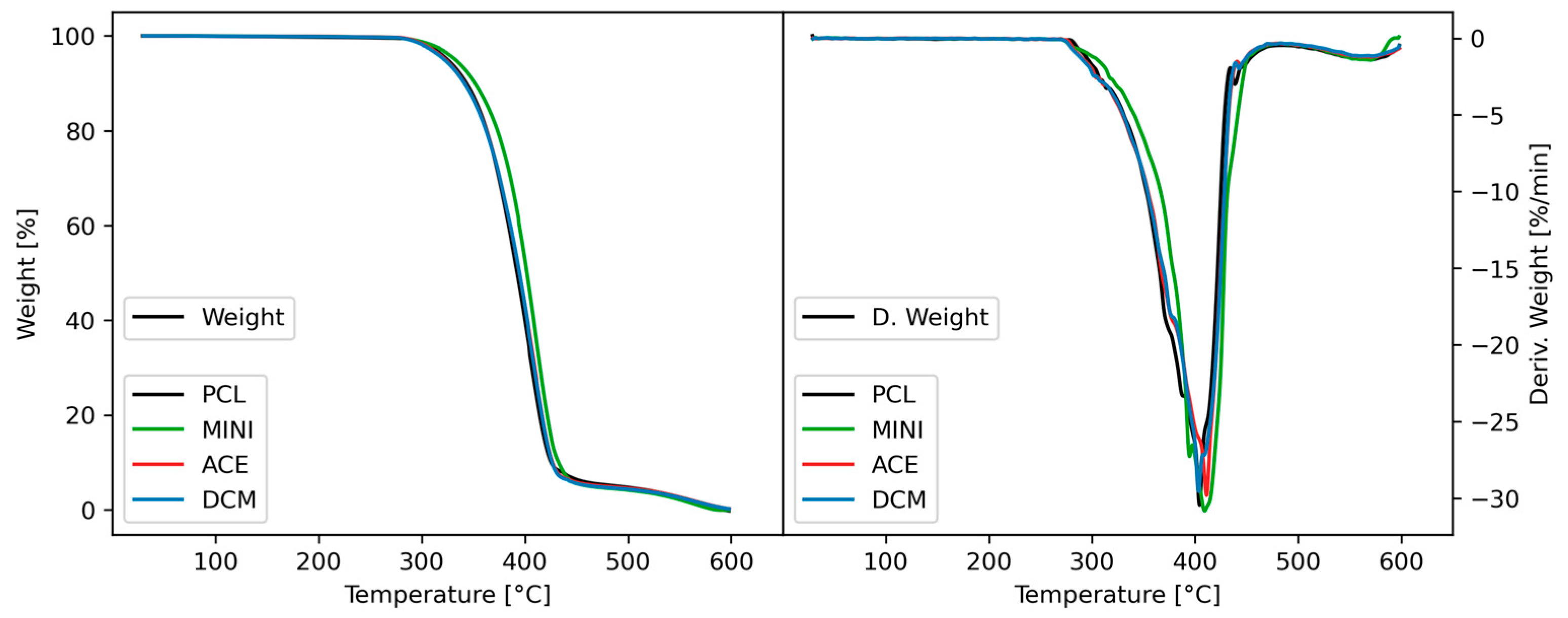
3.1. Thermal Properties
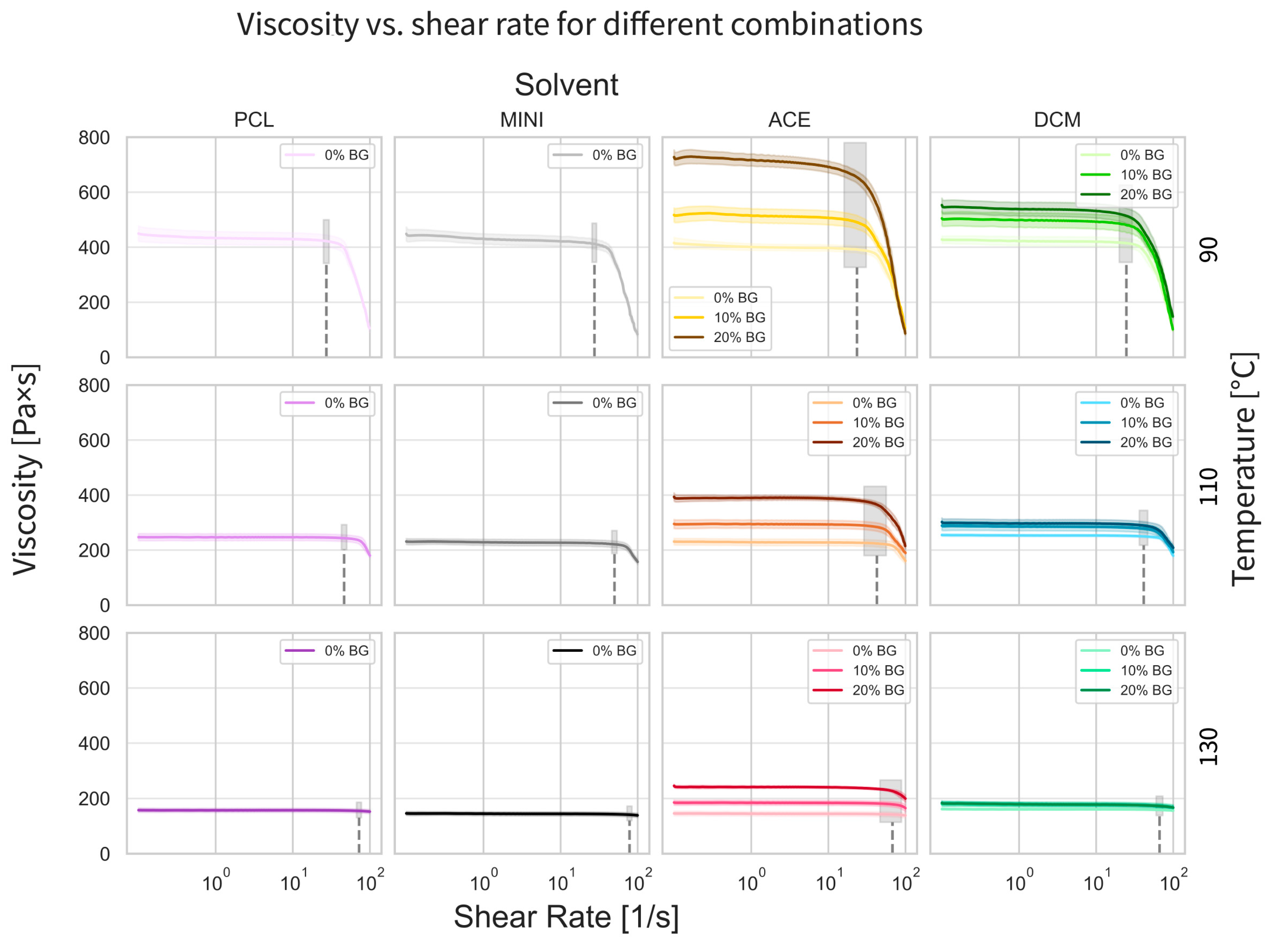
3.2. Rheological Properties
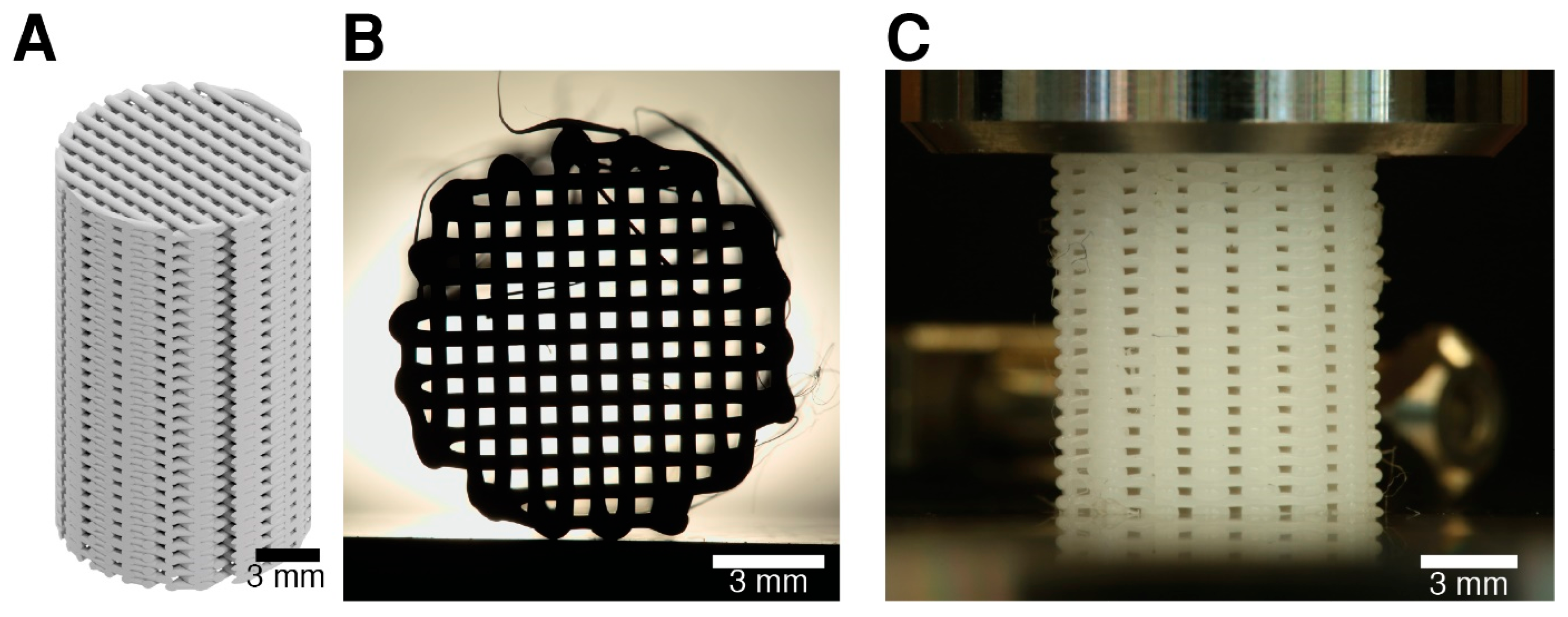
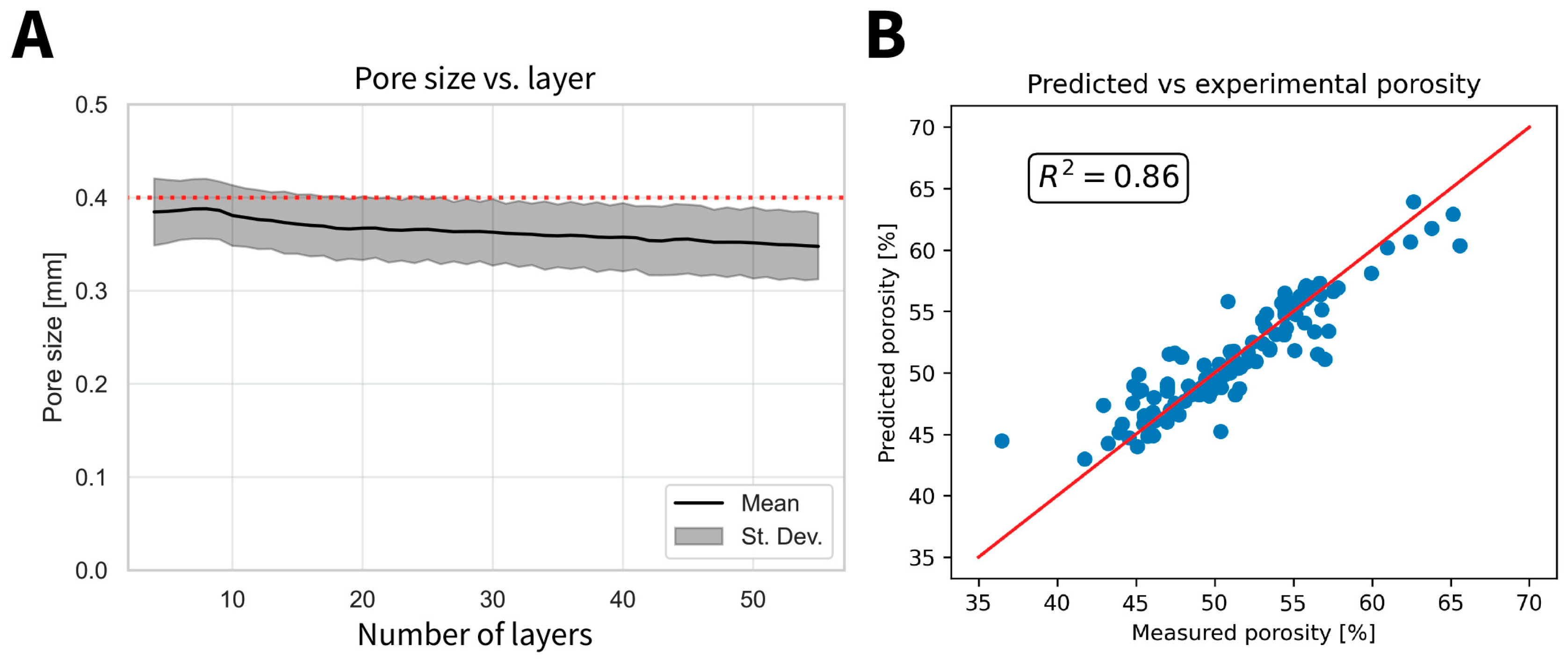
3.3. Scaffold Microstructural Characterization
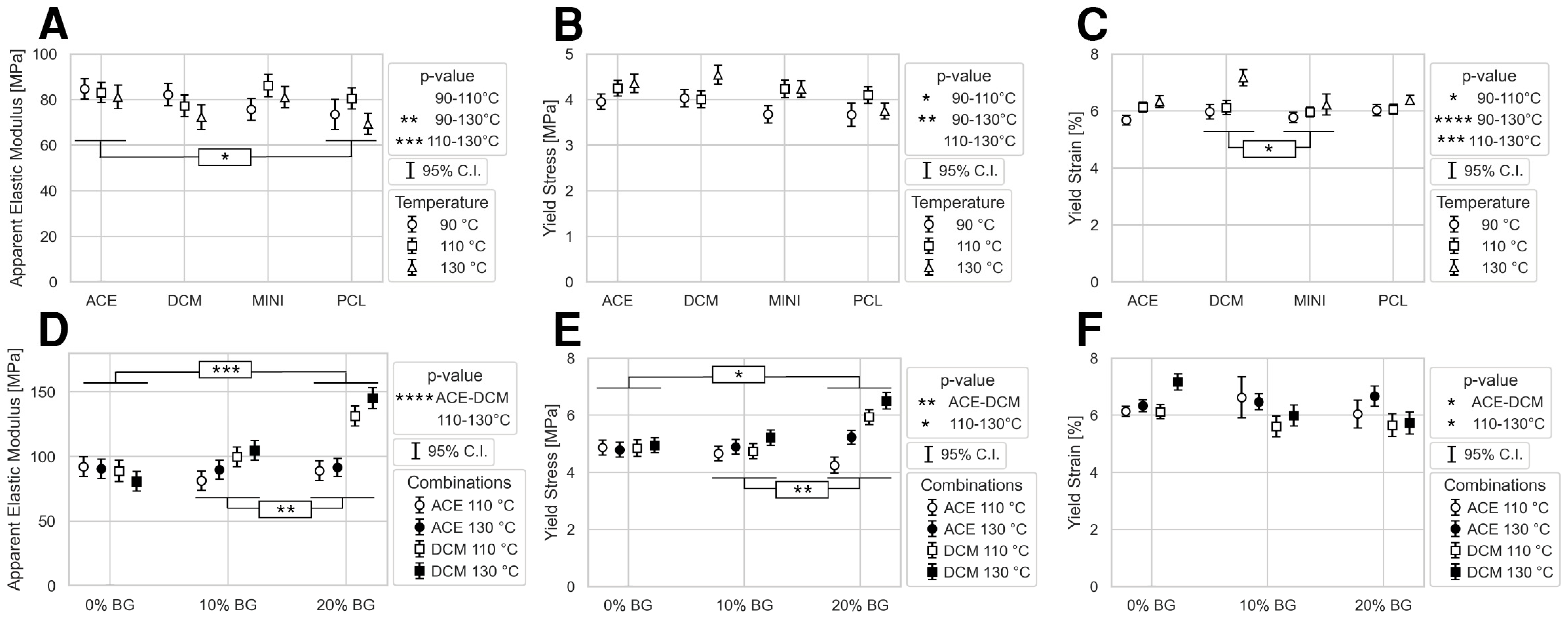
3.4. Scaffold Mechanical Properties
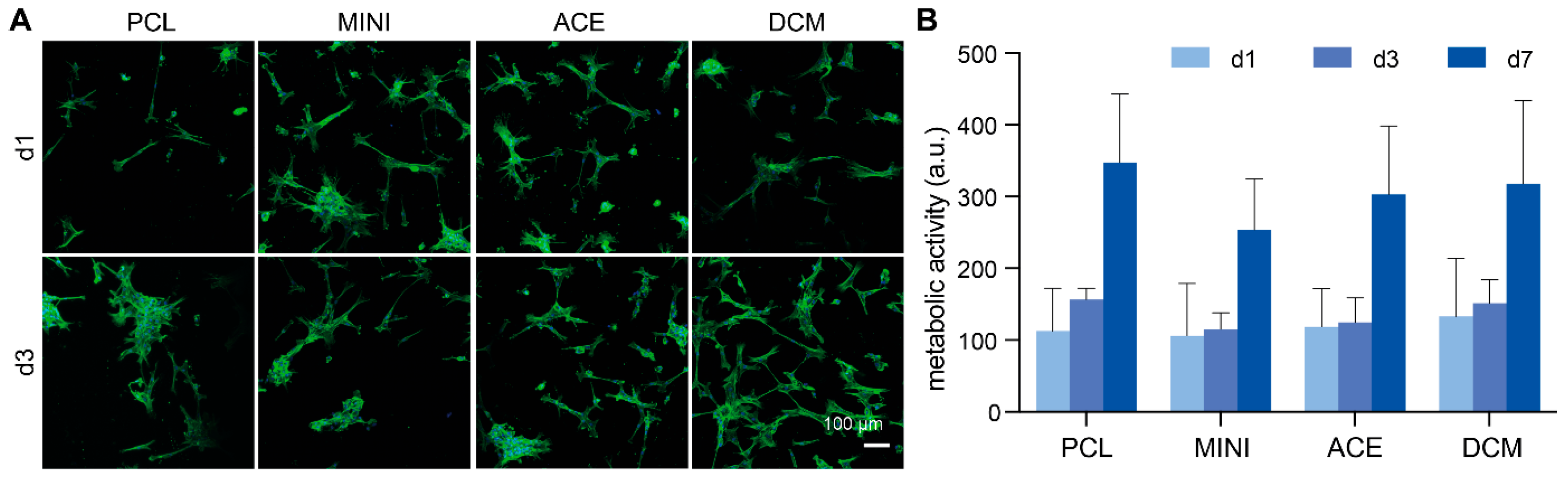
3.5. Scaffold Biological Properties
4. Discussion
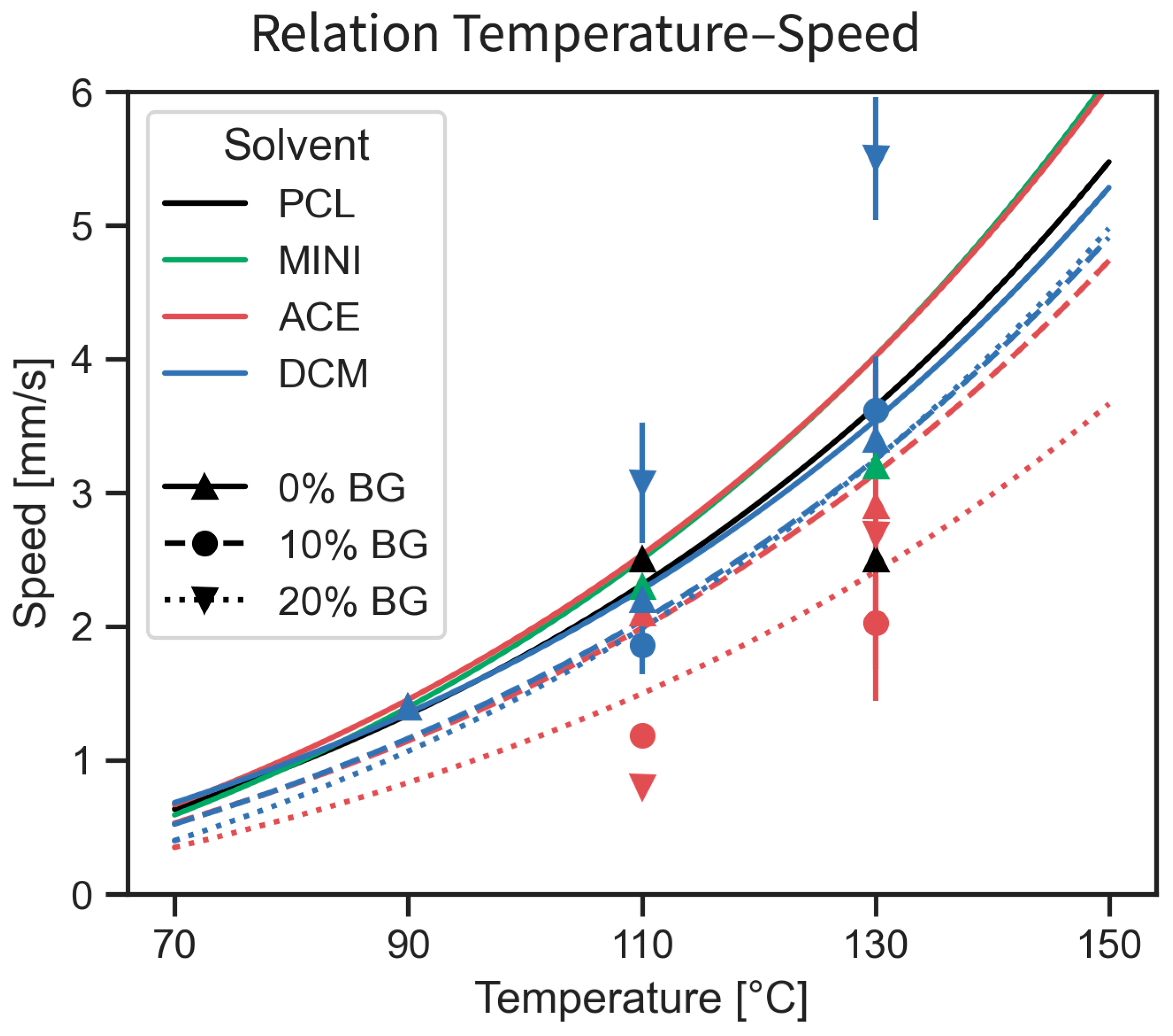
4.1. Printability
4.2. Thermal, Mechanical, and Biological Properties
4.3. Limitations
5. Conclusions
Supplementary Materials
Author Contributions
Funding
Data Availability Statement
Acknowledgments
Conflicts of Interest
References
- Samaro, A.; Janssens, P.; Vanhoorne, V.; Van Renterghem, J.; Eeckhout, M.; Cardon, L.; De Beer, T.; Vervaet, C. Screening of pharmaceutical polymers for extrusion-Based Additive Manufacturing of patient-tailored tablets. Int. J. Pharm. 2020, 586, 119591. [Google Scholar] [CrossRef] [PubMed]
- Spoerk, M.; Arbeiter, F.; Koutsamanis, I.; Cajner, H.; Katschnig, M.; Eder, S. Personalised urethra pessaries prepared by material extrusion-based additive manufacturing. Int. J. Pharm. 2021, 608, 121112. [Google Scholar] [CrossRef]
- Jin, M.; Neuber, C.; Schmidt, H.W. Tailoring polypropylene for extrusion-based additive manufacturing. Addit. Manuf. 2020, 33, 101101. [Google Scholar] [CrossRef]
- Hausmann, M.K.; Rühs, P.A.; Siqueira, G.; Läuger, J.; Libanori, R.; Zimmermann, T.; Studart, A.R. Dynamics of Cellulose Nanocrystal Alignment during 3D Printing. ACS Nano 2018, 12, 6926–6937. [Google Scholar] [CrossRef] [PubMed]
- Tappa, K.; Jammalamadaka, U. Novel biomaterials used in medical 3D printing techniques. J. Funct. Biomater. 2018, 9, 17. [Google Scholar] [CrossRef]
- Pae, H.C.; Kang, J.H.; Cha, J.K.; Lee, J.S.; Paik, J.W.; Jung, U.W.; Kim, B.H.; Choi, S.H. 3D-printed polycaprolactone scaffold mixed with β-tricalcium phosphate as a bone regenerative material in rabbit calvarial defects. J. Biomed. Mater. Res. Part. B Appl. Biomater. 2019, 107, 1254–1263. [Google Scholar] [CrossRef]
- Williams, J.M.; Adewunmi, A.; Schek, R.M.; Flanagan, C.L.; Krebsbach, P.H.; Feinberg, S.E.; Hollister, S.J.; Das, S. Bone tissue engineering using polycaprolactone scaffolds fabricated via selective laser sintering. Biomaterials 2005, 26, 4817–4827. [Google Scholar] [CrossRef] [PubMed]
- Garcia-Giralt, N.; Izquierdo, R.; Nogués, X.; Perez-Olmedilla, M.; Benito, P.; Gómez-Ribelles, J.L.; Checa, M.A.; Suay, J.; Caceres, E.; Monllau, J.C. A porous PCL scaffold promotes the human chondrocytes redifferentiation and hyaline-specific extracellular matrix protein synthesis. J. Biomed. Mater. Res.-Part. A 2008, 85, 1082–1089. [Google Scholar] [CrossRef]
- Ma, Z.; Xie, J.; Shan, X.Z.; Zhang, J.; Wang, Q. High solid content 45S5 Bioglass®-based scaffolds using stereolithographic ceramic manufacturing: Process, structural and mechanical properties. J. Mech. Sci. Technol. 2021, 35, 823–832. [Google Scholar] [CrossRef]
- Kargozar, S.; Baino, F.; Hamzehlou, S.; Hill, R.G.; Mozafari, M. Bioactive Glasses: Sprouting Angiogenesis in Tissue Engineering. Trends Biotechnol. 2018, 36, 430–444. [Google Scholar] [CrossRef]
- Zeimaran, E.; Pourshahrestani, S.; Fathi, A.; Razak, N.A.b.A.; Kadri, N.A.; Sheikhi, A.; Baino, F. Advances in bioactive glass-containing injectable hydrogel biomaterials for tissue regeneration. Acta Biomater. 2021, 136, 1–36. [Google Scholar] [CrossRef] [PubMed]
- Soni, R.; Vijay Kumar, N.; Chameettachal, S.; Pati, F.; Rath, S.N. Synthesis and optimization of PCL-bioactive glass composite scaffold for bone tissue engineering. Mater. Today Proc. 2019, 15, 294–299. [Google Scholar] [CrossRef]
- Daskalakis, E.; Huang, B.; Vyas, C.; Acar, A.A.; Fallah, A.; Cooper, G.; Weightman, A.; Koc, B.; Blunn, G.; Bartolo, P. Novel 3D Bioglass Scaffolds for Bone Tissue Regeneration. Polymers 2022, 14, 445. [Google Scholar] [CrossRef]
- Dukle, A.; Murugan, D.; Nathanael, A.J.; Rangasamy, L.; Oh, T.H. Can 3D-Printed Bioactive Glasses Be the Future of Bone Tissue Engineering? Polymers 2022, 14, 1627. [Google Scholar] [CrossRef]
- Jacobsen, S.; Fritz, H.G. Plasticizing polylactide?the effect of different plasticizers on the mechanical properties. Polym. Eng. Sci. 1999, 39, 1303–1310. [Google Scholar] [CrossRef]
- Chaos, A.; Sangroniz, A.; Gonzalez, A.; Iriarte, M.; Sarasua, J.R.; del Río, J.; Etxeberria, A. Tributyl citrate as an effective plasticizer for biodegradable polymers: Effect of plasticizer on free volume and transport and mechanical properties. Polym. Int. 2019, 68, 125–133. [Google Scholar] [CrossRef]
- Joshi, D.R.; Adhikari, N. An Overview on Common Organic Solvents and Their Toxicity. J. Pharm. Res. Int. 2019, 28, 1–18. [Google Scholar] [CrossRef]
- Baier, R.V.; Contreras Raggio, J.I.; Giovanetti, C.M.; Palza, H.; Burda, I.; Terrasi, G.; Weisse, B.; De Freitas, G.S.; Nystrom, G.; Vivanco, J.F.; et al. Shape fidelity, mechanical and biological performance of 3D printed polycaprolactone-bioactive glass composite scaffolds. Biomater. Adv. 2022, 134, 112540. [Google Scholar] [CrossRef] [PubMed]
- Xu, X.; Yang, J.; Jonhson, W.; Wang, Y.; Suwardi, A.; Ding, J.; Guan, C.; Zhang, D. Additive manufacturing solidification methodologies for ink formulation. Addit. Manuf. 2022, 56, 102939. [Google Scholar] [CrossRef]
- Palza Cordero, H.; Castro Cid, R.; Diaz Dosque, M.; Cabello Ibacache, R.; Palma Fluxá, P. Li-doped bioglass® 45S5 for potential treatment of prevalent oral diseases. J. Dent. 2021, 105, 103575. [Google Scholar] [CrossRef]
- Bejarano, J.; Caviedes, P.; Palza, H. Sol-gel synthesis and in vitro bioactivity of copper and zinc-doped silicate bioactive glasses and glass-ceramics. Biomed. Mater. 2015, 10, 25001. [Google Scholar] [CrossRef] [PubMed]
- Nagata, M.; Sato, Y. Biodegradable elastic photocured polyesters based on adipic acid, 4-hydroxycinnamic acid and poly(ε-caprolactone) diols. Polymer 2004, 45, 87–93. [Google Scholar] [CrossRef]
- Siqueira, G.; Libanori, R.; Hausmann, M.K.; Gladman, A.S.; Kokkinis, D.; Neels, A.; Tingaut, P.; Zimmermann, T.; Lewis, J.A.; Studart, A.R. Cellulose Nanocrystal Inks for 3D Printing of Textured Cellular Architectures. Adv. Funct. Mater. 2017, 27, 1604619. [Google Scholar] [CrossRef]
- Martinez-Diaz, S.; Garcia-Giralt, N.; Lebourg, M.; Gómez-Tejedor, J.A.; Vila, G.; Caceres, E.; Benito, P.; Pradas, M.M.; Nogues, X.; Ribelles, J.L.; et al. In Vivo evaluation of 3-dimensional polycaprolactone scaffolds for cartilage repair in rabbits. Am. J. Sports Med. 2010, 38, 509–519. [Google Scholar] [CrossRef]
- Izquierdo, R.; Garcia-Giralt, N.; Rodriguez, M.T.; Cáceres, E.; García, S.J.; Gómez Ribelles, J.L.; Monleón, M.; Monllau, J.C.; Suay, J. Biodegradable PCL scaffolds with an interconnected spherical pore network for tissue engineering. J. Biomed. Mater. Res. Part. A 2008, 85A, 25–35. [Google Scholar] [CrossRef]
- ASTM D695−15; ASTM. Standard Test Method for Compressive Properties of Rigid Plastics 1 Standard Test Method for Compressive Properties of Rigid Plastics. American Society for Testing and Materials: West Conshohocken, PA, USA, 2015; pp. 12959–19428.
- Ho, S.T.; Hutmacher, D.W. A comparison of micro CT with other techniques used in the characterization of scaffolds. Biomaterials 2006, 27, 1362–1376. [Google Scholar] [CrossRef]
- Ashby, M.; Shercliff, H.; Cebon, D. Materials: Engineering, science, processing and design. Mater. Today 2010, 13, 67. [Google Scholar]
- Contreras Raggio, J.I.; Arancibia, C.T.; Millán, C.; Ploeg, H.L.; Aiyangar, A.; Vivanco, J.F. Height-to-Diameter Ratio and Porosity Strongly Influence Bulk Compressive Mechanical Properties of 3D-Printed Polymer Scaffolds. Polymers 2022, 14, 5017. [Google Scholar] [CrossRef]
- Leppink, J. Analysis of Covariance (ANCOVA) vs. Moderated Regression (MODREG). Why Interact. Matters 2018, 4, 225–232. [Google Scholar]
- Chae, D.W.; Nam, Y.; An, S.G.; Cho, C.G.; Lee, E.J.; Kim, B.C. Effects of molecular architecture on the rheological and physical properties of polycaprolactone. Korea Aust. Rheol. J. 2017, 29, 129–135. [Google Scholar] [CrossRef]
- Arraiza, A.L.; Sarasua, J.R.; Verdu, J.; Colin, X. Rheological behavior and modeling of thermal degradation of poly(ε-caprolactone) and poly(L-lactide). Int. Polym. Process. 2007, 22, 389–394. [Google Scholar] [CrossRef]
- Brillinger, M.; Pendl, K.A. Non newtonian material behaviour in extrusion based 3D printing: Investigation of critical process parameters. Proc. World Congr. Mech. Chem. Mater. Eng. 2020, 1–10. [Google Scholar]
- Schwab, A.; Levato, R.; D’Este, M.; Piluso, S.; Eglin, D.; Malda, J. Printability and Shape Fidelity of Bioinks in 3D Bioprinting. Chem. Rev. 2020, 120, 11028–11055. [Google Scholar] [CrossRef]
- O’Brien, F.J. Biomaterials & scaffolds for tissue engineering. Mater. Today 2011, 14, 88–95. [Google Scholar]
- Karageorgiou, V.; Kaplan, D. Porosity of 3D biomaterial scaffolds and osteogenesis. Biomaterials 2005, 26, 5474–5491. [Google Scholar] [CrossRef]
- Myakinin, A.; Turlybekuly, A.; Pogrebnjak, A.; Mirek, A.; Bechelany, M.; Liubchak, I.; Oleshko, O.; Husak, Y.; Korniienko, V.; Leśniak-Ziółkowska, K.; et al. In vitro evaluation of electrochemically bioactivated Ti6Al4V 3D porous scaffolds. Mater. Sci. Eng. C 2021, 121, 111870. [Google Scholar] [CrossRef]
- Cea, K.; Donoso, M.; Martinez, G.; Alegria, L. Evaluation of Parameters in PLA and PCL Scaffolds to be Used in Cartilaginous Tissues. Rev. Mex. Ing. Biomédica 2021, 42, 149–159. [Google Scholar]
- Spoerk, M.; Gonzalez-Gutierrez, J.; Sapkota, J.; Schuschnigg, S.; Holzer, C. Effect of the printing bed temperature on the adhesion of parts produced by fused filament fabrication. Plast. Rubber Compos. 2018, 47, 17–24. [Google Scholar] [CrossRef]
- Qin, X.; Wu, D. Effect of different solvents on poly(caprolactone) (PCL) electrospun nonwoven membranes. J. Therm. Anal. Calorim. 2012, 107, 1007–1013. [Google Scholar] [CrossRef]
- Gharibshahian, M.; Salehi, M.; Beheshtizadeh, N.; Kamalabadi-Farahani, M.; Atashi, A.; Nourbakhsh, M.-S.; Alizadeh, M. Recent advances on 3D-printed PCL-based composite scaffolds for bone tissue engineering. Front. Bioeng. Biotechnol. 2023, 11, 1168504. [Google Scholar] [CrossRef]
- Wiesli, M.G.; Huber, M.W.; Weisse, B.; Zboray, R.; Kiderlen, S.; González-Vázquez, A.; Maniura-Weber, K.; Rottmar, M.; Lackington, W.A. Immunomodulation Using BMP-7 and IL-10 to Enhance the Mineralization Capacity of Bone Progenitor Cells in a Fracture Hematoma-Like Environment. Adv. Heal. Mater. 2025, 14, e2400077. [Google Scholar] [CrossRef] [PubMed]
- Shotorbani, B.B.; Alizadeh, E.; Salehi, R.; Barzegar, A. Adhesion of mesenchymal stem cells to biomimetic polymers: A review. Mater. Sci. Eng. C Mater. Biol. Appl. 2017, 71, 1192–1200. [Google Scholar] [CrossRef] [PubMed]
- Rajzer, I.; Kurowska, A.; Frankova, J.; Sklenářová, R.; Nikodem, A.; Dziadek, M.; Jabłoński, A.; Janusz, J.; Szczygieł, P.; Ziąbka, M. 3D-Printed Polycaprolactone Implants Modified with Bioglass and Zn-Doped Bioglass. Materials 2023, 16, 1061. [Google Scholar] [CrossRef] [PubMed]

| Compounding | Extrusion Temperature | ||||
|---|---|---|---|---|---|
| Acronym | Solvent | 90 °C | 110 °C | 130 °C | |
| PCL (control) | None | 0% | 0% | 0% | BG% Content |
| PCL-Mini | Mechanical compounding | 0% | 0% | 0% | |
| PCL-DCM | Dichloromethane | 0% | 0% 10% 20% | 0% 10% 20% | |
| PCL-Ace | Acetone | 0% | 0% 10% 20% | 0% 10% 20% | |
Disclaimer/Publisher’s Note: The statements, opinions and data contained in all publications are solely those of the individual author(s) and contributor(s) and not of MDPI and/or the editor(s). MDPI and/or the editor(s) disclaim responsibility for any injury to people or property resulting from any ideas, methods, instructions or products referred to in the content. |
© 2025 by the authors. Licensee MDPI, Basel, Switzerland. This article is an open access article distributed under the terms and conditions of the Creative Commons Attribution (CC BY) license (https://creativecommons.org/licenses/by/4.0/).
Share and Cite
Contreras Raggio, J.I.; Pardo, M.; Núñez, P.; Millán, C.; Siqueira, G.; Palza, H.; Vivanco, J.F.; Aiyangar, A.K. Effect of Processing Parameters on the Printability and Mechano-Biological Properties of Polycaprolactone–Bioactive Glass Composites for 3D-Printed Scaffold Fabrication. Polymers 2025, 17, 1554. https://doi.org/10.3390/polym17111554
Contreras Raggio JI, Pardo M, Núñez P, Millán C, Siqueira G, Palza H, Vivanco JF, Aiyangar AK. Effect of Processing Parameters on the Printability and Mechano-Biological Properties of Polycaprolactone–Bioactive Glass Composites for 3D-Printed Scaffold Fabrication. Polymers. 2025; 17(11):1554. https://doi.org/10.3390/polym17111554
Chicago/Turabian StyleContreras Raggio, José I., Miguel Pardo, Pablo Núñez, Carola Millán, Gilberto Siqueira, Humberto Palza, Juan F. Vivanco, and Ameet K. Aiyangar. 2025. "Effect of Processing Parameters on the Printability and Mechano-Biological Properties of Polycaprolactone–Bioactive Glass Composites for 3D-Printed Scaffold Fabrication" Polymers 17, no. 11: 1554. https://doi.org/10.3390/polym17111554
APA StyleContreras Raggio, J. I., Pardo, M., Núñez, P., Millán, C., Siqueira, G., Palza, H., Vivanco, J. F., & Aiyangar, A. K. (2025). Effect of Processing Parameters on the Printability and Mechano-Biological Properties of Polycaprolactone–Bioactive Glass Composites for 3D-Printed Scaffold Fabrication. Polymers, 17(11), 1554. https://doi.org/10.3390/polym17111554