

Design of a Superlubricity System Using Polyimide Film Surface-Modified Poly-Ether-Ether-Ketone

Abstract
1. Introduction
2. Experimental Section
2.1. Experimental Materials
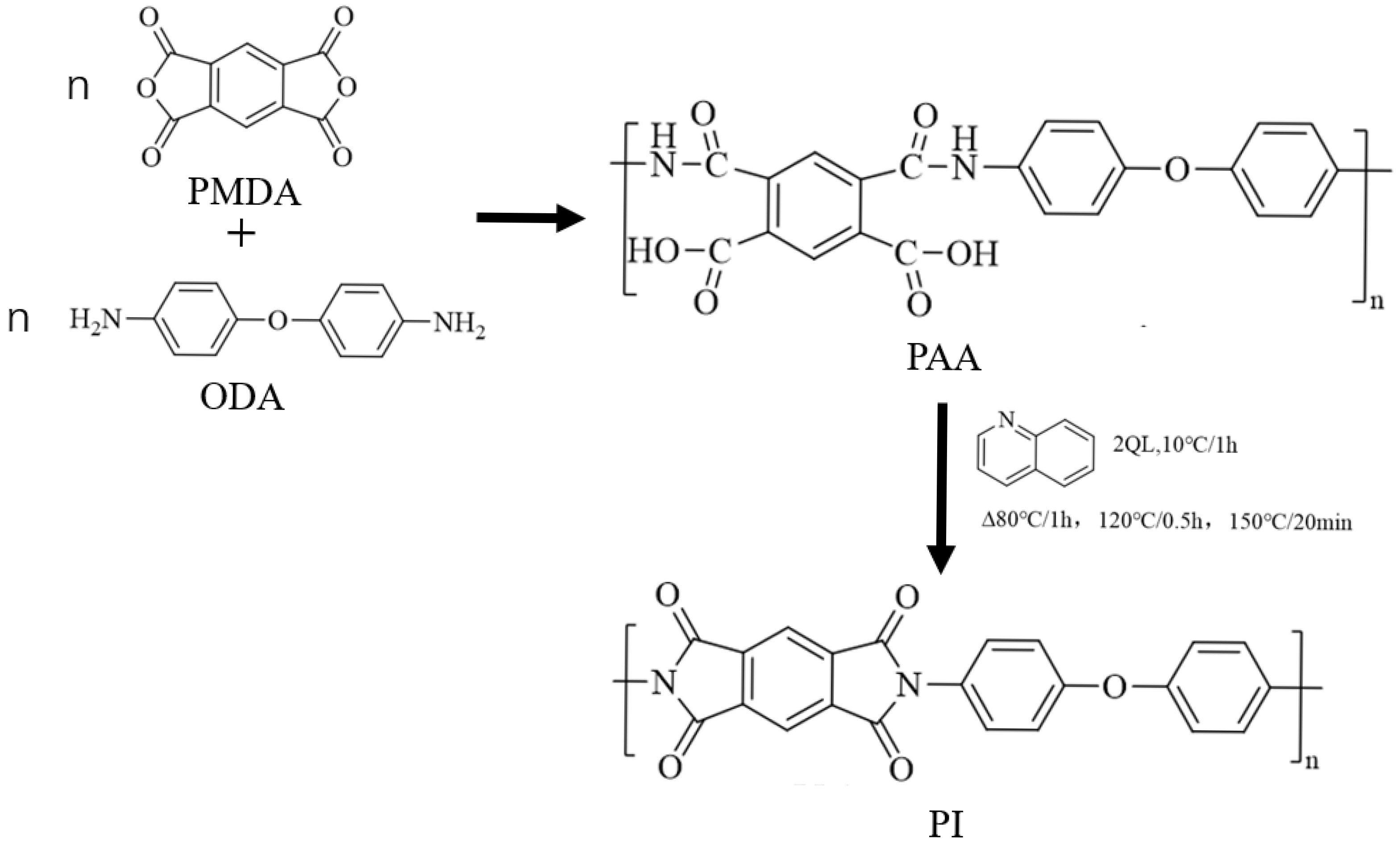
2.2. Preparation of Modified Materials
2.3. Tribological Testing
2.3.1. Preparation of Friction Pairs
2.3.2. Friction Testing
Selection of Different Plates and Lubricants for Testing
Different Speed Tests
Different Load Tests
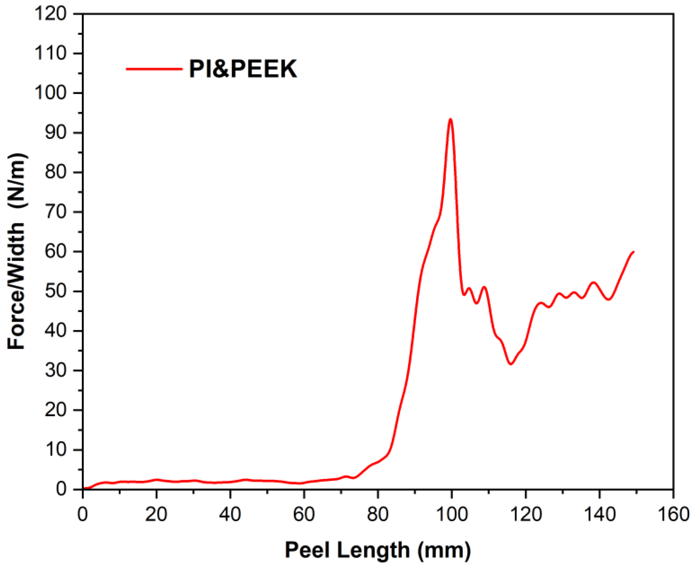
2.4. Peel Strength Test Method
2.5. Surface Analysis Methods
3. Results and Discussion
3.1. Micro-Friction Experiments
3.1.1. Speed Variation Tests
Load of 5 N
Load of 25 N
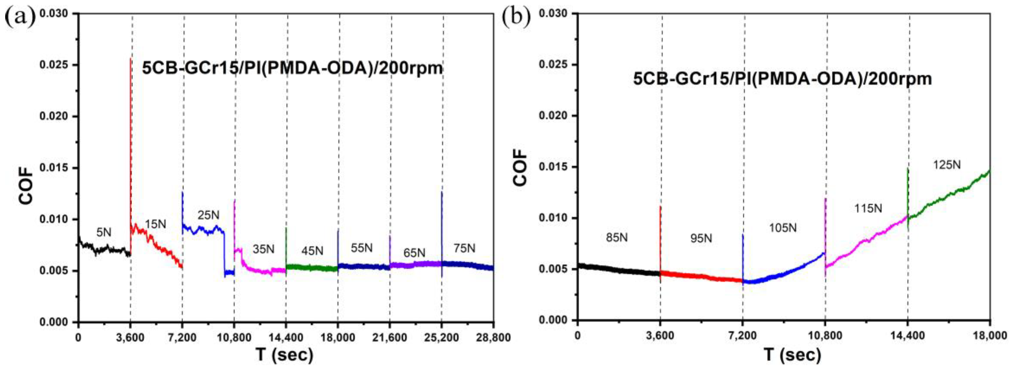
3.1.2. Load Variation Tests
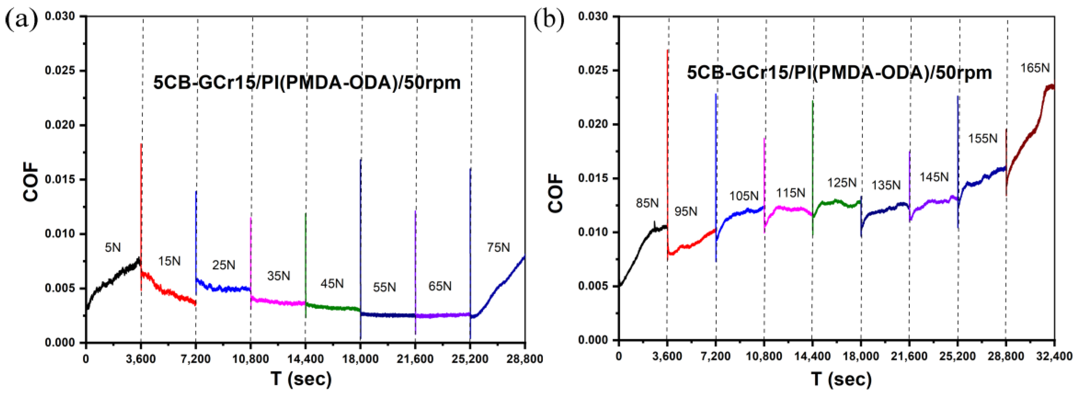
Fixed Speed of 50 rpm
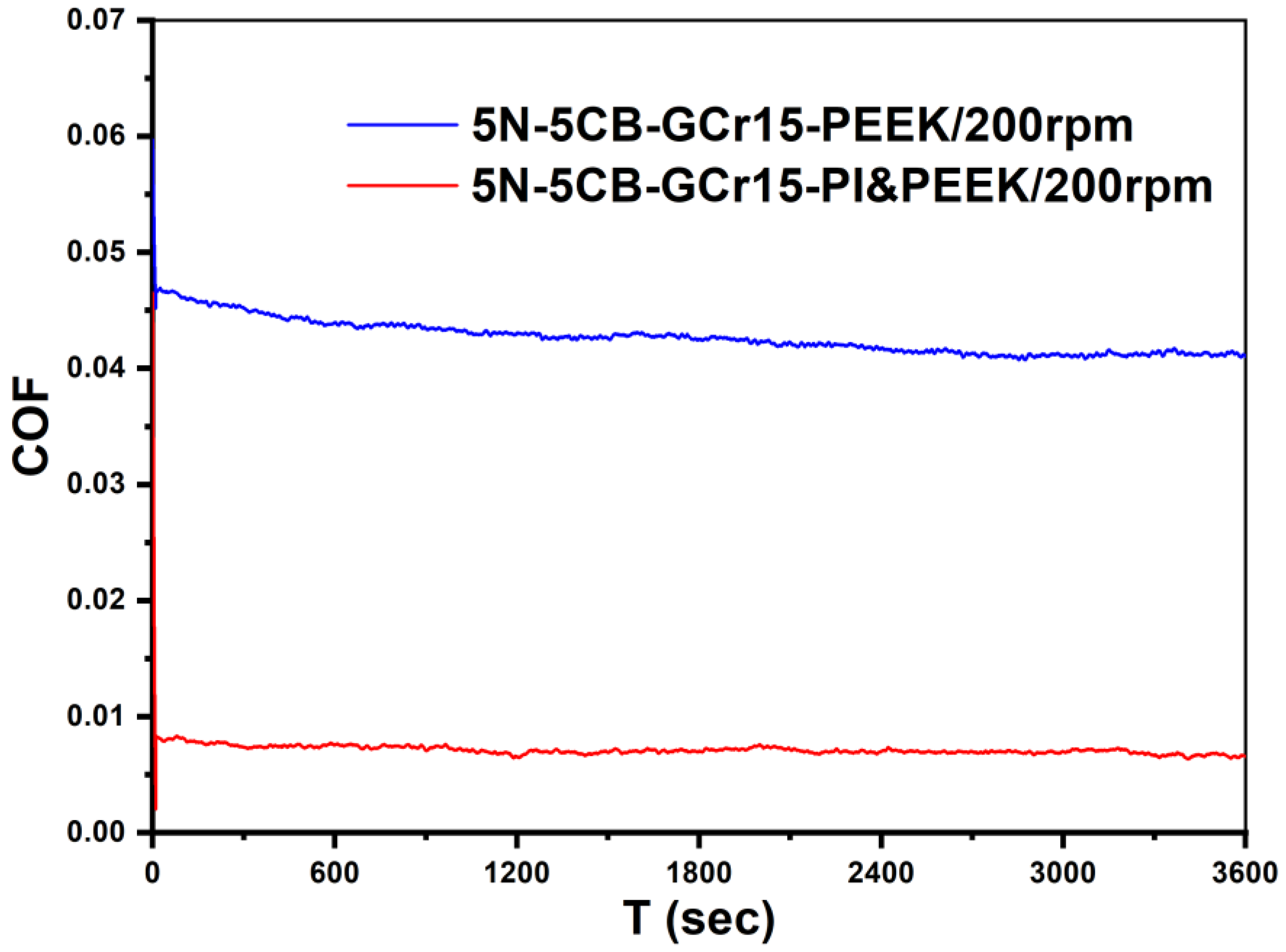
Fixed Speed of 200 rpm
3.2. Peel Strength Test of PI&PEEK
3.3. Characterization of PI Film Samples
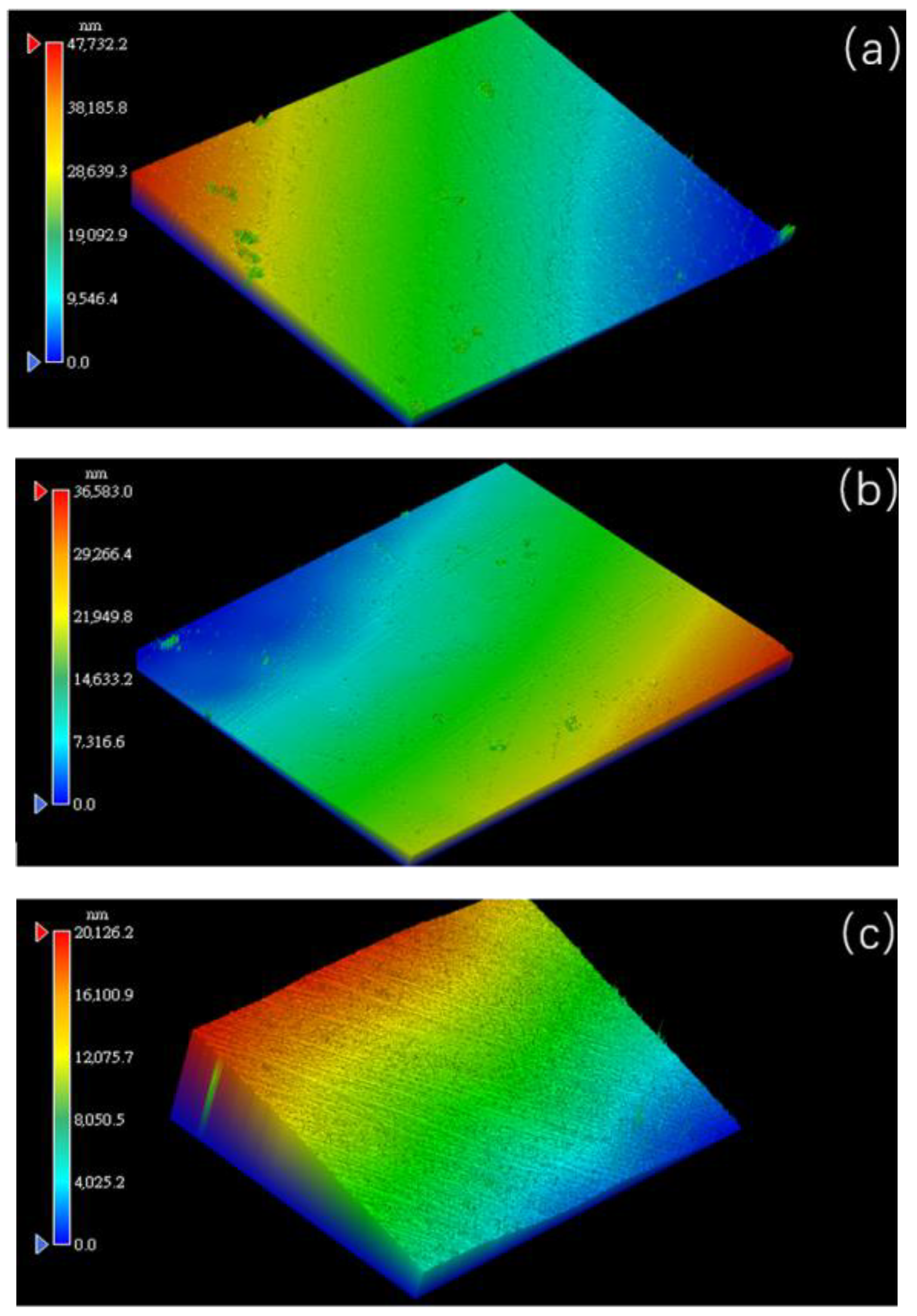
3.3.1. White Light Interferometry
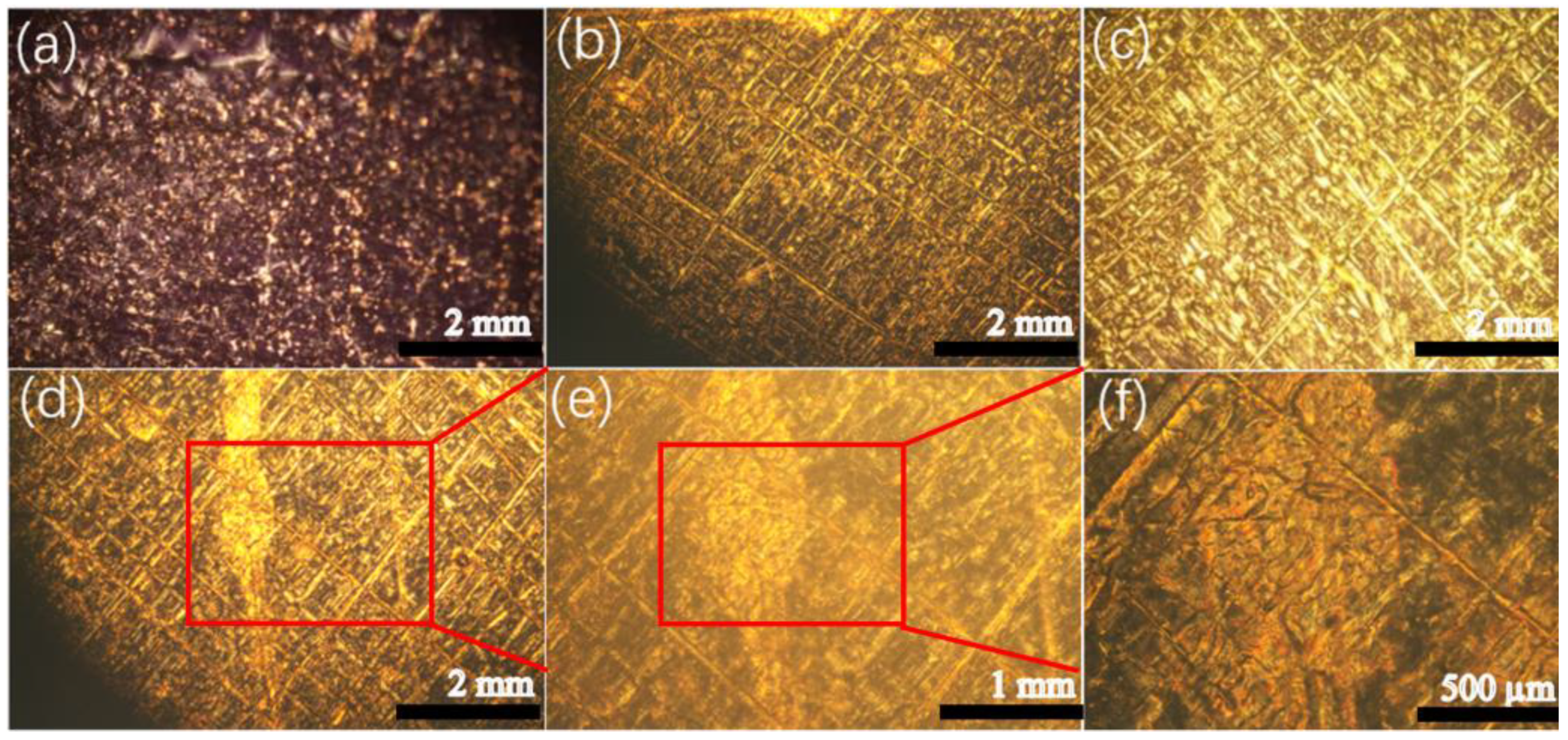
3.3.2. Polarized Light Microscopy
3.3.3. Raman Spectroscopy
4. Conclusions
Author Contributions
Funding
Data Availability Statement
Conflicts of Interest
References
- Perry, S.S.; Tysoe, W.T. Frontiers of fundamental tribological research. Tribol. Lett. 2005, 19, 151–161. [Google Scholar] [CrossRef]
- Holmberg, K.; Erdemir, A. Influence of tribology on global energy consumption, costs and emissions. Friction 2017, 5, 263–284. [Google Scholar] [CrossRef]
- Woydt, M. The importance of tribology for reducing CO2 emissions and for sustainability. Wear 2021, 474–475, 203768. [Google Scholar] [CrossRef]
- Zheng, Z.; Guo, Z.; Liu, W.; Luo, J. Low friction of superslippery and superlubricity: A review. Friction 2023, 11, 1121–1137. [Google Scholar] [CrossRef]
- Hirano, M.; Shinjo, K. Atomistic locking and friction. Phys. Rev. B 1990, 41, 11837–11851. [Google Scholar] [CrossRef]
- Hirano, M.; Shinjo, K.; Kaneko, R.; Murata, Y. Anisotropy of frictional forces in muscovite mica. Phys. Rev. Lett. 1991, 67, 2642–2645. [Google Scholar] [CrossRef] [PubMed]
- Martin, J.M.; Donnet, C.; Le Mogne, T.; Epicier, T. Superlubricity of molybdenum disulphide. Phys. Rev. B 1993, 48, 10583–10586. [Google Scholar] [CrossRef]
- Li, Q.; Newberg, J.T.; Walter, E.C.; Hemminger, J.C.; Penner, R.M. Polycrystalline Molybdenum Disulfide (2H−MoS2) Nano- and Microribbons by Electrochemical/Chemical Synthesis. Nano Lett. 2004, 4, 277–281. [Google Scholar] [CrossRef]
- Sano, N.; Wang, H.; Chhowalla, M.; Alexandrou, I.; Amaratunga, G.A.J.; Naito, M.; Kanki, T. Fabrication of inorganic molybdenum disulfide fullerenes by arc in water. Chem. Phys. Lett. 2003, 368, 331–337. [Google Scholar] [CrossRef]
- Jiménez, I.; Jankowski, A.F.; Terminello, L.J.; Sutherland, D.G.J.; Carlisle, J.A.; Doll, G.L.; Tong, W.M.; Shuh, D.K.; Himpsel, F.J. Core-level photoabsorption study of defects and metastable bonding configurations in boron nitride. Phys. Rev. B 1997, 55, 12025–12037. [Google Scholar] [CrossRef]
- Cumings, J.; Zettl, A. Low-Friction Nanoscale Linear Bearing Realized from Multiwall Carbon Nanotubes. Science 2000, 289, 602–604. [Google Scholar] [CrossRef] [PubMed]
- Hirano, M.; Shinjo, K.; Kaneko, R.; Murata, Y. Observation of Superlubricity by Scanning Tunneling Microscopy. Phys. Rev. Lett. 1997, 78, 1448–1451. [Google Scholar] [CrossRef]
- Dienwiebel, M.; Verhoeven, G.S.; Pradeep, N.; Frenken, J.W.M.; Heimberg, J.A.; Zandbergen, H.W. Superlubricity of Graphite. Phys. Rev. Lett. 2004, 92, 126101. [Google Scholar] [CrossRef]
- Hod, O.; Meyer, E.; Zheng, Q.; Urbakh, M. Structural superlubricity and ultralow friction across the length scales. Nature 2018, 563, 485–492. [Google Scholar] [CrossRef]
- Song, Y.; Mandelli, D.; Hod, O.; Urbakh, M.; Ma, M.; Zheng, Q. Robust microscale superlubricity in graphite/hexagonal boron nitride layered heterojunctions. Nat. Mater. 2018, 17, 894–899. [Google Scholar] [CrossRef]
- Qu, C.; Wang, K.; Wang, J.; Gongyang, Y.; Carpick, R.W.; Urbakh, M.; Zheng, Q. Origin of Friction in Superlubric Graphite Contacts. Phys. Rev. Lett. 2020, 125, 126102. [Google Scholar] [CrossRef]
- Song, Y.; Qu, C.; Ma, M.; Zheng, Q. Structural Superlubricity Based on Crystalline Materials. Small 2020, 16, e1903018. [Google Scholar] [CrossRef]
- Huang, X.; Li, T.; Wang, J.; Xia, K.; Tan, Z.; Peng, D.; Xiang, X.; Liu, B.; Ma, M.; Zheng, Q. Robust microscale structural superlubricity between graphite and nanostructured surface. Nat. Commun. 2023, 14, 2931. [Google Scholar] [CrossRef] [PubMed]
- Huang, X.; Xiang, X.; Li, C.; Nie, J.; Shao, Y.; Xu, Z.; Zheng, Q. Electrostatic in-plane structural superlubric actuator. Nat. Commun. 2025, 16, 493. [Google Scholar] [CrossRef]
- Ge, X.; Li, J.; Zhang, C.; Wang, Z.; Luo, J. Superlubricity of 1-Ethyl-3-methylimidazolium trifluoromethanesulfonate Ionic Liquid Induced by Tribochemical Reactions. Langmuir 2018, 34, 5245–5252. [Google Scholar] [CrossRef]
- Lebedeva, O.; Kultin, D.; Kustov, L. Polymeric ionic liquids: Here, there and everywhere. Eur. Polym. J. 2024, 203, 112657. [Google Scholar] [CrossRef]
- Liu, M.; Ni, J.; Zhang, C.; Wang, R.; Cheng, Q.; Liang, W.; Liu, Z. The Application of Ionic Liquids in the Lubrication Field: Their Design, Mechanisms, and Behaviors. Lubricants 2024, 12, 24. [Google Scholar] [CrossRef]
- Li, J.; Zhang, C.; Luo, J. Superlubricity Behavior with Phosphoric Acid–Water Network Induced by Rubbing. Langmuir 2011, 27, 9413–9417. [Google Scholar] [CrossRef]
- Chen, Z.; Liu, Y.; Zhang, S.; Luo, J. Controllable Superlubricity of Glycerol Solution via Environment Humidity. Langmuir 2013, 29, 11924–11930. [Google Scholar] [CrossRef]
- Ge, X.; Li, J.; Luo, R.; Zhang, C.; Luo, J. Macroscale Superlubricity Enabled by the Synergy Effect of Graphene-Oxide Nanoflakes and Ethanediol. ACS Appl. Mater. Interfaces 2018, 10, 40863–40870. [Google Scholar] [CrossRef]
- Wu, S.; He, F.; Xie, G.; Bian, Z.; Luo, J.; Wen, S. Black Phosphorus: Degradation Favors Lubrication. Nano Lett. 2018, 18, 5618–5627. [Google Scholar] [CrossRef] [PubMed]
- Wang, H.; Liu, Y.; Liu, W.; Liu, Y.; Wang, K.; Li, J.; Ma, T.; Eryilmaz, O.L.; Shi, Y.; Erdemir, A.; et al. Superlubricity of Polyalkylene Glycol Aqueous Solutions Enabled by Ultrathin Layered Double Hydroxide Nanosheets. ACS Appl. Mater. Interfaces 2019, 11, 20249–20256. [Google Scholar] [CrossRef]
- Liu, Y.; Li, J.; Li, J.; Yi, S.; Ge, X.; Zhang, X.; Luo, J. Shear-Induced Interfacial Structural Conversion Triggers Macroscale Superlubricity: From Black Phosphorus Nanoflakes to Phosphorus Oxide. ACS Appl. Mater. Interfaces 2021, 13, 31947–31956. [Google Scholar] [CrossRef]
- Zhang, S.; Liu, Y.; Luo, J. In situ observation of the molecular ordering in the lubricating point contact area. J. Appl. Phys. 2014, 116, 014302. [Google Scholar] [CrossRef]
- Gao, M.; Ma, L.; Luo, J. Effect of Alkyl Chain Length on the Orientational Behavior of Liquid Crystals Nano-Film. Tribol. Lett. 2016, 62, 24. [Google Scholar] [CrossRef]
- Li, J.; Zhang, C.; Luo, J. Superlubricity Achieved with Mixtures of Polyhydroxy Alcohols and Acids. Langmuir 2013, 29, 5239–5245. [Google Scholar] [CrossRef] [PubMed]
- Ge, X.; Li, J.; Zhang, C.; Luo, J. Liquid Superlubricity of Polyethylene Glycol Aqueous Solution Achieved with Boric Acid Additive. Langmuir 2018, 34, 3578–3587. [Google Scholar] [CrossRef] [PubMed]
- Gao, X.; Chen, H.; Lv, S.; Zhang, Z.; Wang, T. Preliminary Study of the Superlubricity Behavior of Polyimide-Induced Liquid Crystal Alignment. J. Tribol. 2021, 144, 041901. [Google Scholar] [CrossRef]
- Gao, X.; Cheng, Y.; Shi, M.; Chen, H.; Wu, L.; Wang, T. Design of Superlubricity System Using Si3N4/Polyimide as the Friction Pair and Nematic Liquid Crystals as the Lubricant. Polymers 2023, 15, 3693. [Google Scholar] [CrossRef]
- Gao, X.; Chen, H.; Yan, H.; Huang, C.; Wu, L.; Wang, T. Superlubricity by polyimide-induced alignment. Friction 2023, 11, 1690–1707. [Google Scholar] [CrossRef]
- Bi, H.-S.; Zhi, X.-X.; Wu, P.-H.; Zhang, Y.; Wu, L.; Tan, Y.-Y.; Jia, Y.-J.; Liu, J.-G.; Zhang, X.-M. Preparation and Characterization of Semi-Alicyclic Polyimide Resins and the Derived Alignment Layers for Liquid Crystal Display Technology. Polymers 2020, 12, 217. [Google Scholar] [CrossRef]
- Son, S.-R.; An, J.; Choi, J.-W.; Lee, J.H. Fabrication of TiO2-Embedded Polyimide Layer with High Transmittance and Improved Reliability for Liquid Crystal Displays. Polymers 2021, 13, 376. [Google Scholar] [CrossRef]
- Tatsumi, G.; Ratoi, M.; Shitara, Y.; Hasegawa, S.; Sakamoto, K.; Mellor, B.G. Mechanism of oil-lubrication of PEEK and its composites with steel counterparts. Wear 2021, 486–487, 204085. [Google Scholar] [CrossRef]
- Lv, X.; Yang, S.; Pei, X.; Zhang, Y.; Wang, Q.; Wang, T. An investigation of the microstructure and tribological behavior of polyether ether ketone composites fabricated by extrusion-based additive manufacturing. Polym. Int. 2024, 73, 516–529. [Google Scholar] [CrossRef]
- Li, Y.; Wang, Z.; Cui, X.; Han, X.; Zhang, J. Tribological Properties of PEEK and Its Composite Material under Oil Lubrication. Lubricants 2024, 12, 264. [Google Scholar] [CrossRef]
- Padhan, M.; Marathe, U.; Bijwe, J. Tribology of Poly(etherketone) composites based on nano-particles of solid lubricants. Compos. Part B Eng. 2020, 201, 108323. [Google Scholar] [CrossRef]
- Guru, S.R.; Panda, S.; Kumar, P.; Sarangi, M. A study on tribological performances of PEEK and PTFE based composites with MoS reinforcements. Polym. Compos. 2024, 45, 7329–7345. [Google Scholar] [CrossRef]
- Ma, H.; Han, H.; Zhao, X.; Ma, J.; Qu, X.; Lou, X.; Suonan, A.; Lei, B.; Zhang, Y. Engineering Multifunctional Polyether Ether Ketone Implant: Mechanics-Adaptability, Biominerialization, Immunoregulation, Anti-Infection, Osteointegration, and Osteogenesis. Adv. Healthc. Mater. 2023, 12, 2202799. [Google Scholar] [CrossRef] [PubMed]
- Zhao, X.; Xiong, D.; Liu, Y. Improving surface wettability and lubrication of polyetheretherketone (PEEK) by combining with polyvinyl alcohol (PVA) hydrogel. J. Mech. Behav. Biomed. Mater. 2018, 82, 27–34. [Google Scholar] [CrossRef]
- ASTM D3330-22; Standard Test Method for Peel Adhesion of Pressure-Sensitive Tape. ASTM International: West Conshohocken, PA, USA, 2022.


Disclaimer/Publisher’s Note: The statements, opinions and data contained in all publications are solely those of the individual author(s) and contributor(s) and not of MDPI and/or the editor(s). MDPI and/or the editor(s) disclaim responsibility for any injury to people or property resulting from any ideas, methods, instructions or products referred to in the content. |
© 2025 by the authors. Licensee MDPI, Basel, Switzerland. This article is an open access article distributed under the terms and conditions of the Creative Commons Attribution (CC BY) license (https://creativecommons.org/licenses/by/4.0/).
Share and Cite
Cheng, Y.; Yu, R.; Wang, T.; Gao, X. Design of a Superlubricity System Using Polyimide Film Surface-Modified Poly-Ether-Ether-Ketone. Polymers 2025, 17, 1439. https://doi.org/10.3390/polym17111439
Cheng Y, Yu R, Wang T, Gao X. Design of a Superlubricity System Using Polyimide Film Surface-Modified Poly-Ether-Ether-Ketone. Polymers. 2025; 17(11):1439. https://doi.org/10.3390/polym17111439
Chicago/Turabian StyleCheng, Yuwei, Rui Yu, Tingting Wang, and Xinlei Gao. 2025. "Design of a Superlubricity System Using Polyimide Film Surface-Modified Poly-Ether-Ether-Ketone" Polymers 17, no. 11: 1439. https://doi.org/10.3390/polym17111439
APA StyleCheng, Y., Yu, R., Wang, T., & Gao, X. (2025). Design of a Superlubricity System Using Polyimide Film Surface-Modified Poly-Ether-Ether-Ketone. Polymers, 17(11), 1439. https://doi.org/10.3390/polym17111439