Article

Oxidation Resistance, Ablation Resistance, and Ablation Mechanism of HfC–B4C-Modified Carbon Fiber/Boron Phenolic Resin Ceramizable Composites

by
Hairun Wen
1,2,
Wei Zhang
1,2,
Zongyi Deng
1,2,
Xueyuan Yang
1,* and
Wenchao Huang
1,2,*
1
School of Materials Science and Engineering, Wuhan University of Technology, Wuhan 430070, China
2
Hubei Longzhong Laboratory, Wuhan University of Technology Xiangyang Demonstration Zone, Xiangyang 441000, China
*
Authors to whom correspondence should be addressed.
Polymers 2025, 17(10), 1412; https://doi.org/10.3390/polym17101412
Submission received: 15 April 2025 / Revised: 11 May 2025 / Accepted: 14 May 2025 / Published: 20 May 2025

Abstract

:
Thermal protection materials with excellent performance are critical for hypersonic vehicles. Carbon fiber/phenolic resin composites (Cf/Ph) have been widely used as thermal protection materials due to their high specific strength and ease of processing. However, oxidative failure limits the extensive applications of Cf/Ph in harsh environments. In this paper, a novel hafnium carbide (HfC) and boron carbide (B4C)-modified Cf/Ph was fabricated via an impregnating and compression molding route. The synergistic effect of HfC and B4C on the thermal stability, flexural strength, microstructure, and phase evolution of the ceramizable composite was studied. The resulting ceramizable composites exhibited excellent resistance to oxidative corrosion and ablation behavior. The residual yield at 1400 °C and the flexural strength after heat treatment at 1600 °C for 20 min were 46% and 54.65 MPa, respectively, with an increase of 79.59% in flexural strength compared to that of the composites without ceramizable fillers. The linear ablation rate (LAR) and mass ablation rate (MAR) under a heat flux density of 4.2 MW/m2 for the 20 s were as low as −8.33 × 10⁻³ mm/s and 3.08 × 10⁻² g/s. The ablation mechanism was further revealed. A dense B–C–N–O–Hf ceramic layer was constructed in situ as an efficient thermal protection barrier, significantly reducing the corrosion of the carbon fibers.

Graphical Abstract

1. Introduction

In recent years, with the rapid development of aerospace technology, the flight speed of hypersonic vehicles is continuously increasing and the service environment is becoming increasingly harsh, leading to significant damage to the vehicle’s material structure [1,2,3,4]. An effective thermal protection system (TPS) would provide adequate protection for the hypersonic vehicle structure against intense aerodynamic heating, allowing the vehicle to remain safe during the flight period. Thermal protection materials, which are key factors in the TPS, can isolate the high-temperature environment and prevent flame penetration by absorbing substantial heat energy through various physical and chemical processes, including decomposition, melting, evaporation and sublimation, as well as by generating pyrolysis gases within the material under severe heat flux, thereby ensuring the structural integrity and normal operation of the hypersonic vehicles [5,6,7]. Therefore, it is crucial to develop TPMs with superior performance. Carbon fiber/phenolic resin composites (Cf/Ph) are widely used in ablative materials due to their advantages of lightweight and high strength, easy molding process and the possibility of mass molding. However, at ultra-high temperatures, carbon fibers and phenolic resin undergo rapid pyrolytic and oxidative degradation, compromising the residual strength and structural integrity of the composites and resulting in diminished material properties. Therefore, ordinary carbon fiber-reinforced phenolic resin composites can no longer meet the thermal protection demands at elevated temperatures, and it is necessary to improve their high-temperature ablative and oxidative resistance.
Ultra-high-temperature ceramics (UHTCs), such as ZrC [8,9], hafnium carbide (HfC) [10], TiC [11,12], ZrB2 [13], HfB2 [14], TiB2 [15], and SiC [16], exhibit high thermal stability and superior mechanical properties, including high hardness, high mechanical strength, and excellent abrasion resistance, enabling them to withstand extreme operating conditions characterized by high temperatures and high mechanical loads. In recent years, UHTCs have been continuously and extensively applied and studied in the field of ceramizable phenolic resin composites. For example, Shi et al. [17] modified aluminized carbon fiber/boron phenolic composites with TiB2 and B4C, resulting in a residual yield of 90.4% and a flexural strength of 53.1 MPa after a 15 min heat treatment at 1400 °C. The residual yield was increased by 15.9%, and the flexural strength was increased by 532.1% compared to that of the material with no sinterable filler added. Zou et al. [18] modified Cf/Ph using the HfB2–SiB6 system, and the experimental results showed that the composites achieved a ceramic yield of 69.69% at 1600 °C, and their linear ablation rate (LAR) and mass ablation rate (MAR) were as low as 0.004 mm/s and 0.043 g/s, respectively, for 20 s at a heat flux density of 4.2 MW/m2. Deng et al. [19] investigated the effect of LaB6-modified Cf/Ph in terms of ablation behavior, microstructure, phase evolution, and in situ ceramization mechanism. The results showed that the residual yield of the material reached 32.8% at 1500 °C and that the material formed dense B–C–O–Zr–La ceramic layers in situ at high temperatures, and these layers had a mosaic structure, which significantly reduced the corrosion of carbon.
Boron carbide (B4C) is usually employed as a sintering aid since it forms a molten phase at elevated temperatures, which could fill and heal cracks from resin pyrolysis and penetrate oxygen further diffusing [15,20,21,22,23]. In this work, we fabricated novel HfC and B4C synergistically modified carbon fiber/boron phenolic resin ceramizable composites via an impregnating and compression molding route. The thermal stability and mechanical properties of the materials with different contents of B4C were studied, and the mechanism of oxidation resistance and ablative resistance at high temperatures is discussed.

2. Materials and Methods

2.1. Raw Materials

Carbon fiber scrim (W-7022FF-400) with a surface density of 400 gsm, purchased from Weihai Guangwei Composites Co. (Weihai, China), was used as reinforcement. Thermosetting boron phenolic resin (BPR, THC-400) with 7 wt.% boron content, provided by Shaanxi Taihang Refractory Polymers Co. (Weinan, China), was used as the matrix. HfC powder (99.9%), with an average particle size of 1–10 µm, was provided by Shanghai Chaowei Nanoscience Co. (Shanghai, China). B4C powder (98%) with an average particle size of 1-10 µm was purchased from Shanghai Macklin Biochemical Technology Co. (Shanghai, China), Ltd. The HfC powder and B4C powder were used together as ceramizable fillers. Anhydrous ethanol (AR), purchased from China Pharmaceutical Group Chemical Reagent Co. (Shanghai, China), was used as the solvent. All raw materials were used directly without further purification.

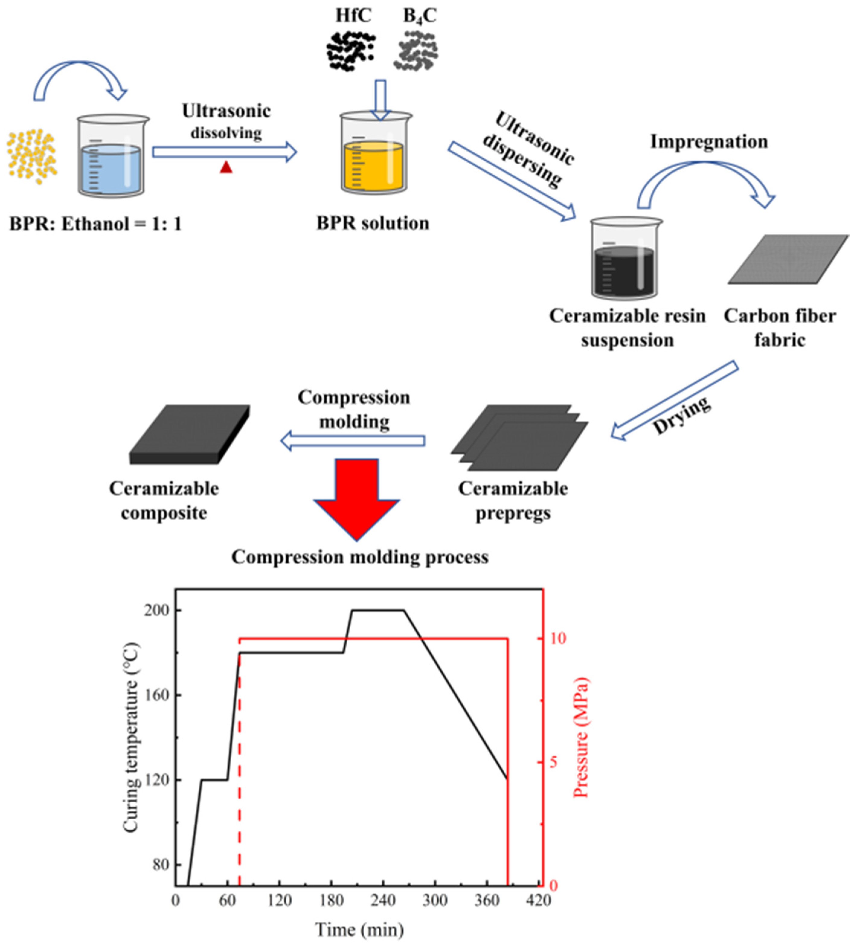
2.2. Fabrication of Ceramizable Composites

The ceramizable composites were fabricated via impregnation and compression molding, as depicted in Figure 1. First, BPR was mixed with anhydrous ethanol in a 1:1 mass ratio under constant magnetic stirring at 600 rpm for 30 min. The yellow BPR solution was obtained by ultrasonicating the mixture at 80 °C for 30 min. Second, the ceramizable filler, as specified in Table 1, was added to the BPR solution and magnetically stirred for 10 min, followed by ultrasonic dispersion for an additional 10 min to achieve a well-dispersed suspension. Third, the carbon fiber scrim fabric was uniformly coated with the ceramizable BPR solution to ensure complete impregnation. The impregnated fabric was air-dried at room temperature to obtain the ceramizable prepreg. The prepregs are then stacked, molded, and cured using a compression process. In this case, 23 layers of prepreg were stacked for samples used for ablative testing and 9 layers of prepreg were stacked for samples used for heat treatment and flexural testing.

2.3. Flexural Test

The flexural strengths of the experimentally prepared composites before and after heat treatment were measured using a universal mechanical testing machine (RGM-4100, Ruge Instrument Co., Ltd., Shenzhen, China). The heat treatment procedure was as follows: Samples were placed in a high-temperature chamber furnace (KSL-1700, Kejing Co., Shenzhen, China) for 20 min at temperatures of 600 °C, 800 °C, 1000 °C, 1200 °C, 1400 °C, and 1600 °C, respectively. After heat treatments, the samples were removed and their flexural strengths were assessed using the three-point flexural method, following the guidelines of the Chinese standard GB/T 1449-2005 [24]. The test parameters included a span of 16d and a crosshead speed of 2 mm/min.
σ = 3 F l / ( 2 b d 2 )
where σ is the flexural strength of the sample, F is the maximum load that the sample is subjected to, b is the width of the sample, and d is the thickness of the sample. The final results were taken as the arithmetic mean of four parallel tests.

2.4. Oxy-Acetylene Ablation Test

The test was conducted according to the oxy-acetylene flame test method stipulated in the national military standard GJB 323A-1996 [25]. Among standard, the gas flow rate of oxygen was 1512 L/h, the gas pressure was 0.4 MPa, the gas flow rate of acetylene was 1116 L/h, the gas pressure was 0.095 MPa, the mixing ratio of oxygen and acetylene was 1.35, the heat flow density of the flame was 4.2 ± 0.2 MW/m2, the flame temperature reached as high as 3000 °C [26,27], the nozzle diameter was 2 mm, the vertical distance between the muzzle and the surface of the composite material was 10 mm, and the ablation time Δt = 20s. The line ablation rate and mass ablation rate were calculated based on the depth change and mass change.
L A R = ( d 1 d 2 ) / t
M A R = ( m 1 m 2 ) / t
where d1 and d2 are the initial thickness of the sample and the thickness after the ablation test, respectively, and m1 and m2 are the initial mass of the sample and the mass after the ablation test. The final results were taken as the arithmetic mean of five parallel tests.

2.5. Characterizations

The microstructure of the ceramizable composites was observed by using a ZEISS SIGMA 300 (Carl Zeiss AG., Jena, Germany) scanning electron microscope (SEM) with an accelerating voltage of 15 keV. Additionally, the elemental distribution was analyzed using an Oxford energy-dispersive X-ray (EDS) spectrometer (Carl Zeiss AG., Jena, Germany). Thermal stability and oxidative corrosion resistance were assessed by using a NETZSCH STA 449 F3 Jupiter simultaneous thermal analyzer (Naichi Scientific Instrument Trading Co., Ltd., Selb, Germany) in the air at a heating rate of 10 °C/min over a temperature range of 0–1400 °C. Residual yield was calculated from Equation (4).
R = m 4 / m 3
where R is the residual yield, and m3 and m4 are the mass of the sample before and after the thermogravimetric tests, respectively.
The Gibbs free energy change was calculated from Equation (5).
G = H T S
where ΔG is the Gibbs free energy change, ΔH is the enthalpy change in the chemical reaction, ΔS is the entropy change, and T is the temperature. ΔG was estimated and provided by the HSC Chemistry 6.0 software package.
The crystal phases were characterized by using X-ray diffraction (XRD) with a D8 Advance model (Bruker Co., Berlin, Germany). Testing parameters were in the range of 5–80°, a scanning rate of 4°/min, a test voltage of 40 kV, and a test current of 400 mA. The crystallinity of the samples was calculated using the split peak fitting method. The lattice constants of the crystals and the mass shares of the components were estimated by MDI Jade 6.5. Elemental compositions were determined using a Thermo Scientific ESCALAB 250Xi X-ray photoelectron spectrometer (XPS) (Thermo Fisher Scientific Co., Waltham, MA, USA). The pass energy and step size for the survey scan were set at 100 eV and 1.0 eV, respectively, while for high-resolution scans were 30 eV and 0.1 eV, respectively.

3. Results and Discussion

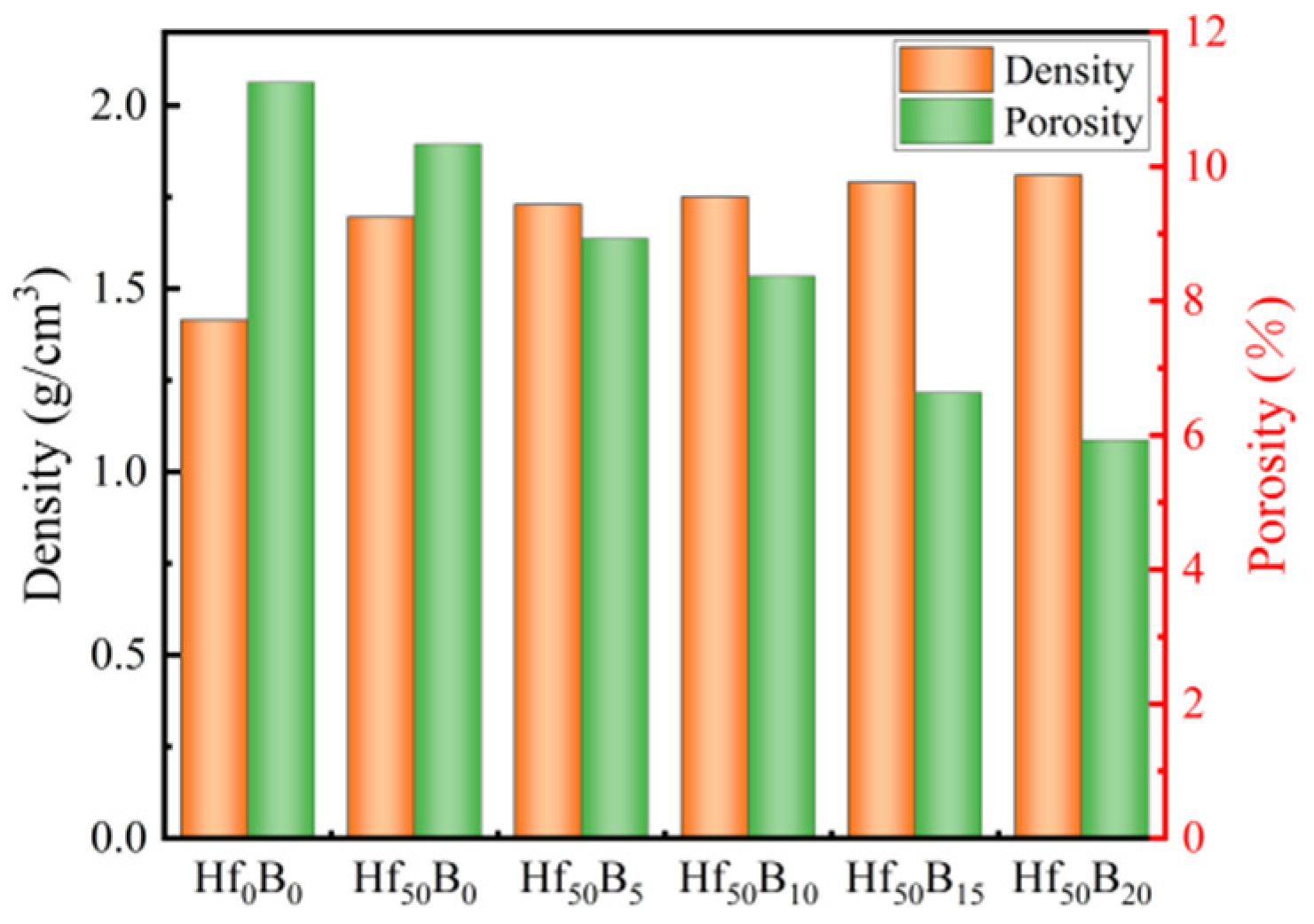
3.1. Density and Porosity of the Ceramizable Composites

During the heating phase of sample preparation, low-boiling-point substances such as formaldehyde and phenol dissolved in the resin will vaporize, and if they are not discharged promptly, the flowing resin will be extruded during the pressurization phase, resulting in a decrease in the density of the sample. In addition, small molecule gases are released during the curing and cross-linking stages to form pores within the material, affecting the denseness of the material. Figure 2 illustrates the density and porosity of the different formulations of the ceramizable composites. The results showed that the addition of both HfC and B4C decreased the porosity of the material. This is due to the fact that during the curing cross-linking stage, HfC and B4C occupied the position of pores and improves the densification of the composites. In addition, the viscosity of the resin fluid increased and less mass was extruded during pressurization. As a result, the density of the ceramizable composites increased from 1.414 g/cm3 for Hf0B0 to 1.695 g/cm3 for Hf50B0 and then gradually increased to 1.810 g/cm3 for Hf50B20. It is noteworthy that the density of the ceramizable composites was less compared to that of the C/C and ceramic-based composites of similar systems whose densities have been reported [28,29]. This indicates that the ceramizable composites have the advantage of being lightweight.

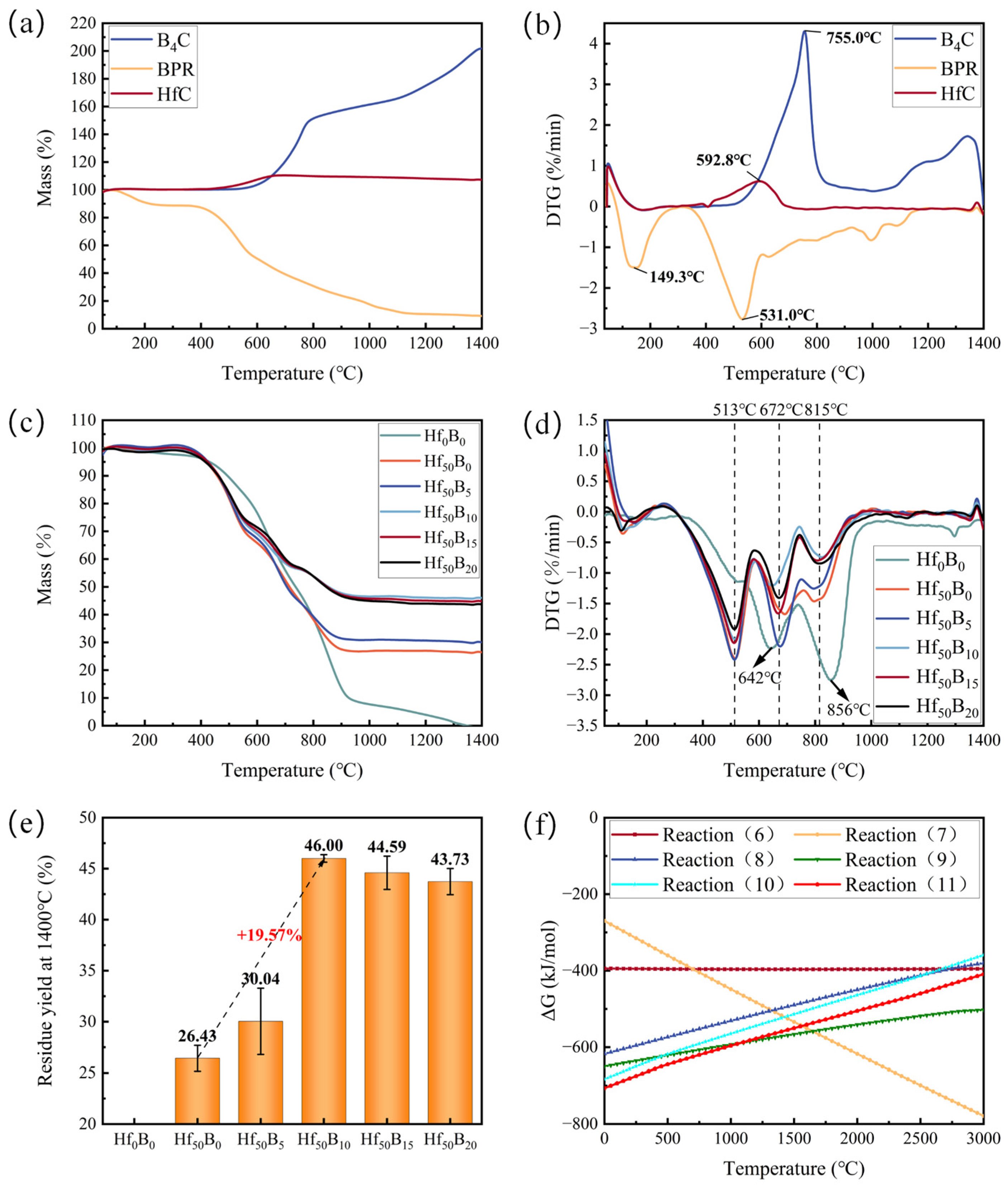
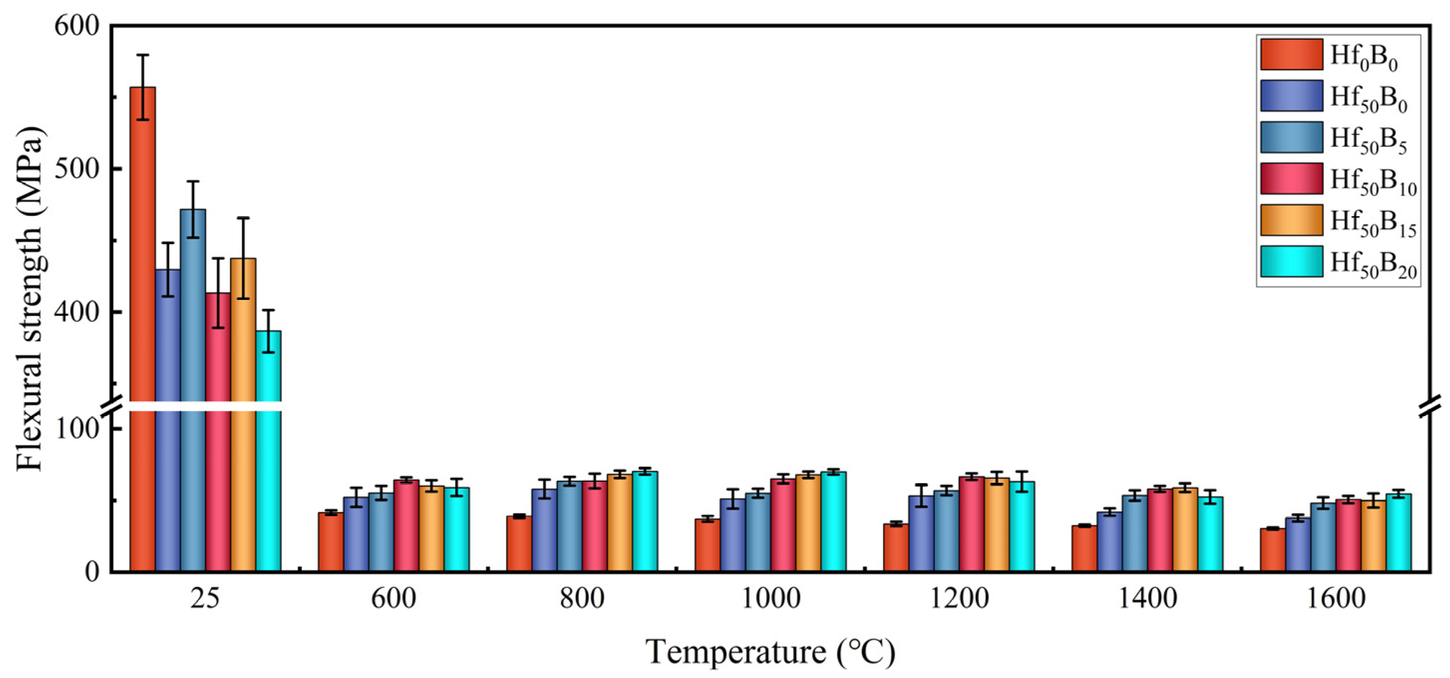
3.2. Thermal Stability, Oxidation Resistance, and Flexural Strength of Ceramizable Composites

Figure 3 illustrates the thermal stability of the materials in air. Figure 3a,b show the thermogravimetric analysis (TGA) as well as the derivative thermogravimetry (DTG) curves of each single component material in air. It can be seen that the mass of BPR was in a decreasing trend, in which the peak decomposition rate temperature of small molecule gasification was 149.3 °C. The peak decomposition rate temperature for the violent cracking reaction was 531.0 °C. The pyrolysis process of BPR has been previously reported. The primary pyrolysis products between 350 °C and 850 °C include phenols, toluene, styrene, aldehydes, carboxylic acids, CO, CO2, H2O, and long-chain olefins such as squalene [23]. Additionally, the main chain of BPR undergoes scission, forming polycyclic aromatic hydrocarbon structures. These structures will subsequently undergo further carbonization to form pyrolytic carbon (PyC). HfC and B4C were involved in the reactions (8)–(11) to increase the residuals through the fixation of oxygen. HfC began to be oxidized at about 400 °C with a maximum reaction rate temperature of 592.8 °C. B4C began to be oxidized at about 500 °C with a maximum reaction rate temperature of 755.0 °C.
C + O 2 ( g ) = C O 2 ( g )
2 C + O 2 ( g ) = 2 C O ( g )
1 / 2 H f C + O 2 ( g ) = 1 / 2 H f O 2 + 1 / 2 C O 2 ( g )
2 / 3 H f C + O 2 ( g ) = 2 / 3 H f O 2 + 2 / 3 C O ( g )
1 / 4 B 4 C + O 2 ( g ) = 1 / 2 B 2 O 3 + 1 / 4 C O 2 ( g )
2 / 7 B 4 C + O 2 ( g ) = 4 / 7 B 2 O 3 + 2 / 7 C O ( g )
Figure 3c shows the TGA curves of the ceramizable composites in the air. The results showed that the temperature for 0% residual yield of Hf0B0 was 1347 °C. The addition of HfC resulted in a 26.43% residual yield of Hf50B0. The addition of B4C significantly increased the mass retention rate at high temperatures, with Hf50B10 having the highest residual yield of 46.00%, which increased by 19.57% compared with that of Hf50B0 (Figure 3e). When the content of B4C exceeded 10 phr, the residual yield of the composites began to decrease. This is attributed to the relatively high saturated vapor pressure of B2O3 at elevated temperatures, which facilitates its volatilization [19].
Figure 3d shows the DTG curves of the composites. The results showed that the peak decomposition temperatures of Hf0B0 were 642 °C and 856 °C. After the addition of HfC, the peak decomposition temperatures of Hf50B0 increased to three. Among them, the first peak decomposition temperature was advanced to 513 °C and the second peak temperature was advanced to 672 °C. The possible reason for the leftward shift in the peak decomposition temperature is that the addition of HfC increased the thermal conductivity of the composite, and heat was thus conducted faster, leading to the earlier cracking of the BPR. With the continued addition of B4C, the thermal conductivity of the composite did not increase significantly, so the peak decomposition temperature remained essentially unchanged. The thermal conductivity of the composites is shown in Table S1. Between 513 °C and 672 °C, the oxidation processes of HfC and B4C offset the mass loss from resin cracking and carbon oxidation, while B4C continued to participate in the oxidation reaction between 672 °C and 815 °C. The generated B2O3, with a low melting point (~450 °C), melts and flows at high temperatures and fills defects such as pores generated by the pyrolysis process, reducing the O2 entry into the interior of the material to contact and react with the carbon fiber pathway [5,14]. As a result, the decomposition degree of the material gradually decreases above 815 °C.
Figure 3f illustrates the Gibbs free energy change curves of carbon fiber, HfC, and B4C involved in the oxidation reaction. The results show that at temperatures less than 1300 °C, HfC and B4C ceramics have lower ΔG values for the oxidation reaction and therefore react more easily with O2. During the pyrolysis process, HfC and B4C participated in oxidation reactions, consuming oxygen and simultaneously generating a substantial amount of CO and CO2 gases. These gases reduced the oxygen concentration at the material surface, thereby mitigating the pyrolysis of the resin and the oxidative corrosion of the carbon fibers.
Figure 4 shows the flexural strength of the ceramizable composites before and after heat treatment at various temperatures. It can be seen that before heat treatment, the addition of ceramics gave an overall decreasing trend in the flexural strength of the composites. This is because the increase in content of ceramizable filler hindered the bonding of the resin with the carbon fibers, and the interfacial bonding force was subsequently reduced. Microcracks were more likely to occur within the composite material during the flexural test, which was macroscopically reflected in the reduction in the flexural strength. As a result of heat treatment, the flexural strength of the material decreased in a cliff-like manner. This was due to the weakening of the interlayer bonding during high-temperature oxidative corrosion and the generation of pores and microcracks within the composite. When bearing loads, the pores and microcracks were more likely to expand until the material broke.
Comparing the flexural strengths of Hf0B0 and Hf50B0, it can be seen that the addition of HfC significantly improved the flexural strength of the composites after heat treatment. Firstly, HfC was easier to oxidize and produced CO2 gas, which created an oxygen-deficient atmosphere local. Secondly, after heat treatment, the dispersed HfC and HfO2 particles produced a “pinning effect”, preventing cracks from spreading, and thus the flexural strength was significantly improved.
The addition of B4C could help to fill and heal the generated pores and cracks during the resin pyrolysis through the flow of molten B2O3 at high temperatures. With the increasing content of B4C, more pores and cracks would be healed. As a result, the flexural strength of the heat-treated composites rose overall with increasing B4C content. Between 800 °C and 1200 °C, the flexural strength of Hf50B10, Hf50B15, and Hf50B20 did not change much. This is because in this temperature interval, B4C, with the highest oxidation rate, preferentially participated in the oxidation process. When the heat treatment temperature reached 1400 °C, most B2O3 was vaporized, the filled pores and cracks were re-exposed, and the surface and interior of the material were subjected to more severe high-temperature oxidative corrosion, and the flexural strength showed a significant decrease. After the temperature reached 1600 °C, the change in flexural strength was not as large as that at 1400 °C, which was attributed to the decrease in the cross-sectional area of the strip samples after heat treatment at 1600 °C. As a result, the synergistic effect of HfC and B4C resulted in the flexural strength of Hf50B20 of 54.65 MPa after heat treatment at 1600 °C, which increased by 79.59% and 44.84% by comparing with that of Hf0B0 and Hf50B0, respectively. Compared with the flexural strength results of similar systems, the advantages of the HfC-B4C system are evident (Figure S1 and Table S2).

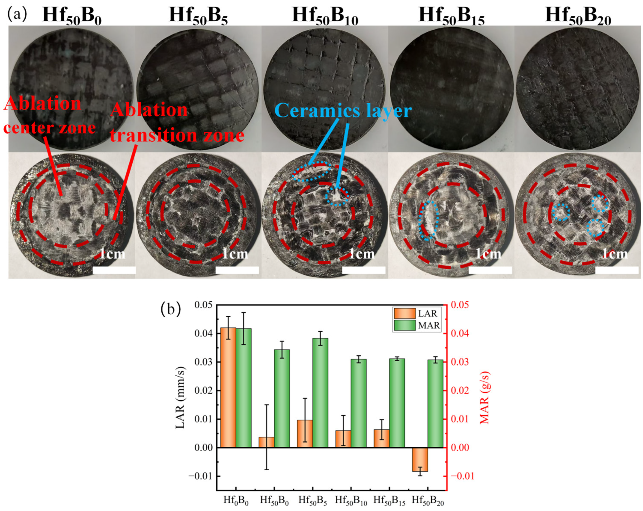
3.3. Ablation Resistance of Ceramizable Composites

In the oxy-acetylene ablation test, samples were exposed to an oxy-acetylene flame with a heat flux density of 4.2 MW/m2 for 20 s. The enhancements of ablation resistance by HfC and B4C were investigated. Figure 5a illustrates the surface images of the samples before and after ablation, where the surface of the samples is divided into three areas by dashed lines: the ablation center zone, the ablation transition zone, and the edge zone. The image shows that the ablation area in the center decreases with the increase in the B4C content. Between the intervals of the areas of Hf50B10, Hf50B15, and Hf50B20, there are white ceramic layers, which are the result of the combination of high-speed airflow scouring and B2O3 glass phase adhesion.
Figure 5b depicts the linear and mass ablation rates of the ceramizable composites. The LAR and MAR of Hf0B0 were 4.20 × 10⁻² mm/s and 4.17 × 10⁻² g/s, respectively. The LAR and MAR of Hf50B0 with the addition of HfC were 3.67 × 10⁻³ mm/s and 3.43 × 10⁻² g/s, respectively. The results showed that the LAR was reduced by an order of magnitude, and that the incorporation of HfC enhanced the material resistance to ablation by an extremely high degree. Under the flame of oxy-acetylene at 3000 °C, B2O3 evaporates or sublimates rapidly, and part of the HfO2 (melting point 2758 °C) also melts and sticks to the carbon fiber. HfC (melting point 3958 °C), which has a very high melting point, is resistant to high-temperature ablation. The increased mass ablation rate for Hf50B5 compared to Hf50B0 is due to the volatilization of B2O3, whereas the reduced mass ablation rates for Hf50B10, Hf50B15, and Hf50B20 were due to the fact that the ceramic particles and cracked carbon were adhered by the B2O3 glassy phase, which reduces the amount of mass that could be stripped off by the high-velocity gas stream. Notably, the LAR and MAR of Hf50B20 were −8.33 × 10⁻³ mm/s and 3.08 × 10⁻² g/s, respectively, with a 9.9% decrease in MAR compared to Hf50B0. The transition of the LAR from positive to negative indicates that the volume of the composite expanded during the ablation process, and the increase in thickness prolonged the ablation resistance time. It was expected that the composites would have a longer operational time in harsh aerodynamic environments. The HfC–B4C system has a significant advantage in terms of ablation performance when compared to ablation test results from various systems with consistent ablation conditions (Figure S2 and Table S3).

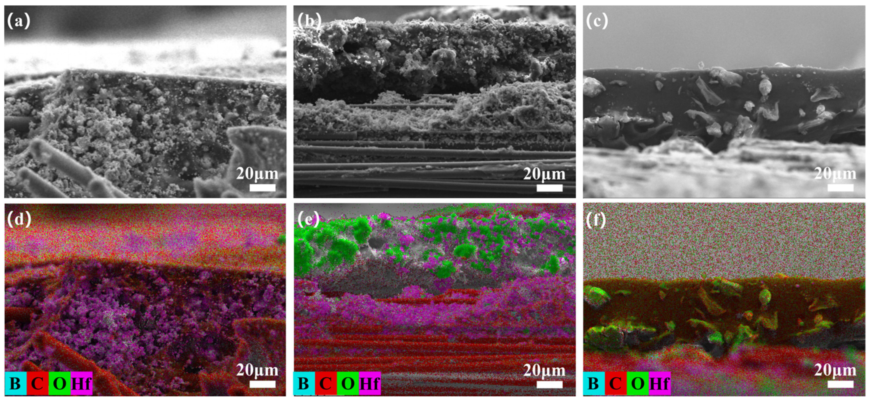
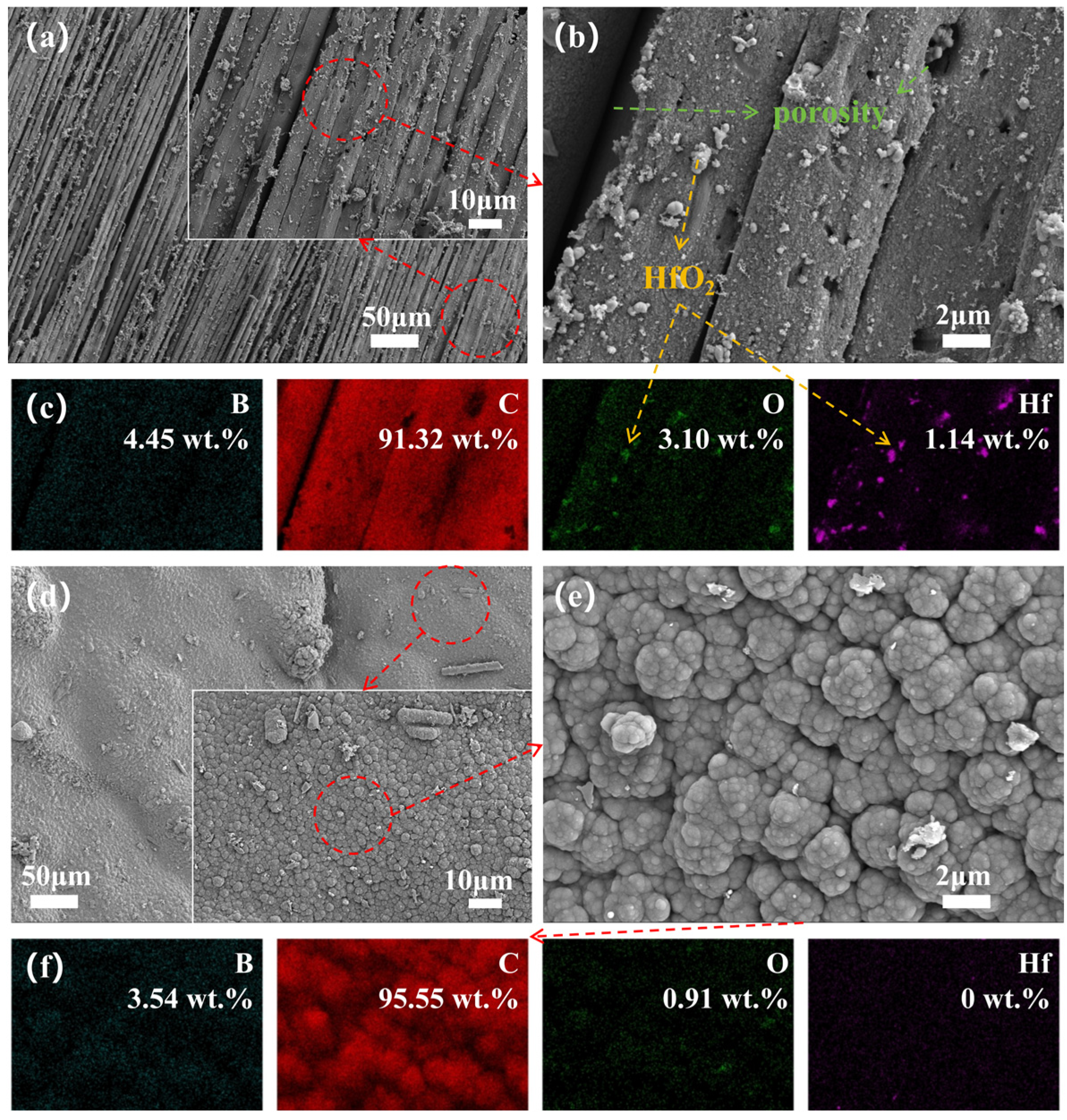
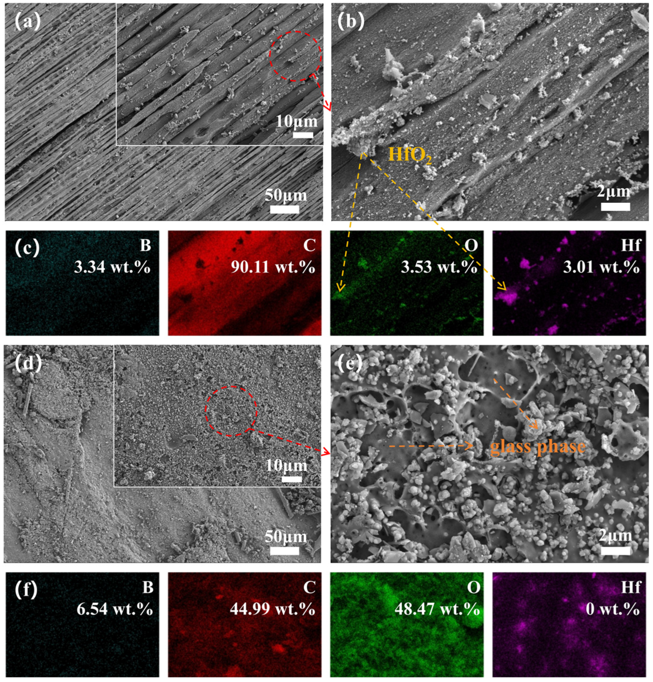
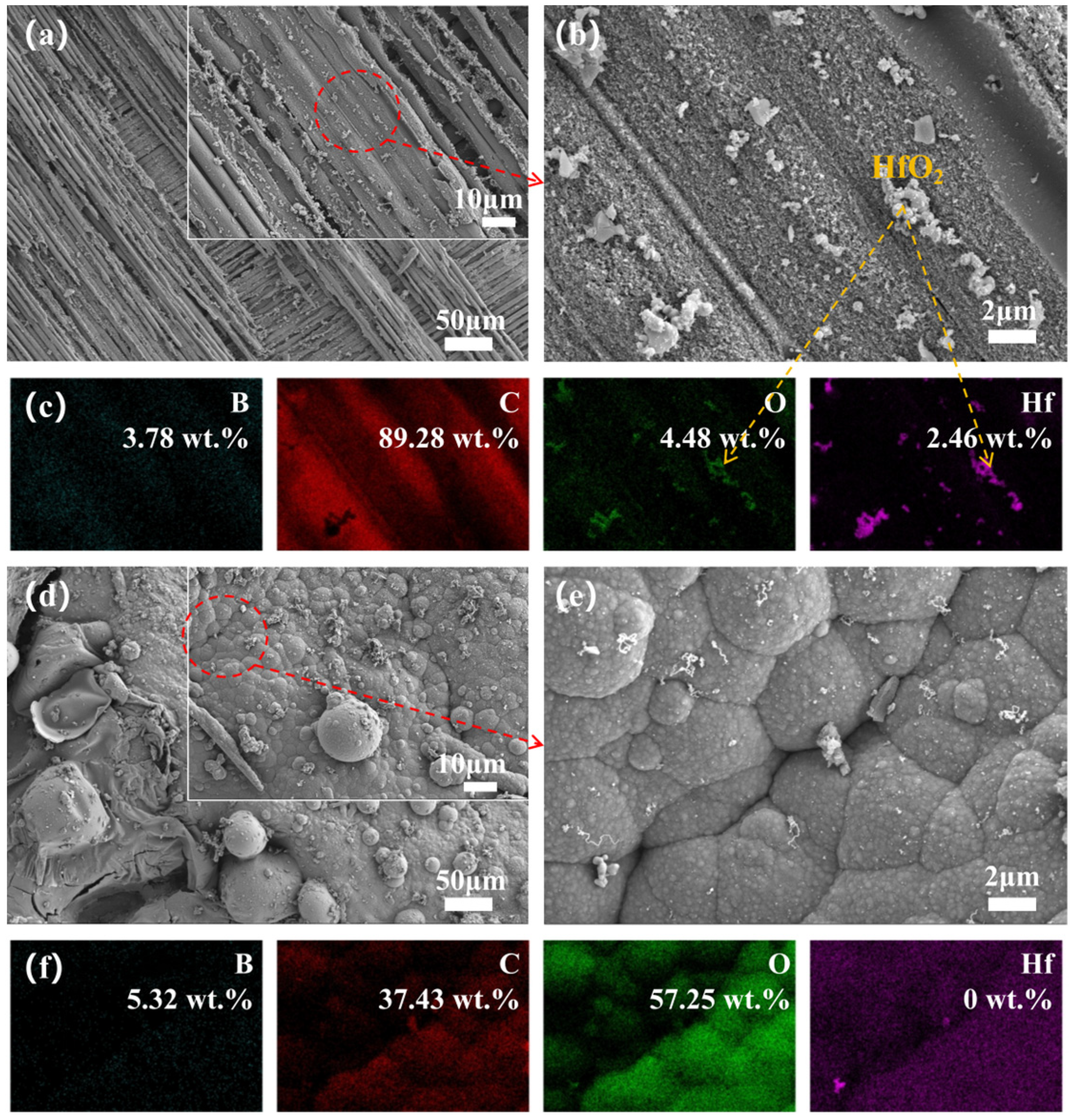
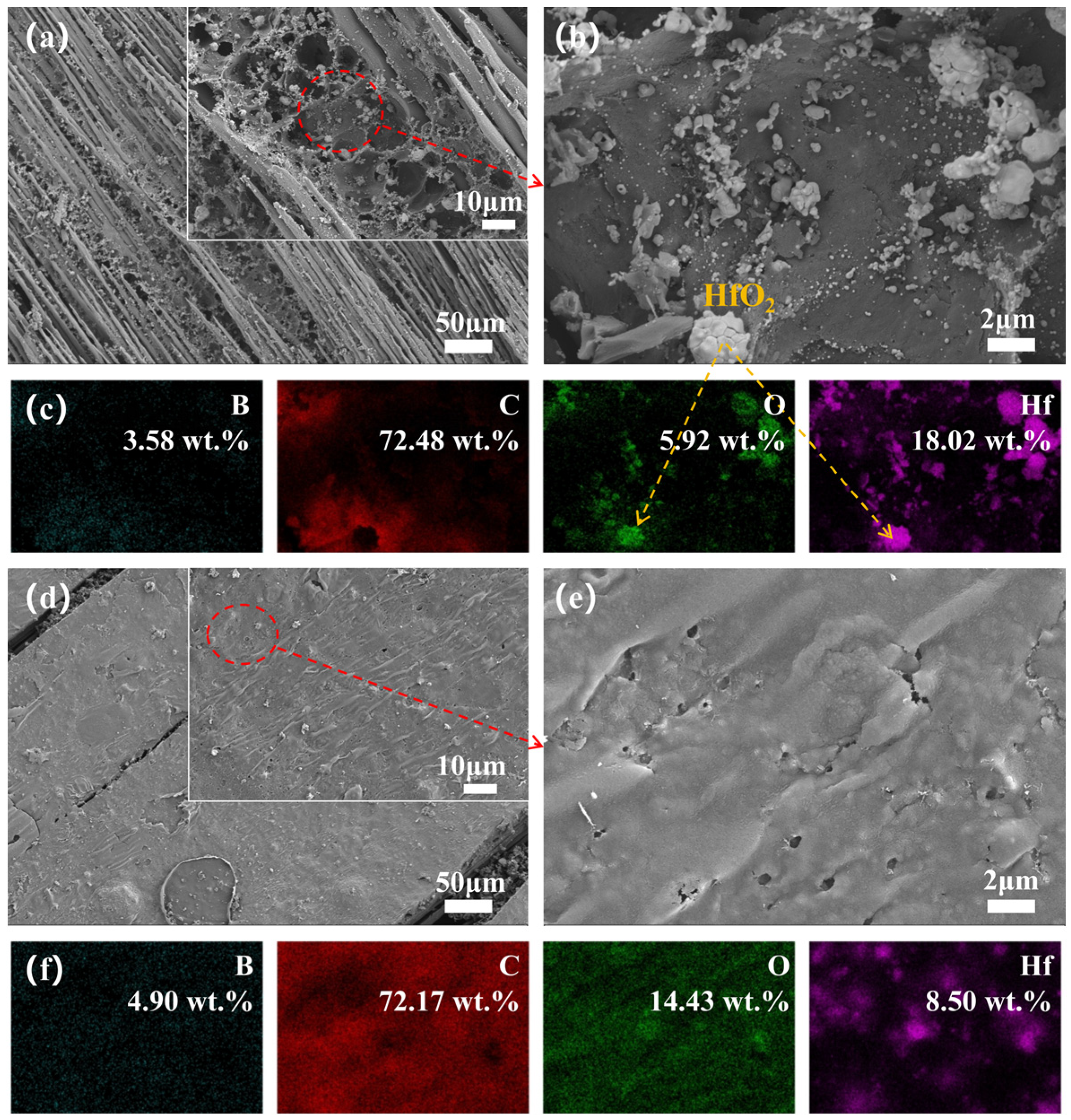
3.4. Microstructure Evolution

To deeply investigate the effect of ceramizable fillers on the oxidation resistance of the composites, we observed the cross-sectional microstructure of the oxide layer on the surface of the flexural samples and recorded elemental mappings to better analyze the elemental distribution. During heat treatment, the resin cracked to produce gases, leading to a decrease in interfacial strength. Concurrently, the escape of these gases increased interlayer stresses, which disrupted the structure of the material and created numerous pores, leading to delamination and peeling-off under severe conditions. Figure 6a shows a cross-sectional micrograph of Hf50B0 after heat treatment at 1600 °C for 20 min. An important consequence of the oxidation of HfC was the formation of a fluffy, porous, coral-like HfO2 structure (Figure 6d), where stresses generated by volumetric expansion during the crystallization process led to more pores, acting as conduits for the continuous inward erosion of O2 and heat flow. After adding 10 phr of B4C, the oxide layer on the surface of the composite material melted and flowed to form a ceramic layer (Figure 6b,e), which exhibited a repairing effect on some of the pores. However, the melt was not enough, and the ceramic layer on the surface was loose and not able to tightly bond with the interior, with cracks still present. When the B4C content was increased to 20 phr, a ceramic layer with uniform thickness and close bonding between the inside and outside was formed on the surface of the composite material (Figure 6c,f), and the pores were filled by B2O3 melt. This not only reduced the pathways for oxidation and heat flow corrosion but also bonded the HfO2 particles and PyC together, resulting in a denser structure.
To elucidate the significant differences in ablation behavior, we observed the surface micro-morphology of the central region and transition zone of the ablated surface and recorded elemental mappings for a detailed analysis of elemental distribution. The microscopic images and elemental distribution of the ablated surface for Hf50B0 are depicted in Figure 7. The ablation center exhibits a multitude of exposed carbon fibers along with minor PyC and ceramic particles, suggesting severe ablation damage to Hf50B0. The bonding of HfC, HfO2, and PyC with the resin and carbon fibers was very fragile and easily detached under the washing effect of the high-speed heat flow. Conversely, in the ablation transition zone, extensive PyC formation occurred without exposed carbon fibers, attributed to the diminished temperature and scouring effects at the flame’s periphery.
The morphology of the ablation centers in Hf50B5 (Figure 8a) appears to be no better than that in Hf50B0. Surrounding the Hf element, an oxide distinct from HfO2 (Figure 8b,c) was observed, identified as B2O3, suggesting that only a small amount of molten B2O3 acted as an adhesive in the high-temperature environment. This is partly due to the low content of B4C and, on the other hand, the high-temperature volatilization and the scouring of the high-speed heat flow reduced the content of B2O3 on the surface of the material. In contrast to Hf50B0, the ablation transition zone of Hf50B5 is a scene of oxides mixed with PyC, and most of these oxides are B2O3 glass phase.
Hf50B10 exhibits continuous carbon layers at the center of the ablated surface (Figure 9b), originating from boron phenolic resin. The area of exposed carbon fibers was reduced, but relative to the presence of multiple broken carbon fibers still can be seen, indicating that the oxidative corrosion of the carbon fibers and PyC was still severe. In the ablation transition zone, the mass percentage of Hf was 0 wt.%. There are two possible reasons. One is that the oxides and PyC generated on the surface covered the Hf-based material. The other is that the Hf material was washed away from the surface by the high-speed heat flow. The high-temperature environment in the ablation transition zone resembles static calcination, and considering the morphology of the static calcination cross-section (Figure 6b), the first scenario appears more plausible.
The ablation centers of Hf50B15 (Figure 10a) and Hf50B20 (Figure 11a) were similar to those of Hf50B10, but the surfaces were covered with more PyC, which suggests that oxidative corrosion was further reduced. In the ablation transition zone, both Hf50B15 (Figure 10e) and Hf50B20 (Figure 11e) formed a ceramic layer with a flat surface. Among them, Hf50B20 had fewer holes on the surface and the ceramic layer was denser.

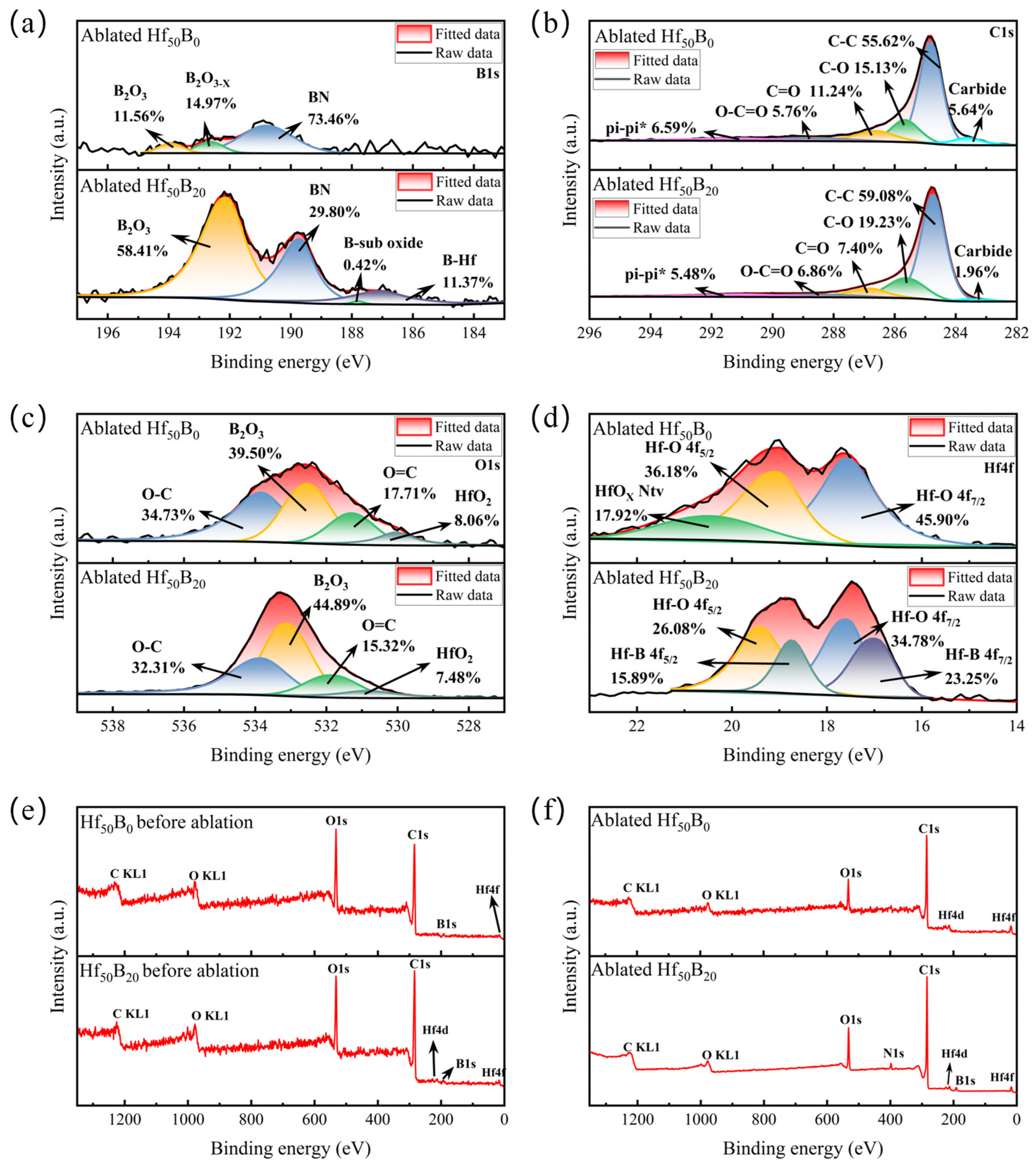
3.5. Phase Evolution

The phases of the composites were characterized and analyzed using XRD and XPS techniques. An observation of the XRD image of Hf50B0 (Figure 12a) reveals that the ablated sample contains HfC (PDF#39-1491), m-HfO2 (PDF#34-0104), and trace amounts of c-HfO2 (PDF#53-0560). In addition, there was a broad peak between 20° and 30°, which is characteristic of amorphous diffraction. After fitting, the crystallinity of Hf50B0 was calculated to be 69.00%. The mass ratio of HfC, m-HfO2, and c-HfO2 was 53.34: 45.92: 0.74.
2 B 2 O 3 + 7 C = B 4 C + 6 C O ( g )
H f O 2 + 5 C + B 2 O 3 = H f B 2 + 5 C O ( g )
B 2 O 3 + 3 C + N 2 ( g ) = 2 B N + 3 C O ( g )
In the XRD spectrum of Hf50B20 (Figure 12b), the characteristic sharp peaks at 2θ = 25.6°, 32.8°, and 42.1° demonstrate the presence of HfB2 (PDF#38-1398) in the composite material, which has excellent ablation and oxidation resistance as a kind of ultra-high-temperature ceramic [30,31,32]. The crystallinity of Hf50B20 was 62.25%, and the mass ratio of HfC, m-HfO2, c-HfO2, and HfB2 was 29.04:62.75:1.07:7.14. More HfO2 adhered to the ablation surface. The area of the broad peak in Hf50B20 is much larger, indicating that more amorphous phase material was generated on the ablation surface. In the present system, the amorphous phase substances may include but are not limited to B2O3 and PyC [33,34,35]. Cell pictures and lattice parameters of all crystals were organized in Figure S3 and Table S4.
Figure 12c,d demonstrate the Gibbs free energy change curves and enthalpy change curves for reactions (12)–(14). During the ablation process, these reactions have ΔG < 0, all of which tend to react spontaneously. Moreover, these reactions have ΔH > 0, which could absorb heat during the reaction and slow down the rate of temperature rise on the material surface. The gases such as CO generated by the reactions could form a gas film as well as dilute the oxygen concentration on the surface of the material, thus reducing the oxidative corrosion of the material and the mechanical stripping caused by the high-speed airflow.
Figure 13a,b show the XPS narrow-spectrum images of B1s and C1s of the ablated phases of Hf50B0 and Hf50B20. The B elements in Hf50B0 are derived from BPR. The results showed that most of the B elements in Hf50B0 were involved in the reaction (14) to produce BN. The presence of BN enhances the interface bonding, leading to a more dense surface structure and improved ablation resistance [36,37,38]. However, the thermal conductivity of the material is also increased [39]. The remaining fraction forms complete B2O3 and the other fraction forms less oxygenated B2O3−X. In Hf50B20, there is also a fraction of elemental B that reacts with HfO2 to form HfB2 (reaction (13)). The binding energies of both BN and B2O3 were reduced by adding 20 phr of B4C. It indicates that the excessive B content leads to the increase in disorder inside the glassy phases of BN and B2O3. HfB2 was not detected in Hf50B0, the probable reason for this is that the formed ceramic particles are stripped by the high velocity gas flow, and thus are not able to be retained on the ablative surface. The absence of relevant characteristic peaks in XRD indicates that the BN was amorphous α-BN. No B4C was detected, indicating that all of the B4C on the surface was involved in the reaction, and also indicating that the amount of B4C produced by the reaction (12) was too low. XPS narrow spectra of C1s showed that the cleavage behavior of BPR did not change with the addition of B4C, and the cleavage products contained phenols, aldehydes, ethers, carboxylic acids, and graphite. The extent of graphitization of cracked carbon increased with an increasing B4C content (Figure S4). The carbide was unreacted HfC. The narrow spectrum of O1s further confirmed the cleavage behavior of BPR (Figure 13c).
Figure 13d shows the XPS narrow spectrum of Hf4f after ablation of Hf50B0 and Hf50B20. The results show that in Hf50B0, the Hf element exposed on the surface continues to react to form the natural oxide HfOX, while the surface of Hf50B20 has a glassy phase that helps to insulate the oxygen, so it is difficult to form the natural oxide. Based on XPS spectroscopy, the ratio of HfO2 to HfB2 in Hf50B20 is about 3:2, indicating that HfB2 was mainly generated on the surface of ceramic particles.
Figure 13e,f show the full XPS spectra of Hf50B0 and Hf50B20 before and after ablation. The results surface that the elemental changes before and after ablation of Hf50B0 are not obvious. The intensity of the binding energy peaks associated with the N element in the XPS full spectrum was too low. This also indicates that there was little BN content in Hf50B0. However, the binding energy peaks associated with elemental N can be clearly observed in the XPS image of Hf50B20 after ablation, further confirming that BN is the main ablation product of Hf50B20.

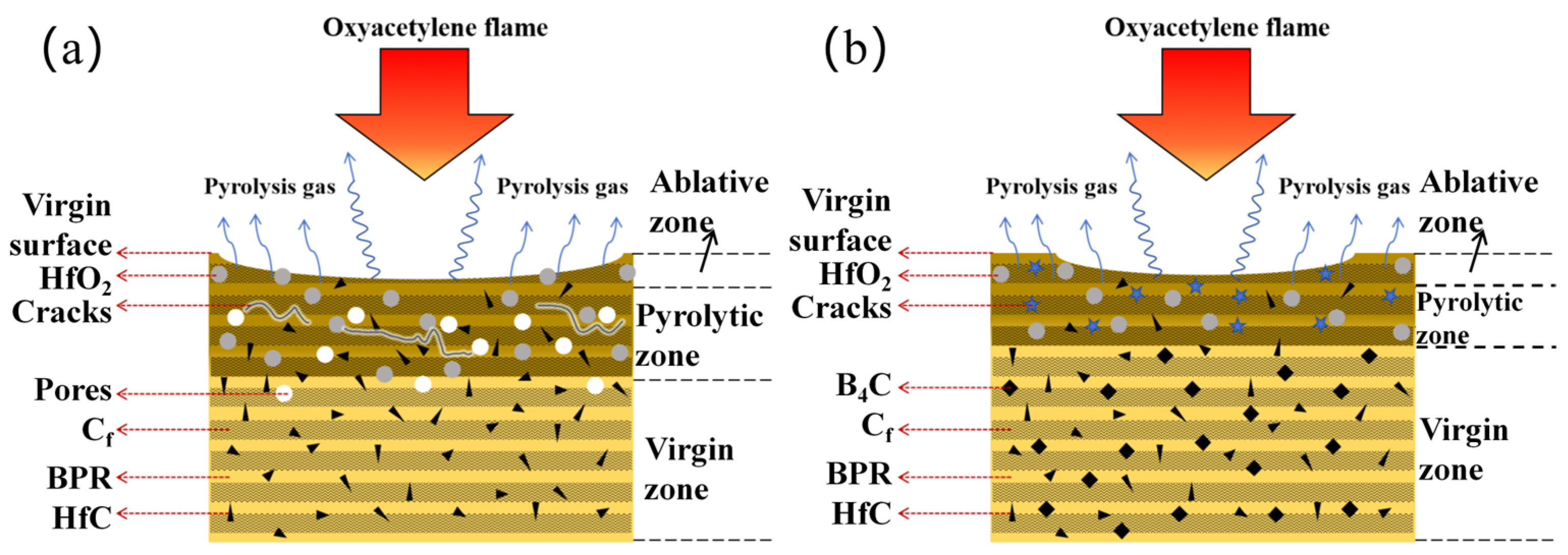
3.6. Ablation Mechanisms

Based on the studies of the ablation behavior, microstructural evolution, and phase evolution, the possible ablation mechanisms were as follows:
For the Hf50B0 composite (Figure 14a), the pyrolysis of the BPR results in the detachment of discrete HfC and HfO2 particles, which were subsequently removed by high-speed airflow. This led to the exposure of a large number of carbon fibers on the ablation surface, along with an enlarged central ablation area.
After adding B4C, the ablation resistance of the composite material was improved. Taking Hf50B20 as an example (Figure 14b), the ablation surface was covered with a ceramic layer, so the area of carbon fibers exposed was reduced. The ceramic layer mainly consisted of ablation-resistant ceramics (HfC, HfO2, and HfB2 particles) as well as a continuous glass phase. The glassy phase composed mainly of B2O3 and BN exhibits fluidity, allowing it to fill and repair cracks and pores generated by the pyrolysis of the substrate. The ablation-resistant ceramics were adhered to or embedded in the glass phase.
In summary, a B–C–N–O–Hf multicomponent dense ceramic layer was constructed on the ablation surface of Hf50B20, forming an effective ablation-resistant barrier. The layer significantly impeded thermochemical erosion of the carbon fibers and PyC, while preventing thermomechanical stripping. Additionally, the strong heat absorption of HfO2, B2O3, and PyC during carbothermal reactions further enhanced the thermal protection performance of the material.

4. Conclusions

This report presents our study of the development and characterization of HfC–B4C-modified Cf/BPR ceramizable composites, demonstrating their superior oxidative corrosion and ablation resistance. As the B4C content increased, the density of the composites increased, while the porosity decreased. The residual yield at 1400 °C first increased and then decreased. The highest residual yield of 46.0% was found for Hf50B10. There was no obvious pattern in the bending strength, but the bending strength of the samples with added B4C was significantly higher than that of the unadded ones. The flexural strength of Hf50B20 was as high as 54.65 MPa after heat treatment at 1600 °C for 20 min. A dense multicomponent ceramic layer was formed on the surface of the material after heat treatment. In the ablation test, both LAR and MAR first increased and then decreased with the increase in the B4C content. At a heat flux density of 4.2 MW/m2 for 20 s, the LAR of Hf50B20 was as low as −8.33 × 10⁻³ mm/s, and the MAR was 3.08 × 10⁻² g/s. In summary, Hf50B20 has the best overall thermal protection performance.
The ablation mechanism was further revealed. Due to the synergistic effect of HfC and B4C, a dense B–C–N–O–Hf ceramic layer was formed in situ on the ablated surface. As an effective thermal protection barrier, this ceramic layer significantly prevents the thermochemical erosion of carbon fibers and PyC and prevents stripping by high-speed airflow. The carbothermal reaction between HfO2, B2O3, and PyC contributes to the thermal insulation capability of the composite due to its strong heat-absorption effect. These findings confirm the potential of HfC–B4C-modified Cf/BPR ceramizable composites for applications in thermal protection systems.

Supplementary Materials

The following supporting information can be downloaded at: https://www.mdpi.com/article/10.3390/polym17101412/s1. Figure S1: The flexural strength for similar studies in the literature; Figure S2: The ablation rates for similar studies in the literature; Figure S3: Cell images of (a) HfC, (b) m-HfO2, (c) c-HfO2 and (d) HfB2; Figure S4: Raman spectra of Hf50BX surface phases after ablation; Table S1: The thermal conductivity and standard deviation of composites; Table S2: The specific values of flexural strength for similar studies in the literature; Table S3: The specific values for ablation rates for similar studies in the literature; Table S4: Cellular parameters of HfC, m-HfO2, c-HfO2 and HfB2.

Author Contributions

Conceptualization, X.Y. and W.H.; Formal analysis, H.W.; Investigation, H.W.; Methodology, H.W., W.Z., and Z.D.; Resources, W.H.; Supervision, W.H.; Writing—original draft, H.W.; Writing—review and editing, X.Y. All authors have read and agreed to the published version of the manuscript.

Funding

This work was supported by the Fundamental Research Funds for Central Universities (WUT:2023III012JL, 2023III004GX and 104972024KFYd0017), Wuhan Key R&D Program (2024010702030141) and Laboratory Self-initiated Research Project of Chaozhou Branch Center of the Guangdong Provincial Laboratory of Chemistry and Fine Chemical Engineering (HJL2023002).

Institutional Review Board Statement

Not applicable.

Data Availability Statement

The original contributions presented in this study are included in the article/Supplementary Material. Further inquiries can be directed to the corresponding authors.

Conflicts of Interest

The authors declare no conflicts of interest.

Abbreviations

The following abbreviations are used in this manuscript:
CfCarbon fiber
PhPhenolic resin
HfCHafnium carbide
B4CBoron carbide
LARLinear ablation rate
MARMass ablation rate
TPSThermal protection system
UHTCsUltra-high-temperature ceramics
BPRBoron phenolic resin
SEMScanning electron microscope
EDSEnergy-dispersive X-ray
XRDX-ray diffraction
XPSX-ray photoelectron spectrometer
TGAThermogravimetric analysis
DTGDerivative thermogravimetry
PyCPyrolytic carbon
ΔGGibbs free energy change
ΔHEnthalpy change

References

  1. Li, W.; Huang, J.; Zhang, Z.; Huang, H.; Liang, J.; Wang, L. Evaluation Method and Key Factor Analysis for Thermal Protection Performance of Multifunctional Integrated Ablative Materials. Polym. Compos. 2020, 41, 5043–5058. [Google Scholar] [CrossRef]
  2. Wu, D.; Lin, L.; Ren, H. Thermal/Vibration Joint Experimental Investigation on Lightweight Ceramic Insulating Material for Hypersonic Vehicles in Extremely High-Temperature Environment up to 1500 °C. Ceram. Int. 2020, 46, 14439–14447. [Google Scholar] [CrossRef]
  3. Mirzapour, M.A.; Haghighat, H.R.; Eslami, Z. Effect of Zirconia on Ablation Mechanism of Asbestos Fiber/Phenolic Composites in Oxyacetylene Torch Environment. Ceram. Int. 2013, 39, 9263–9272. [Google Scholar] [CrossRef]
  4. Biamino, S.; Antonini, A.; Eisenmenger-Sittner, C.; Fuso, L.; Pavese, M.; Fino, P.; Bauer, E.; Badini, C. Multilayer SiC for Thermal Protection System of Space Vehicles with Decreased Thermal Conductivity through the Thickness. J. Eur. Ceram. Soc. 2010, 30, 1833–1840. [Google Scholar] [CrossRef]
  5. Natali, M.; Kenny, J.M.; Torre, L. Science and Technology of Polymeric Ablative Materials for Thermal Protection Systems and Propulsion Devices: A Review. Prog. Mater. Sci. 2016, 84, 192–275. [Google Scholar] [CrossRef]
  6. Costa E Silva, S.F.; Machado, H.A.; Bittencourt, E. Effect of the Fiber Orientation Relatively to the Plasma Flow Direction in the Ablation Process of a Carbon-Phenolic Composite. J. Aerosp. Technol. Manag. 2015, 7, 43–52. [Google Scholar] [CrossRef]
  7. Pesci, P.G.S.; Araújo Machado, H.; De Paula E Silva, H.; Paterniani Rita, C.C.; Filho, G.P.; Botelho, E.C. Numerical-Experimental Analysis of a Carbon-Phenolic Composite via Plasma Jet Ablation Test. Mater. Res. Express 2018, 5, 065601. [Google Scholar] [CrossRef]
  8. Li, B.; Li, H.; Yao, X.; Zhu, X.; Liu, N. Preparation and Ablation Resistance of ZrC Nanowires-Reinforced CVD-ZrC Coating on Sharp Leading Edge C/C Composites. Appl. Surf. Sci. 2022, 584, 152617. [Google Scholar] [CrossRef]
  9. Liu, H.; Ma, H.; Chang, Y.; Zhou, X. Ablation and Mechanical Properties of ZrC-Reinforced PBI Resin Matrix Composites. Ceram. Int. 2023, 49, 15527–15535. [Google Scholar] [CrossRef]
  10. Ren, J.; Zhang, Y.; Zhang, P.; Li, T.; Li, J.; Yang, Y. Ablation Resistance of HfC Coating Reinforced by HfC Nanowires in Cyclic Ablation Environment. J. Eur. Ceram. Soc. 2017, 37, 2759–2768. [Google Scholar] [CrossRef]
  11. Pan, X.; Niu, Y.; Liu, T.; Zhong, X.; Li, C.; Shi, M.; Zheng, X.; Ding, C. Ablation Behaviors of ZrC-TiC Coatings Prepared by Vacuum Plasma Spray: Above 2000 °C. J. Eur. Ceram. Soc. 2019, 39, 3292–3300. [Google Scholar] [CrossRef]
  12. Shichalin, O.O.; Ivanov, N.P.; Seroshtan, A.I.; Nadaraia, K.V.; Simonenko, T.L.; Gurin, M.S.; Kornakova, Z.E.; Shchitovskaya, E.V.; Barkhudarov, K.V.; Tsygankov, D.K.; et al. Spark Plasma Sintering of Ti2AlC/TiC MAX-Phase Based Composite Ceramic Materials and Study of Their Electrochemical Characteristics. Ceram. Int. 2024, 50, 53120–53128. [Google Scholar] [CrossRef]
  13. Xu, X.; Pan, X.; Niu, Y.; Li, H.; Ni, D.; Huang, S.; Zhong, X.; Zheng, X.; Sun, J. Difference evaluation on ablation behaviors of ZrC-based and ZrB2-based UHTCs coatings. Corros. Sci. 2021, 180, 109181. [Google Scholar] [CrossRef]
  14. Li, H.; Yao, D.; Fu, Q.; Liu, L.; Zhang, Y.; Yao, X.; Wang, Y.; Li, H. Anti-Oxidation and Ablation Properties of Carbon/Carbon Composites Infiltrated by Hafnium Boride. Carbon 2013, 52, 418–426. [Google Scholar] [CrossRef]
  15. Wang, D.; Ding, Z.; Zhang, C.; Zhao, J.; Lei, Y.; Zhang, G.; Zheng, G. Mechanical Properties and Thermal Shock Resistance of TiB2-B4C Composite Ceramic Tool Materials at Microscopic Scale. Int. J. Appl. Ceram. Technol. 2024, 21, 3485–3500. [Google Scholar] [CrossRef]
  16. Liu, H.; Ma, H.; Xu, Y.; Zhou, X. Ablation Properties of SiC-Reinforced PBI Resin Matrix Composites under High-Energy Continuous Laser Ablation. Prog. Org. Coat. 2024, 186, 107964. [Google Scholar] [CrossRef]
  17. Deng, Z.; Yang, X.; Yu, X.; Huang, Z.; Zhu, D.; Shi, M. High Temperature Flexural Strength, Microstructure, Phase Evolution and Anti-Oxidation Mechanism of Al-Coated Carbon Fiber/Boron Phenolic Resin Ceramizable Composite Modified with TiB2 and B4C. Ceram. Int. 2023, 49, 25003–25015. [Google Scholar] [CrossRef]
  18. Zou, Z.; Qin, Y.; Chang, K.; Huang, Z. Thermal Properties and Oxidative Corrosion Behaviour of HfB2-SiB6 Ceramicizable Phenolic Resin Matrix Composites. Corros. Sci. 2023, 221, 111340. [Google Scholar] [CrossRef]
  19. Deng, Z.; Wu, Y.; Shi, M.; Yang, X.; Huang, Z. Ablation Behavior, Microstructure, Phase Evolution and in Situ Ceramization Mechanism of ZrC-LaB6 Modified Carbon Fiber/Phenolic Resin Ceramizable Composite. Polym. Degrad. Stab. 2023, 218, 110584. [Google Scholar] [CrossRef]
  20. Deng, J.; Hu, K.; Lu, B.; Zheng, B.; Fan, S.; Zhang, L.; Cheng, L. Influence of B4C on Oxidation Resistance of PSN/Borosilicate Glass-B4C Field-Based Repair Coating of C/C Aircraft Brake Materials at 700–900 °C. Ceram. Int. 2019, 45, 20860–20872. [Google Scholar] [CrossRef]
  21. Houssain, H.; Islak, S.; Okay, F.; Cabbar, T. Microstructure, Mechanical, and Oxidation Properties of Mo-SiC/B4C Hybrid Composites. Ceram. Int. 2025, 51, 10375–10382. [Google Scholar] [CrossRef]
  22. Guo, Q.; Song, J.; Liu, L.; Zhang, B. Factors Influencing Oxidation Resistance of B4C/C Composites with Self-Healing Properties. Carbon 1998, 36, 1597–1601. [Google Scholar] [CrossRef]
  23. Zhu, D.; Huang, Z.; Shi, M.; Qin, Y.; Zou, Z.; Deng, Z. High Char Yield BPR Modified with ZrSi2 and B4C: Pyrolysis Kinetic Behavior and Structure Evolution. J. Therm. Anal. Calorim. 2023, 148, 789–805. [Google Scholar] [CrossRef]
  24. GB/T 1449-2005; Fibre-Reinforced Plastic Composites-Determination of Flexural Properties. China Building Materials Federation: Beijing, China, 2005.
  25. GJB 323A-1996; Test Methods for Ablation of Ablators. Commission for Science, Technology and Industry for National Defense: Beijing, China, 1996.
  26. Weng, Y.; Yang, X.; Chen, F.; Zhang, X.; Shi, A.; Yan, J.; Huang, Q. Effect of CVI SiC Content on Ablation and Mechanism of C/C-SiC-ZrC-Cu Composites. Ceram. Int. 2022, 48, 7937–7950. [Google Scholar] [CrossRef]
  27. Niu, Z.; Xin, Y.; Wang, L.; Shen, S.; Ma, X.; Chen, B.; Wang, C.; Chen, F.; Zhang, C.; Hou, X. Two Birds with One Stone: Construction of Bifunctional-POSS Hybridized Boron-Silicon Ceramicized Phenolic Composites and Its Ablation Behavior. J. Mater. Sci. Technol. 2023, 141, 199–208. [Google Scholar] [CrossRef]
  28. Zhang, J.; Xin, Y.; Wang, R.; Fu, Q. Ablation Behaviour of C/C-HfC-SiC Composites Prepared by Joint Route of Precursor Infiltration and Pyrolysis and Gaseous Silicon Infiltration. Chin. J. Aeronaut. 2023, 36, 426–436. [Google Scholar] [CrossRef]
  29. Su, Y.; Chen, S.; Shi, Y. Effects of LaB6 on the Ablation Properties and Mechanism of C/HfC-SiC Composites. Ceram. Int. 2025, 51, 8507–8515. [Google Scholar] [CrossRef]
  30. Lu, J.; Zhu, S.; Liu, Y.; Xie, M. Effects of Gd2O3 Content on the Infrared Emissivity and Ablation Resistance of HfB2/SiC/TaSi2 Coating at 4400 kW/m2. Coatings 2023, 13, 1397. [Google Scholar] [CrossRef]
  31. Gai, W.; Zhang, Y.; Zhang, J.; Chen, H.; Chen, G.; Kong, J.; Fu, Y. A Strategy to Improve the Anti-Ablation Performance of C/C Composites under Cyclic Oxyacetylene Flame: SiC/HfB2 Multi-Layer Alternating Coatings Prepared by CVD. J. Alloys Compd. 2025, 1015, 178803. [Google Scholar] [CrossRef]
  32. Gai, W.; Zhang, Y.; Chen, G.; Kong, J.; Zhang, P.; Zhu, X.; Li, T. HfB2 Coating on C/C Composites Prepared by Chemical Vapor Deposition: Thermodynamics and Experimental Investigation. Ceram. Int. 2022, 48, 31354–31362. [Google Scholar] [CrossRef]
  33. Ren, J.; Dou, J.; Zhang, L.; He, S.; Qin, Y.; Fu, H. Enhancement of the Ablation Properties of Silica/Phenolic Resin Composites by SiC/Si3N4 Multiphase Structures. J. Macromol. Sci. B 2024, 63, 998–1012. [Google Scholar] [CrossRef]
  34. Fu, H.; Qin, Y.; Peng, Z.; Dou, J.; Huang, Z. A Novel Co-Continuous Si–Zr Hybrid Phenolic Aerogel Composite with Excellent Antioxidant Ablation Enabled by Sea-Island-like Ceramic Structure at High Temperature. Ceram. Int. 2024, 50, 21008–21019. [Google Scholar] [CrossRef]
  35. Duan, L.; Zhao, X.; Wang, Y. Oxidation and Ablation Behaviors of Carbon Fiber/Phenolic Resin Composites Modified with Borosilicate Glass and Polycarbosilane Interface. J. Alloys Compd. 2020, 827, 154277. [Google Scholar] [CrossRef]
  36. Tong, M.; Fu, Q.; Feng, T.; Dai, Y.; Hou, W.; He, P. Effect on BN Interphase Thickness upon SiCnws @BN/HfC Coating Performance under Impact and Ablation Environment. Int. J. Appl. Ceram. Technol. 2024, 21, 240–253. [Google Scholar] [CrossRef]
  37. Ghosh, B.; Xu, F.; Grant, D.M.; Giangrande, P.; Gerada, C.; George, M.W.; Hou, X. Highly Ordered BN –BN Stacking Structure for Improved Thermally Conductive Polymer Composites. Adv. Electron. Mater. 2020, 6, 2000627. [Google Scholar] [CrossRef]
  38. Chen, Q.; Zhang, Y.; Zhou, Y.; Li, D.; Ying, G. The Ablation Performance of Silicon Nitride/Boron Nitride Fibrous Monolithic Ceramics under an Oxyacetylene Combustion Torch. Materials 2023, 16, 6703. [Google Scholar] [CrossRef]
  39. Xue, X.; Peng, Y.; Huang, J.; Li, L.; Ni, Y.; Ma, Z.; Gao, L.; Chen, W.; Chen, G.; Ma, C. Design and Preparation of Resin Matrix Composite Coating with Good Ablation Resistance Performance under High-Energy Laser Irradiation. Ceram. Int. 2023, 49, 18962–18968. [Google Scholar] [CrossRef]
Figure 1. Schematic diagram of the preparation process and curing process for ceramizable composites.
Polymers 17 01412 g001
Figure 2. Density and porosity of ceramizable composites.
Polymers 17 01412 g002
Figure 3. (a) TGA curves, (b) DTG curves for single components, (c) TGA curves, (d) DTG curves for composites, (e) residuals yield at 1400 °C, and (f) ΔG curves for oxidation reactions of reactions (6)–(11).
Polymers 17 01412 g003
Figure 4. Flexural strength of ceramizable composites before and after heat treatment at various temperatures.
Polymers 17 01412 g004
Figure 5. (a) Macroscopic morphology before and after oxy-acetylene ablation, and (b) ablation rates.
Polymers 17 01412 g005
Figure 6. Cross-sectional microscopic images of flexural samples (a) Hf50B0, (b) Hf50B10, and (c) Hf50B20, as well as EDS mapping of corresponding samples (d) Hf50B0, (e) Hf50B10, and (f) Hf50B20.
Polymers 17 01412 g006
Figure 7. (a,b) Microscopic images of the ablation center of Hf50B0, and (c) EDS mapping of (b); (d,e) microscopic images of the ablation transition zone of Hf50B0, and (f) EDS mapping of (e).
Polymers 17 01412 g007
Figure 8. (a,b) Microscopic images of the ablation center of Hf50B5, and (c) EDS mapping of (b); (d,e) microscopic images of the ablation transition zone of Hf50B5, and (f) EDS mapping of (e).
Polymers 17 01412 g008
Figure 9. (a,b) Microscopic images of the ablation center of Hf50B10, and (c) EDS mapping of (b); (d,e) microscopic images of the ablation transition zone of Hf50B10, and (f) EDS mapping of (e).
Polymers 17 01412 g009
Figure 10. (a,b) Microscopic images of the ablation center of Hf50B15, and (c) EDS mapping of (b); (d,e) microscopic images of the ablation transition zone of Hf50B15, and (f) EDS mapping of (e).
Polymers 17 01412 g010
Figure 11. (a,b) Microscopic images of the ablation center of Hf50B20, and (c) EDS mapping of (b); (d,e) microscopic images of the ablation transition zone of Hf50B20, and (f) EDS mapping of (e).
Polymers 17 01412 g011
Figure 12. XRD images of (a) Hf50B0 and (b) Hf50B20, and (c) ΔG and (d) ΔH of the carbothermal reaction.
Polymers 17 01412 g012
Figure 13. XPS narrow spectra of Hf50B0 and Hf50B20 after ablation (a) B1s, (b) C1s, (c) O1s, (d) Hf4f, and (e) before and (f) after ablation of full XPS spectra.
Polymers 17 01412 g013
Figure 14. Schematic representation of the ablation mechanism of (a) Hf50B0 and (b) Hf50B20.
Polymers 17 01412 g014
Table 1. Formulations of ceramizable composites.
SamplesMass/g
BPRCfHfCB4C
Hf0B010010000
Hf50B0100100500
Hf50B5100100505
Hf50B101001005010
Hf50B151001005015
Hf50B201001005020
Disclaimer/Publisher’s Note: The statements, opinions and data contained in all publications are solely those of the individual author(s) and contributor(s) and not of MDPI and/or the editor(s). MDPI and/or the editor(s) disclaim responsibility for any injury to people or property resulting from any ideas, methods, instructions or products referred to in the content.

