
Development of Poly(methyl methacrylate)/nano-hydroxyapatite (PMMA/nHA) Nanofibers for Tissue Engineering Regeneration Using an Electrospinning Technique


Abstract
1. Introduction
2. Materials and Methods
2.1. Materials
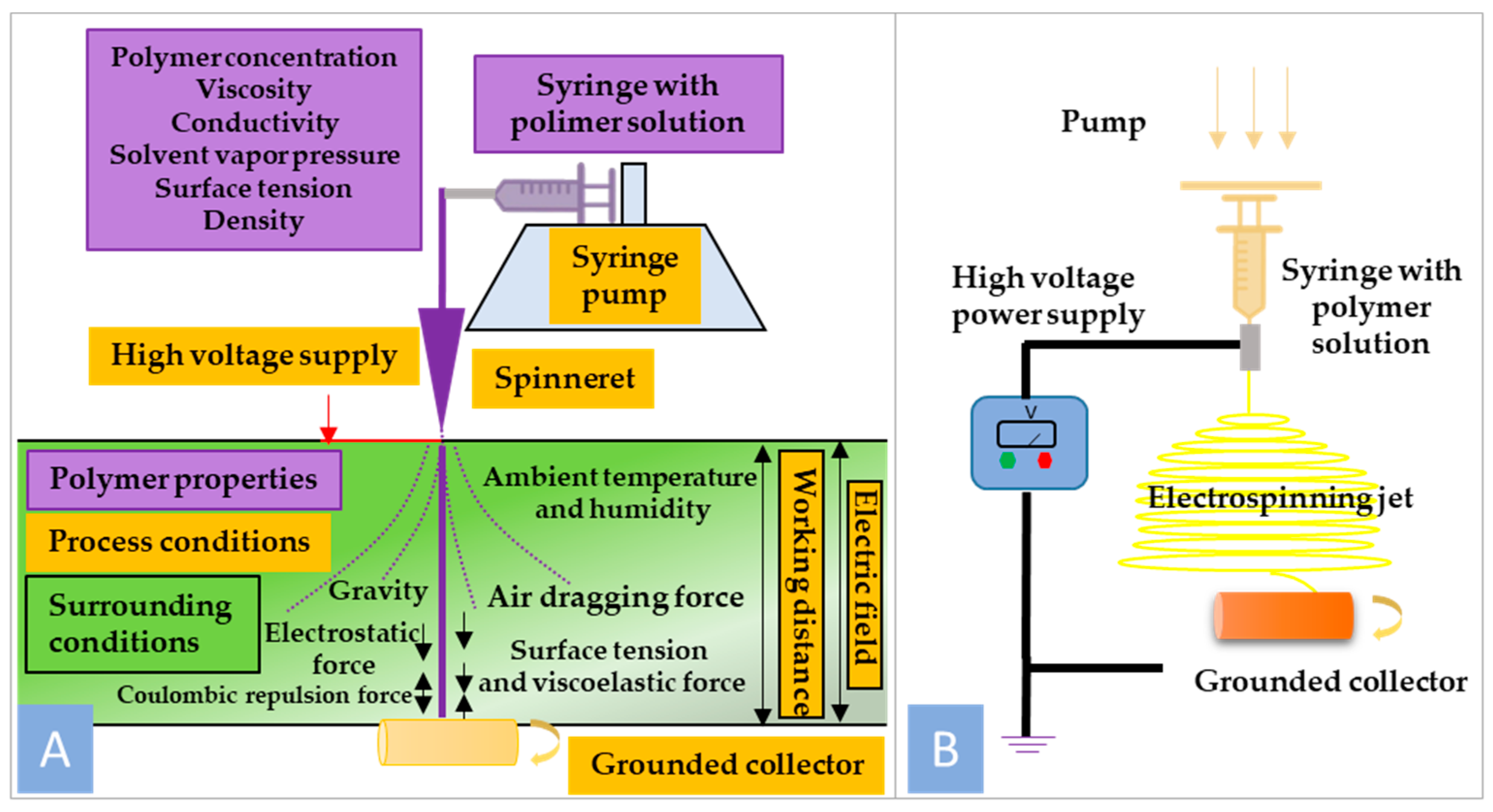
2.2. Preparation of PMMA/n-HA Solution and Scaffold Fabrication via Electrospinning Technique
2.3. Characterization of PMMA/nHA Scaffolds
2.3.1. Morphology Analysis
2.3.2. Water Contact Angle Measurements and Surface Tension Energy Determination
2.3.3. Fourier Transform Infrared Spectroscopy (FTIR)
2.3.4. Differential Scanning Calorimetry (DSC)
2.3.5. Wide Angle X-ray Scattering (WAXS)
2.3.6. In Vitro Study
2.4. Statistical Analysis
3. Results and Discussion
3.1. Morphology Analysis
3.2. Contact Angle Measurements for Surface Free Energy Determination
3.3. Fourier Transform Infrared Spectroscopy (FTIR)
3.4. Differential Scanning Calorimetry (DSC)
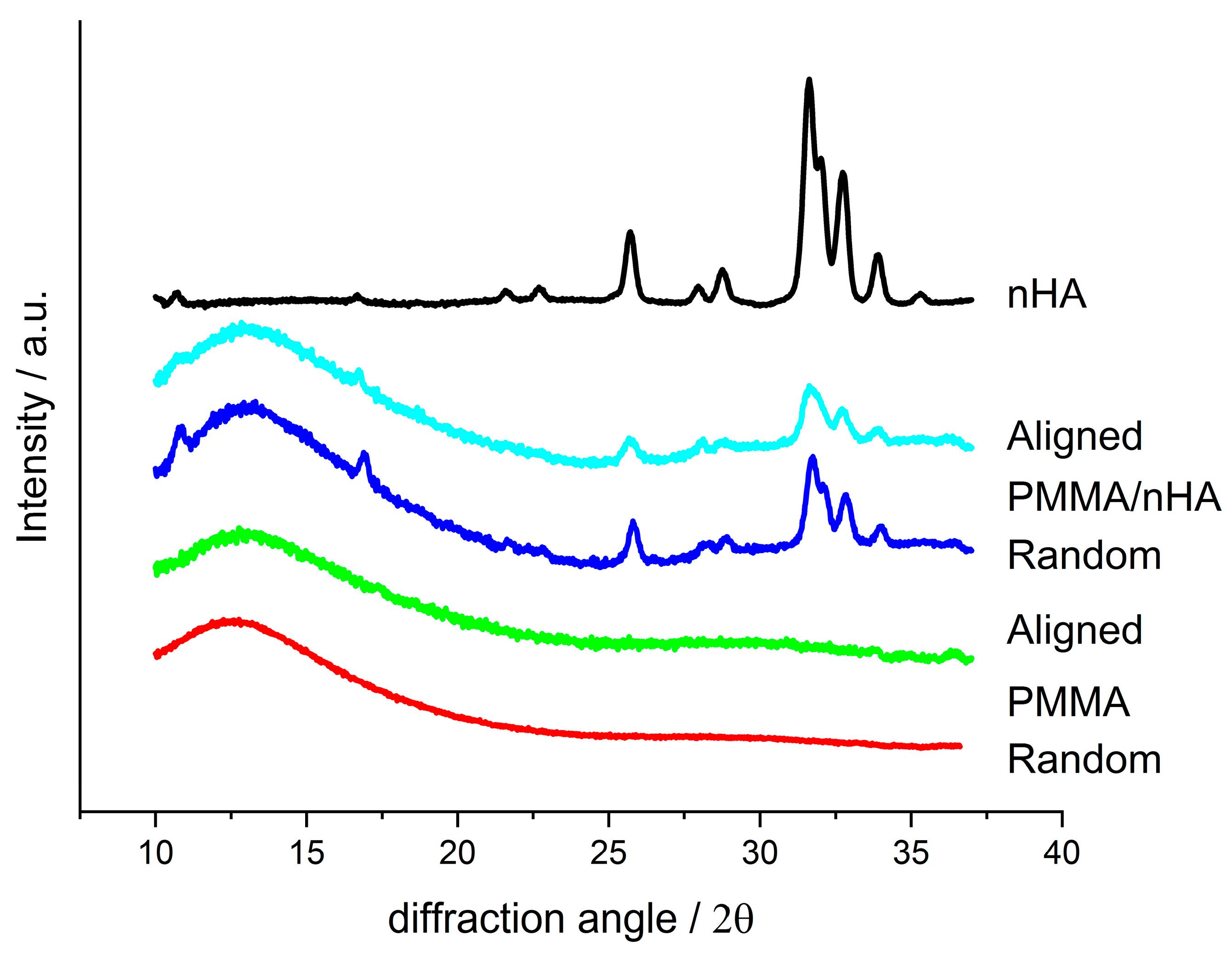
3.5. Wide Angle X-ray Scattering (WAXS)
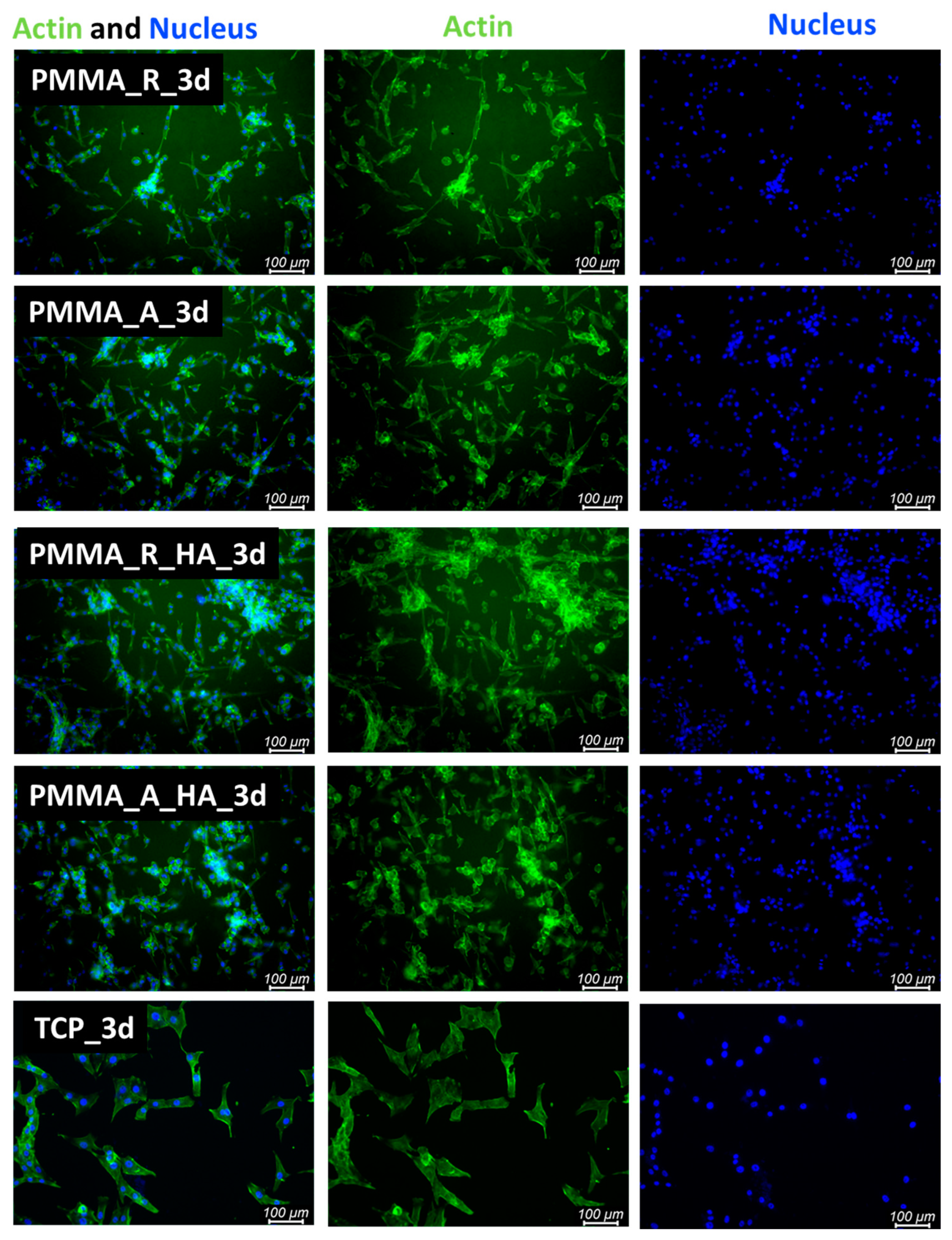
3.6. In Vitro Results
4. Conclusions
Author Contributions
Funding
Institutional Review Board Statement
Data Availability Statement
Conflicts of Interest
References
- Koons, G.L.; Diba, M.; Mikos, A.G. Materials design for bone-tissue engineering. Nat. Rev. Mater. 2020, 5, 584–603. [Google Scholar] [CrossRef]
- Esmaeili, Y.; Bidram, E.; Bigham, A.; Atari, M.; Nasr Azadani, R.; Tavakoli, M.; Salehi, S.; Mirhaj, M.; Basiri, A.; Mirzavandi, Z.; et al. Exploring the Evolution of Tissue Engineering Strategies over the Past Decade: From Cell-Based Strategies to Gene-Activated Matrix. Alex. Eng. J. 2023, 81, 137–169. [Google Scholar] [CrossRef]
- Bhumiratana, S.; Vunjak-Novakovic, G. Concise Review: Personalized Human Bone Grafts for Reconstructing Head and Face. Stem Cells Transl. Med. 2012, 1, 64–69. [Google Scholar] [CrossRef] [PubMed]
- De Long, W.G.; Einhorn, T.A.; Koval, K.; McKee, M.; Smith, W.; Sanders, R.; Watson, T. Bone Grafts and Bone Graft Substitutes in Orthopaedic Trauma Surgery: A Critical Analysis. J. Bone Jt. Surg. 2007, 89, 649–658. [Google Scholar] [CrossRef]
- Kurien, T.; Pearson, R.G.; Scammell, B.E. Bone Graft Substitutes Currently Available in Orthopaedic Practice: The Evidence for Their Use. Bone Jt. J. 2013, 95-B, 583–597. [Google Scholar] [CrossRef] [PubMed]
- Alonzo, M.; Primo, F.A.; Kumar, S.A.; Mudloff, J.A.; Dominguez, E.; Fregoso, G.; Ortiz, N.; Weiss, W.M.; Joddar, B. Bone tissue engineering techniques, advances, and scaffolds for treatment of bone defects. Curr. Opin. Biomed. Eng. 2021, 17, 100248. [Google Scholar] [CrossRef] [PubMed]
- Maia, F.R.; Bastos, A.R.; Oliveira, J.M.; Correlo, V.M.; Reis, R.L. Recent approaches towards bone tissue engineering. Bone 2022, 154, 116256. [Google Scholar] [CrossRef]
- Guo, L.; Liang, Z.; Yang, L.; Du, W.; Yu, T.; Tang, H.; Li, C.; Qiu, H. The role of natural polymers in bone tissue engineering. J. Control. Release 2021, 338, 571–582. [Google Scholar] [CrossRef]
- Ekrami, E.; Khodabandeh Shahraky, M.; Mahmoudifard, M.; Mirtaleb, M.S.; Shariati, P. Biomedical Applications of Electrospun Nanofibers in Industrial World: A Review. Int. J. Polym. Mater. Polym. Biomater. 2023, 72, 561–575. [Google Scholar] [CrossRef]
- Villarreal-Gómez, L.J.; Cornejo-Bravo, J.M.; Vera-Graziano, R.; Grande, D. Electrospinning as a Powerful Technique for Biomedical Applications: A Critically Selected Survey. J. Biomater. Sci. Polym. Ed. 2016, 27, 157–176. [Google Scholar] [CrossRef]
- Jurić, M.; Donsì, F.; Maslov Bandić, L.; Jurić, S. Natural-Based Electrospun Nanofibers: Challenges and Potential Applications in Agri-Food Sector. Food Biosci. 2023, 56, 103372. [Google Scholar] [CrossRef]
- Mamidi, N.; Velasco Delgadillo, R.M.; Gonzáles Ortiz, A.; Barrera, E.V. Carbon Nano-Onions Reinforced Multilayered Thin Film System for Stimuli-Responsive Drug Release. Pharmaceutics 2020, 12, 1208. [Google Scholar] [CrossRef] [PubMed]
- Wu, H.; Pan, W.; Lin, D.; Li, H. Electrospinning of Ceramic Nanofibers: Fabrication, Assembly and Applications. J. Adv. Ceram. 2012, 1, 2–23. [Google Scholar] [CrossRef]
- Liao, Y.; Loh, C.-H.; Tian, M.; Wang, R.; Fane, A.G. Progress in Electrospun Polymeric Nanofibrous Membranes for Water Treatment: Fabrication, Modification and Applications. Prog. Polym. Sci. 2018, 77, 69–94. [Google Scholar] [CrossRef]
- Biofabrication Methods for Reconstructing Extracellular Matrix Mimetics—ScienceDirect. Available online: https://www.sciencedirect.com/science/article/pii/S2452199X23002669 (accessed on 2 February 2024).
- Mu, J.; Luo, D.; Li, W.; Ding, Y. Multiscale Polymeric Fibers for Drug Delivery and Tissue Engineering. Biomed. Technol. 2024, 5, 60–72. [Google Scholar] [CrossRef]
- Research Progresses of Fibers in Asphalt and Cement Materials: A Review—ScienceDirect. Available online: https://www.sciencedirect.com/science/article/pii/S2097049823000021 (accessed on 2 February 2024).
- Silva, M.J.; Dias, Y.J.; Zaszczyńska, A.; Kołbuk, D.; Kowalczyk, T.; Sajkiewicz, P.Ł.; Yarin, A.L. Three-phase Bio-nanocomposite Natural-rubber-based Microfibers Reinforced with Cellulose Nanowhiskers and 45S5 Bioglass Obtained by Solution Blow Spinning. J. Appl. Polym. Sci. 2023, 140, e54661. [Google Scholar] [CrossRef]
- Silva, M.J.; Dias, Y.J.; Zaszczyńska, A.; Robles, J.R.; Abiade, J.; Kowalczyk, T.; Kołbuk, D.; Sajkiewicz, P.Ł.; Yarin, A.L. Biocomposite-based Fibrous Scaffolds of Natural Rubber/Polyhydroxybutyrate Blend Reinforced with 45S5 Bioglass Aiming at Biomedical Applications. Polym. Compos. 2023, 45, 1107–1127. [Google Scholar] [CrossRef]
- Collins, M.N.; Ren, G.; Young, K.; Pina, S.; Reis, R.L.; Oliveira, J.M. Scaffold fabrication technologies and structure/function properties in bone tissue engineering. Adv. Funct. Mater. 2021, 31, 2010609. [Google Scholar] [CrossRef]
- Jia, W.; Cui, D.; Liu, Y.; Ji, X.; Sun, M.; Cheng, Z.; Luo, Y.; Liu, G. Polyether-Ether-Ketone/Poly(Methyl Methacrylate)/Carbon Fiber Ternary Composites Prepared by Electrospinning and Hot Pressing for Bone Implant Applications. Mater. Des. 2021, 209, 109893. [Google Scholar] [CrossRef]
- Fu, Z.; Cui, J.; Zhao, B.; Shen, S.G.; Lin, K. An Overview of Polyester/Hydroxyapatite Composites for Bone Tissue Repairing. J. Orthop. Transl. 2021, 28, 118–130. [Google Scholar] [CrossRef]
- Mousa, W.F.; Kobayashi, M.; Shinzato, S.; Kamimura, M.; Neo, M.; Yoshihara, S.; Nakamura, T. Biological and Mechanical Properties of PMMA-Based Bioactive Bone Cements. Biomaterials 2000, 21, 2137–2146. [Google Scholar] [CrossRef]
- Szabelski, J.; Karpiński, R.; Krakowski, P.; Jojczuk, M.; Jonak, J.; Nogalski, A. Analysis of the Effect of Component Ratio Imbalances on Selected Mechanical Properties of Seasoned, Medium Viscosity Bone Cements. Materials 2022, 15, 5577. [Google Scholar] [CrossRef] [PubMed]
- Downes, S.; Archer, R.S.; Kayser, M.V.; Patel, M.P.; Braden, M. The Regeneration of Articular Cartilage Using a New Polymer System. J. Mater. Sci. Mater. Med. 1994, 5, 88–95. [Google Scholar] [CrossRef]
- Chand, N.; Vashishtha, S.R. Development, Structure and Strength Properties of PP/PMMA/FA Blends. Bull. Mater. Sci. 2000, 23, 103–107. [Google Scholar] [CrossRef]
- Salaeh, S.; Banda, T.; Pongdong, V.; Wießner, S.; Das, A.; Thitithammawong, A. Compatibilization of Poly(Vinylidene Fluoride)/Natural Rubber Blend by Poly(Methyl Methacrylate) Modified Natural Rubber. Eur. Polym. J. 2018, 107, 132–142. [Google Scholar] [CrossRef]
- Karatepe, U.Y.; Ozdemir, T. Improving Mechanical and Antibacterial Properties of PMMA via Polyblend Electrospinning with Silk Fibroin and Polyethyleneimine towards Dental Applications. Bioact. Mater. 2020, 5, 510–515. [Google Scholar] [CrossRef] [PubMed]
- Fuchs, K.F.; Heilig, P.; McDonogh, M.; Boelch, S.; Gbureck, U.; Meffert, R.H.; Hoelscher-Doht, S.; Jordan, M.C. Cement-Augmented Screw Fixation for Calcaneal Fracture Treatment: A Biomechanical Study Comparing Two Injectable Bone Substitutes. J. Orthop. Surg. Res. 2020, 15, 533. [Google Scholar] [CrossRef] [PubMed]
- Xue, N.; Ding, X.; Huang, R.; Jiang, R.; Huang, H.; Pan, X.; Min, W.; Chen, J.; Duan, J.-A.; Liu, P.; et al. Bone Tissue Engineering in the Treatment of Bone Defects. Pharmaceuticals 2022, 15, 879. [Google Scholar] [CrossRef] [PubMed]
- Al-Allaq, A.A.; Kashan, J.S.; Abdul-Kareem, F.M. In Vivo Investigations of Polymers in Bone Tissue Engineering: A Review Study. Int. J. Polym. Mater. Polym. Biomater. 2024, 1–16. [Google Scholar] [CrossRef]
- Varadavenkatesan, T.; Vinayagam, R.; Pai, S.; Kathirvel, B.; Pugazhendhi, A.; Selvaraj, R. Synthesis, Biological and Environmental Applications of Hydroxyapatite and Its Composites with Organic and Inorganic Coatings. Prog. Org. Coat. 2021, 151, 106056. [Google Scholar] [CrossRef]
- Sato, C.; Yamazaki, D.; Sato, M.; Takeshima, H.; Memtily, N.; Hatano, Y.; Tsukuba, T.; Sakai, E. Calcium Phosphate Mineralization in Bone Tissues Directly Observed in Aqueous Liquid by Atmospheric SEM (ASEM) without Staining: Microfluidics Crystallization Chamber and Immuno-EM. Sci. Rep. 2019, 9, 7352. [Google Scholar] [CrossRef]
- Morgan, E.F.; Gerstenfeld, L.C. The Bone Organ System: Form and Function. In Marcus and Feldman’s Osteoporosis; Elsevier: Amsterdam, The Netherlands, 2021; pp. 15–35. ISBN 978-0-12-813073-5. [Google Scholar]
- Kaviya, M.; Ramakrishnan, P.; Mohamed, S.B.; Ramakrishnan, R.; Gimbun, J.; Veerabadran, K.M.; Kuppusamy, M.R.; Kaviyarasu, K.; Sridhar, T.M. Synthesis and Characterization of Nano-Hydroxyapatite/Graphene Oxide Composite Materials for Medical Implant Coating Applications. Mater. Today Proc. 2021, 36, 204–207. [Google Scholar] [CrossRef]
- Chen, Y.; Han, P.; Vandi, L.-J.; Dehghan-Manshadi, A.; Humphry, J.; Kent, D.; Stefani, I.; Lee, P.; Heitzmann, M.; Cooper-White, J.; et al. A Biocompatible Thermoset Polymer Binder for Direct Ink Writing of Porous Titanium Scaffolds for Bone Tissue Engineering. Mater. Sci. Eng. C 2019, 95, 160–165. [Google Scholar] [CrossRef] [PubMed]
- Zaszczyńska, A.; Sajkiewicz, P.; Gradys, A.; Tymkiewicz, R.; Urbanek, O.; Kołbuk, D. Influence of Process-Material Conditions on the Structure and Biological Properties of Electrospun Polyvinylidene Fluoride Fibers. Bull. Pol. Acad. Sci. Tech. Sci. 2020, 68, 627–633. [Google Scholar] [CrossRef]
- Schindelin, J.; Arganda-Carreras, I.; Frise, E.; Kaynig, V.; Longair, M.; Pietzsch, T.; Preibisch, S.; Rueden, C.; Saalfeld, S.; Schmid, B.; et al. Fiji: An Open-Source Platform for Biological-Image Analysis. Nat. Methods 2012, 9, 676–682. [Google Scholar] [CrossRef]
- Rudawska, A.; Jacniacka, E. Analysis for Determining Surface Free Energy Uncertainty by the Owen–Wendt Method. Int. J. Adhes. Adhes. 2009, 29, 451–457. [Google Scholar] [CrossRef]
- Kleintjens, L.A. Integration of Fundamental Polymer Science and Technology; Springer Science & Business Media: Berlin/Heidelberg, Germany, 2012; ISBN 978-94-009-4185-4. [Google Scholar]
- Ginzburg, V.V. A Simple Mean-Field Model of Glassy Dynamics and Glass Transition. Soft Matter 2020, 16, 810–825. [Google Scholar] [CrossRef]
- Sheikh, F.A.; Ju, H.W.; Moon, B.M.; Park, H.J.; Kim, J.H.; Lee, O.J.; Park, C.H. A Novel Approach to Fabricate Silk Nanofibers Containing Hydroxyapatite Nanoparticles Using a Three-Way Stopcock Connector. Nanoscale Res. Lett. 2013, 8, 303. [Google Scholar] [CrossRef]
- Kołbuk, D.; Ciechomska, M.; Jeznach, O.; Sajkiewicz, P. Effect of Crystallinity and Related Surface Properties on Gene Expression of Primary Fibroblasts. RSC Adv. 2022, 12, 4016–4028. [Google Scholar] [CrossRef]
- Navarro, C.H.; Moreno, K.J.; Chávez-Valdez, A.; Louvier-Hernández, F.; García-Miranda, J.S.; Lesso, R.; Arizmendi-Morquecho, A. Friction and Wear Properties of Poly(Methyl Methacrylate)–Hydroxyapatite Hybrid Coating on UHMWPE Substrates. Wear 2012, 282–283, 76–80. [Google Scholar] [CrossRef]
- Rajendran, S.; Uma, T. Lithium Ion Conduction in PVC–LiBF4 Electrolytes Gelled with PMMA. J. Power Sources 2000, 88, 282–285. [Google Scholar] [CrossRef]
- Moreno, K.; García-Miranda, J.; Hernández-Navarro, C.; Ruiz-Guillén, F.; Aguilera-Camacho, L.; Lesso, R.; Arizmendi-Morquecho, A. Preparation and Performance Evaluation of PMMA/HA Nanocomposite as Bulk Material. J. Compos. Mater. 2015, 49, 1345–1353. [Google Scholar] [CrossRef]
- Nirmala, R.; Nam, K.T.; Park, D.K.; Woo-il, B.; Navamathavan, R.; Kim, H.Y. Structural, Thermal, Mechanical and Bioactivity Evaluation of Silver-Loaded Bovine Bone Hydroxyapatite Grafted Poly(ε-Caprolactone) Nanofibers via Electrospinning. Surf. Coat. Technol. 2010, 205, 174–181. [Google Scholar] [CrossRef]
- Bhat, K.A.; Leo Prakash, P.; Manoharan, N.; Lakshmibai, A.; Sangeetha, D. Fabrication of Polymethyl Methacrylate/Polysulfone/Nanoceramic Composites for Orthopedic Applications. J. Appl. Polym. Sci. 2013, 127, 2764–2775. [Google Scholar] [CrossRef]
- Willis, H.A.; Zichy, V.J.I.; Hendra, P.J. The Laser-Raman and Infra-Red Spectra of Poly(Methyl Methacrylate). Polymer 1969, 10, 737–746. [Google Scholar] [CrossRef]
- Dybal, J.; Štokr, J.; Schneider, B. Vibrational Spectra and Structure of Stereoregular Poly(Methyl Methacrylates) and of the Stereocomplex. Polymer 1983, 24, 971–980. [Google Scholar] [CrossRef]
- Rajendran, S.; Uma, T. Conductivity Studies on PVC/PMMA Polymer Blend Electrolyte. Mater. Lett. 2000, 44, 242–247. [Google Scholar] [CrossRef]
- Staehlke, S.; Rebl, H.; Nebe, B. Phenotypic Stability of the Human MG-63 Osteoblastic Cell Line at Different Passages. Cell Biol. Int. 2019, 43, 22–32. [Google Scholar] [CrossRef]
- Amarjargal, A.; Moazzami Goudarzi, Z.; Cegielska, O.; Gradys, A.; Kolbuk, D.; Kalaska, B.; Ruszczyńska, A.; Sajkiewicz, P. A Facile One-Stone-Two-Birds Strategy for Fabricating Multifunctional 3D Nanofibrous Scaffolds. Biomater. Sci. 2023, 11, 5502–5516. [Google Scholar] [CrossRef]
- Chang, B.; Chen, C.; Ding, S.; Chen, D.; Chang, H. Impedimetric Monitoring of Cell Attachment on Interdigitated Microelectrodes. Sens. Actuators B Chem. 2005, 105, 159–163. [Google Scholar] [CrossRef]
- Rong, Z.; Zeng, W.; Kuang, Y.; Zhang, J.; Liu, X.; Lu, Y.; Cheng, X. Enhanced Bioactivity of Osteoblast-like Cells on Poly(Lactic Acid)/Poly(Methyl Methacrylate)/Nano-Hydroxyapatite Scaffolds for Bone Tissue Engineering. Fibers Polym. 2015, 16, 245–253. [Google Scholar] [CrossRef]
- Pelipenko, J.; Kocbek, P.; Govedarica, B.; Rošic, R.; Baumgartner, S.; Kristl, J. The Topography of Electrospun Nanofibers and Its Impact on the Growth and Mobility of Keratinocytes. Eur. J. Pharm. Biopharm. 2013, 84, 401–411. [Google Scholar] [CrossRef] [PubMed]
- Xu, Z.; Li, Y.; Xu, D.; Li, L.; Xu, Y.; Chen, L.; Liu, Y.; Sun, J. Improvement of Mechanical and Antibacterial Properties of Porous nHA Scaffolds by Fluorinated Graphene Oxide. RSC Adv. 2022, 12, 25405–25414. [Google Scholar] [CrossRef] [PubMed]
- Pedone, L.; Caponetti, E.; Leone, M.; Militello, V.; Pantò, V.; Polizzi, S.; Saladino, M.L. Synthesis and Characterization of CdS Nanoparticles Embedded in a Polymethylmethacrylate Matrix. J. Colloid Interface Sci. 2005, 284, 495–500. [Google Scholar] [CrossRef][Green Version]


| Element | PMMA Aligned | PMMA Random | PMMA/nHA Aligned | PMMA/nHA Random |
|---|---|---|---|---|
| C | 61.91 ± 0.6 | 61.43 ± 0.4 | 58.42 ± 0.6 | 58.20 ± 0.7 |
| O | 38.08 ± 0.7 | 38.45 ± 0.2 | 34.80 ± 0.3 | 35.22 ± 0.5 |
| Ca | - | - | 4.93 ± 0.5 | 4.77 ± 0.7 |
| P | - | - | 1.85 ± 0.2 | 1.80 ± 0.2 |
| Other | 0.01 ± 0.001 | 0.11 ± 0.05 | - | - |
Disclaimer/Publisher’s Note: The statements, opinions and data contained in all publications are solely those of the individual author(s) and contributor(s) and not of MDPI and/or the editor(s). MDPI and/or the editor(s) disclaim responsibility for any injury to people or property resulting from any ideas, methods, instructions or products referred to in the content. |
© 2024 by the authors. Licensee MDPI, Basel, Switzerland. This article is an open access article distributed under the terms and conditions of the Creative Commons Attribution (CC BY) license (https://creativecommons.org/licenses/by/4.0/).
Share and Cite
Zaszczyńska, A.; Kołbuk, D.; Gradys, A.; Sajkiewicz, P. Development of Poly(methyl methacrylate)/nano-hydroxyapatite (PMMA/nHA) Nanofibers for Tissue Engineering Regeneration Using an Electrospinning Technique. Polymers 2024, 16, 531. https://doi.org/10.3390/polym16040531
Zaszczyńska A, Kołbuk D, Gradys A, Sajkiewicz P. Development of Poly(methyl methacrylate)/nano-hydroxyapatite (PMMA/nHA) Nanofibers for Tissue Engineering Regeneration Using an Electrospinning Technique. Polymers. 2024; 16(4):531. https://doi.org/10.3390/polym16040531
Chicago/Turabian StyleZaszczyńska, Angelika, Dorota Kołbuk, Arkadiusz Gradys, and Paweł Sajkiewicz. 2024. "Development of Poly(methyl methacrylate)/nano-hydroxyapatite (PMMA/nHA) Nanofibers for Tissue Engineering Regeneration Using an Electrospinning Technique" Polymers 16, no. 4: 531. https://doi.org/10.3390/polym16040531
APA StyleZaszczyńska, A., Kołbuk, D., Gradys, A., & Sajkiewicz, P. (2024). Development of Poly(methyl methacrylate)/nano-hydroxyapatite (PMMA/nHA) Nanofibers for Tissue Engineering Regeneration Using an Electrospinning Technique. Polymers, 16(4), 531. https://doi.org/10.3390/polym16040531