

Structure Optimization of Some Single-Ion Conducting Polymer Electrolytes with Increased Conductivity Used in “Beyond Lithium-Ion” Batteries


Abstract
1. Introduction
2. Materials and Methods
- -
- Electrolyte: single-ion conducting polymer: poly(ethylene glycol) dimethacrylate-x-styrene sulfonate (PEGDMA-SS) (denoted (1)) [1], polyurethane-trifluoromethane sulfonamide (PU-TFMSI) (denoted (2)) [11], or polydimethyl siloxane-poly(sodium1-[3-(methacryloyloxy)propylsulfonyl]-1-(trifluoromethane sulfonyl) imide-poly(ethylene glycol) methacrylate)-polydimethylsiloxane(PDMS-poly(MPA-Na+-r-PEGMA)20-PDMS10) (denoted (3)) [18]. Polymers were SIPE type, in the variant of gel polymer electrolyte. The considered solvents were: dicloro-methane (DCM, organochlorine) and tetrahydrofuran (THF) in PEGDMA-SS; benzoyl peroxide ((BzO)2. organic peroxide) and THF in PU-TFMSI, that is, dimethylformamide (DMF) and THF in PDMS-poly(MPA-Na+-r-PEGMA)20-PDMS10, respectively.
- -
- Electrodes: conversion electrodes type, as follows: for sodium-ion batteries: p-dopablepolytriphenyl amine as cathode, n-type redox-active poly(anthraquinonyl sulphide) [13,19] or redox-active organic poly(anthraquinonyl imide)s (PAQIs) [20] as anode [21]; for magnesium-ion batteries: sulfur cathodeMo6S8 [22,23]; for aluminum-ion batteries: glassy carbon/Co3S4 cathode [24].
- -
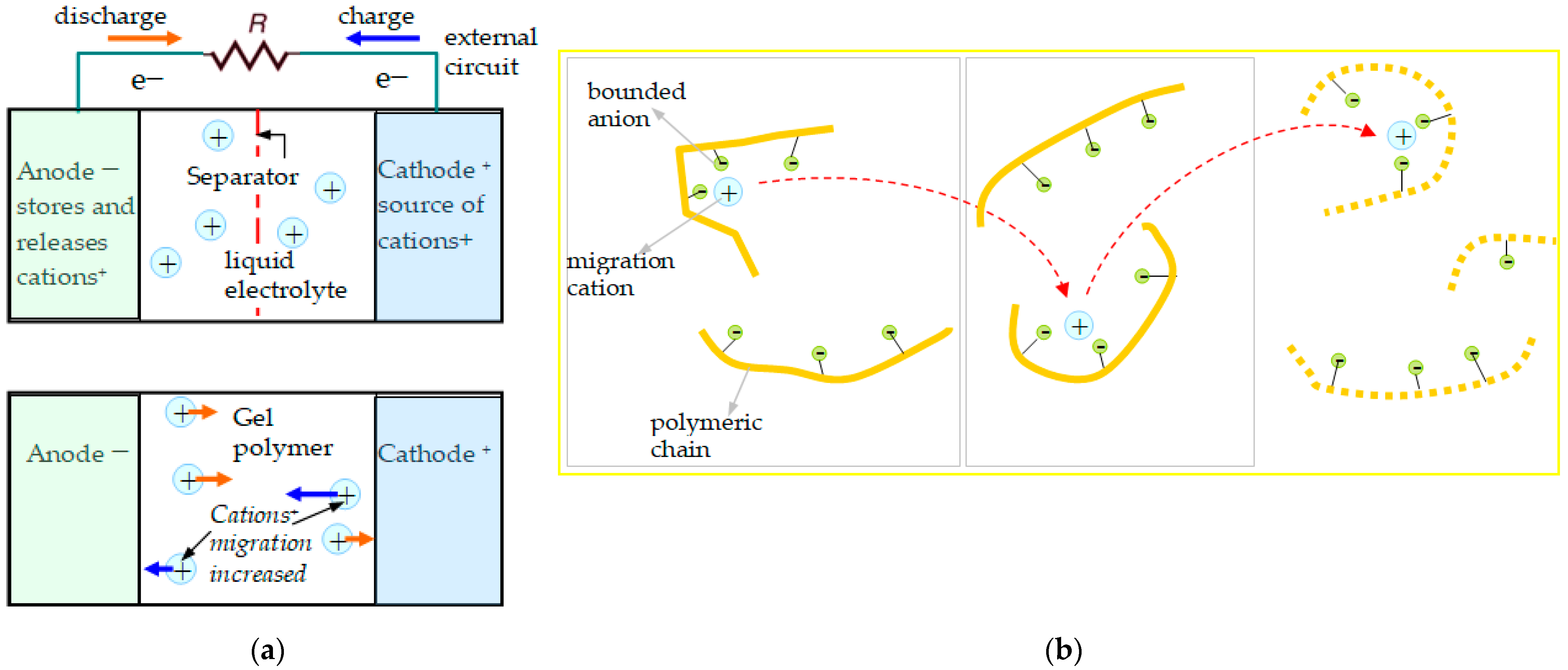
- Moving ions: ions with low electrochemical potential vs. standard hydrogen electrodes: cations: those with different valences and atomic radii, such as Na+, Mg2+, and Al3+.
3. Results for the Material Parameters
- -
- Establishing the bead groups in the polymer structure;
- -
- Calculating all the interaction forces based on the theoretical model and using data from reference values like those in the literature;
- -
- Establishing the conduction mechanism;
- -
- Determining the charge carriers’ mobility using the simulation set-up when the electrical stimuli were set;
- -
- Calculating the conductivity in the polymeric gel;
- -
- Calculating the current density;
- -
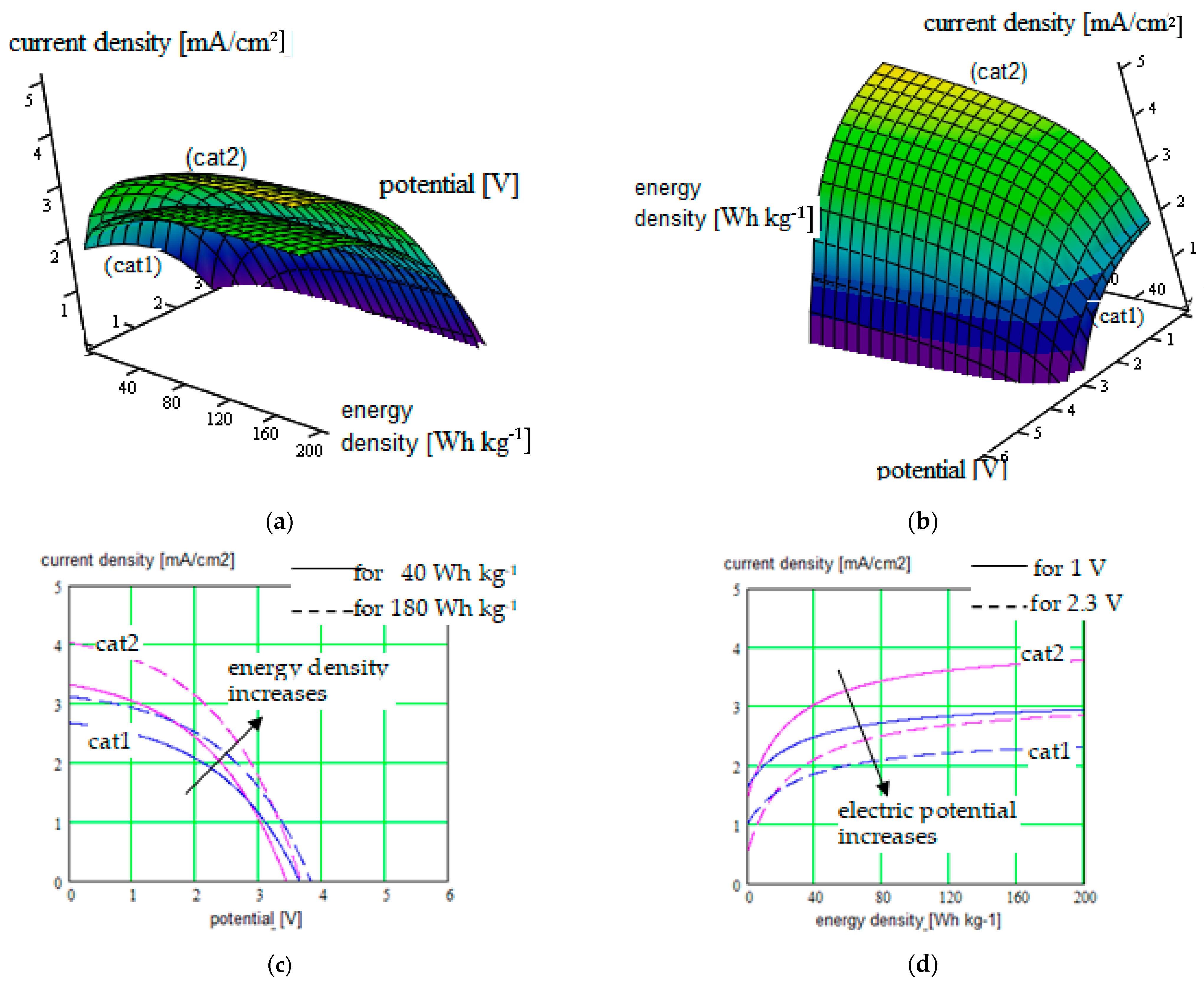
- Calculating the energy density corresponding to different electrode–electrolyte combinations;
- -
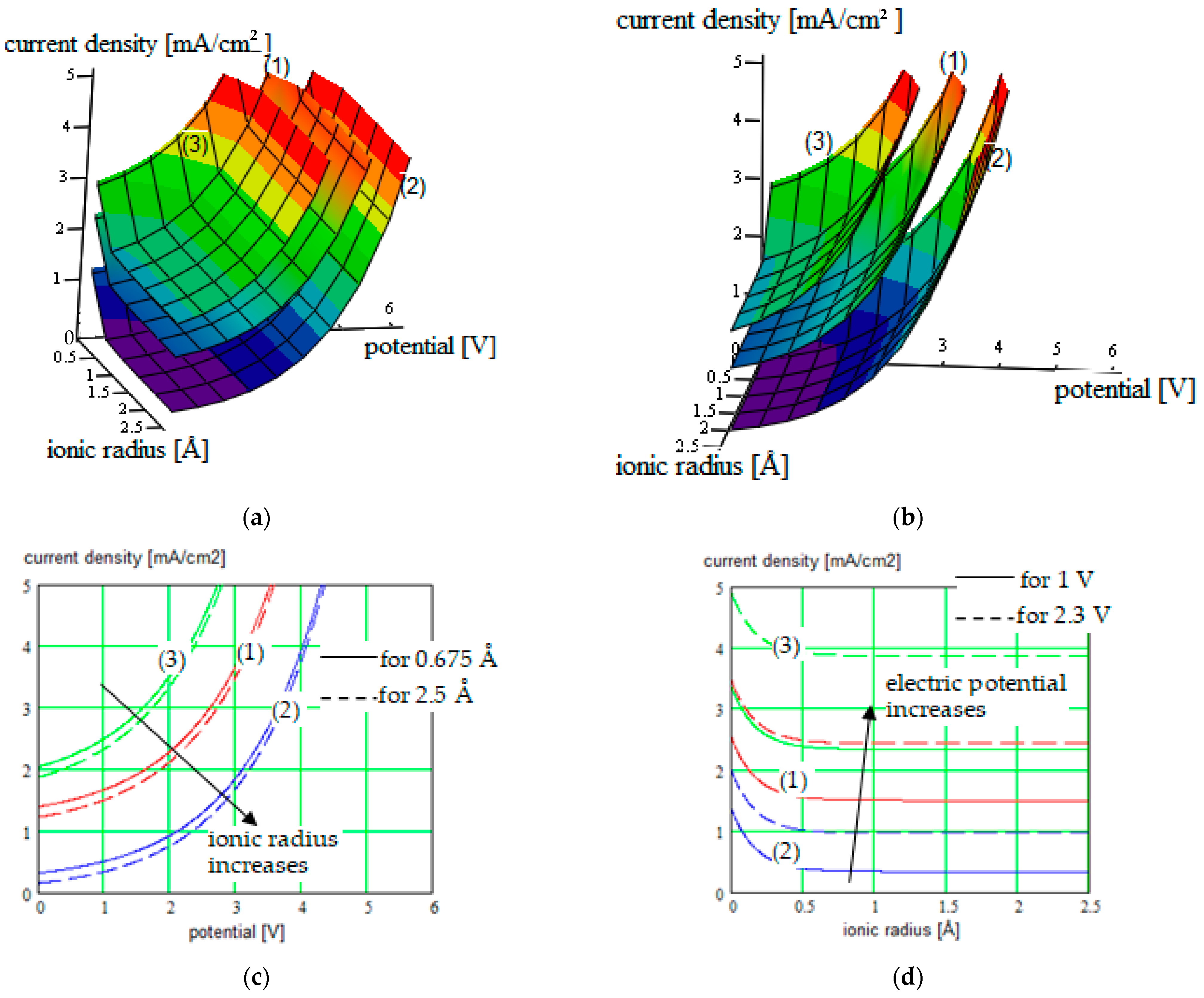
- Three-dimensional graphical representation in function of different parameters: conducting ions radius, solvent concentration in SIPE, energy density generated by the conversion electrode (correlated with the charge capacity and redox potential of the active species involved), strain and stress in the polymeric electrolyte; parameters corresponding to the beads: the bead pair distance, bonds length, bond angles, and dihedral angles; choosing of the simulation mesh; and external parameters: electric field for polymeric gel testing, temperature.
4. Conclusions
Author Contributions
Funding
Institutional Review Board Statement
Data Availability Statement
Conflicts of Interest
References
- Ford, H.O.; Cui, C.; Schaefer, J.L. Comparison of Single-Ion Conducting Polymer Gel Electrolytes for Sodium, Potassium, and Calcium Batteries: Influence of Polymer Chemistry, Cation Identity, Charge Density, and Solvent on Conductivity. Batteries 2020, 6, 11. [Google Scholar] [CrossRef]
- Nguyen, V.A.; Kuss, C. Review—Conducting Polymer-Based Binders for Lithium-Ion Batteries and Beyond. J. Electrochem. Soc. 2020, 167, 065501. [Google Scholar] [CrossRef]
- Ansari, Y. Conductive polymers for long cycle-life lithium and beyond lithium-ion batteries. In Proceedings of the International Conference and Exhibition on Polymer Chemistry, Atlanta, GA, USA, 14–16 November 2016. [Google Scholar]
- Gao, Y.; Pan, Z.; Sun, J.; Liu, Z.; Wang, J. High-Energy Batteries: Beyond Lithium-Ion and Their Long Road to Commercialization. Nano-Micro Lett. 2022, 14, 94. [Google Scholar] [CrossRef]
- Zhang, Q.; Dou, Y.; He, Q.; Deng, S.; Huang, Q.; Huang, S.; Yang, Y. Emerging Carbonyl Polymers as Sustainable ElectrodeMaterials for Lithium-Free Metal-Ion Batteries. Energy Environ. Mater. 2022, 5, 1037–1059. [Google Scholar] [CrossRef]
- Nguyen, T.K.L.; Lopez, G.; Iojoiu, C.; Bouchet, R.; Ameduri, B. Novel single-ion conducting electrolytes based on vinylidene fluoride copolymer for lithium metal batteries. J. Power Sources 2021, 498, 229920. [Google Scholar] [CrossRef]
- Kondratiev, V.V.; Holze, R. Intrinsically conducting polymers and their combinations with redox active molecules for rechargeable battery electrodes: An update. Chem. Pap. 2021, 75, 4981–5007. [Google Scholar] [CrossRef]
- Bocharova, V.; Sokolov, A.P. Perspectives for Polymer Electrolytes: A View from Fundamentals of Ionic Conductivity. Macromolecules 2020, 53, 4141–4157. [Google Scholar] [CrossRef]
- Cai, Y.; Liu, C.; Yu, Z.; Wu, H.; Wang, Y.; Ma, W.; Zhang, Q.; Jia, X. A flexible and highly conductive quasi-solid single-ion polymer electrolyte for high performance Li-metal batteries. J. Power Sources 2022, 537, 231478. [Google Scholar] [CrossRef]
- Cai, Y.; Liu, C.; Yu, Z.; Ma, W.; Jin, Q.; Du, R.; Qian, B.; Jin, X.; Wu, H.; Zhang, Q.; et al. Slidable and Highly Ionic Conductive Polymer Binder for High-Performance Si Anodes in Lithium-Ion Batteries. Adv. Sci. 2022, 10, 2205590. [Google Scholar] [CrossRef] [PubMed]
- Wang, Y.; Xie, T.; France-Lanord, A.; Berkley, A.; Johnson, J.A.; Shao-Horn, Y.; Grossman, J.C. Toward Designing Highly Conductive Polymer Electrolytes by Machine Learning Assisted Coarse-Grained Molecular Dynamics. Chem. Mater. 2020, 32, 4144–4151. [Google Scholar] [CrossRef]
- Li, Z.; Fu, J.; Zhou, X.; Gui, S.; Wei, L.; Yang, H.; Li, H.; Guo, X. Ionic Conduction in Polymer-Based Solid Electrolytes. Adv. Sci. 2023, 10, 2201718. [Google Scholar] [CrossRef]
- Zhang, D.; Meng, X.; Hou, W.; Hu, W.; Mo, J.; Yang, T.; Zhang, W.; Fan, Q.; Liu, L.; Jiang, B.; et al. Solid polymer electrolytes: Ion conduction mechanisms and enhancement strategies. Nano Res. Energy 2023, 2, e9120050. [Google Scholar] [CrossRef]
- Zhu, J.; Zhang, Z.; Zhao, S.; Westover, A.S.; Belharouak, I.; Cao, P.-F. Single-Ion Conducting Polymer Electrolytes for Solid-State Lithium–Metal Batteries: Design, Performance, and Challenges. Adv. Energy Mater. 2021, 11, 2003836. [Google Scholar] [CrossRef]
- Nguyen, D.; Tao, L.; Li, Y. Integration of Machine Learning and Coarse-Grained Molecular Simulations for Polymer Materials: Physical Understandings and Molecular Design. Front. Chem. 2022, 9, 820417. [Google Scholar] [CrossRef] [PubMed]
- Stolz, L.; Hochstädt, S.; Röser, S.; Hansen, M.R.; Martin Winter, M.; Kasnatscheew, J. Single-Ion versus Dual-Ion Conducting Electrolytes: The Relevance of Concentration Polarization in Solid-State Batteries. ACS Appl. Mater. Interfaces 2022, 14, 11559–11566. [Google Scholar] [CrossRef] [PubMed]
- Chae, W.; Kim, B.; Won Sun Ryoo, W.S.; Earmme, T. A Brief Review of Gel Polymer Electrolytes Using In Situ Polymerization for Lithium-ion Polymer Batteries. Polymers 2023, 15, 803. [Google Scholar] [CrossRef] [PubMed]
- Hoang Huy, V.P.; So, S.; Hur, J. Inorganic Fillers in Composite Gel Polymer Electrolytes for High-Performance Lithium and Non-Lithium Polymer Batteries. Nanomaterials 2021, 11, 614. [Google Scholar] [CrossRef] [PubMed]
- Dehghani, E.; Salami-Kalajahi, M.; Moghaddam, A.R.; Roghani-Mamaqani, H. In Situ Dendrimer-Crosslinked Gel Polymer Electrolytes for Lithium-Ion Batteries with High Ionic Conductivity and Excellent Electrochemical Performance. ACS Appl. Polym. Mater. 2022, 4, 4154–4165. [Google Scholar] [CrossRef]
- Mukherjee, S.; Bin Mujib, S.; Soares, D.; Singh, G. Electrode Materials for High-Performance Sodium-Ion Batteries. Materials 2019, 12, 1952. [Google Scholar] [CrossRef]
- Quartarone, E.; Mustarelli, P. Electrolytes for solid-state lithium rechargeable batteries: Recent advances and perspectives. Chem. Soc. Rev. 2011, 40, 2525–2540. [Google Scholar] [CrossRef]
- Ye, H.; Xian, W.; Li, Y. Machine Learning of Coarse-Grained Models for Organic Molecules and Polymers: Progress, Opportunities, and Challenges. ACS Omega 2021, 6, 1758–1772. [Google Scholar] [CrossRef]
- Wang, J.; Han, Y.; Xu, Z.; Yang, X.; Ramakrishna, S.; Liu, Y. Dissipative Particle Dynamics Simulation: A Review on Investigating Mesoscale Properties of Polymer Systems. Macromol. Mater. Eng. 2021, 306, 2000724. [Google Scholar] [CrossRef]
- Santo, K.P.; Neimark, A.V. Dissipative particle dynamics simulations in colloid and Interface science: A review. Adv. Colloid Interface Sci. 2021, 298, 102545. [Google Scholar] [CrossRef] [PubMed]
- Zhang, B.; Guan, B.; Liu, W.; Peng, B.; Cong, S. Dissipative Particle Dynamics Simulation and Microscopic Experimental Study of Emulsification Performance of Surfactant/Polymer Flooding. Processes 2023, 11, 1411. [Google Scholar] [CrossRef]
- Wei, T.; Ren, C. Cap. 6—Theoretical simulation approaches to polymer research. In Polymer Science and Innovative Applications; AlMaadeed, M.A.A., Ponnamma, D., Carignano, M.A., Eds.; Elsevier: Amsterdam, The Netherlands, 2020; pp. 207–228. [Google Scholar]
- Gao, Y.; Qu, F.; Wang, W.; Li, F.; Zhao, X.; Zhang, L. Increasing the electrical conductivity of polymer nanocomposites under the external field by tuning nanofiller shape. Compos. Sci. Technol. 2019, 176, 37–45. [Google Scholar] [CrossRef]
- Shahrim, N.A.A.; Ahmad, Z.; Azman, A.W.; Buys, Y.F.; Sarifuddin, N. Mechanisms for doped PEDOT:PSS electrical conductivity improvement. Mater. Adv. 2021, 2, 7118–7138. [Google Scholar] [CrossRef]
- Dixit, M.B.; Anand Parejiya, A.; Muralidharan, N.; Essehli, R.; Amin, R.; Belharouak, I. Understanding Implications of Cathode Architecture on Energy Density of Solid-State Batteries. Energy Storage Mater. 2021, 40, 239–249. [Google Scholar] [CrossRef]
- Dixit, M.; Parejiya, A.; Essehli, R.; Muralidharan, N.; Haq, S.U.; Amin, R.; Belharouak, I. SolidPAC is an interactive battery-on-demand energy density estimator for solid-state batteries. Cell Rep. Phys. Sci. 2022, 3, 100756. [Google Scholar] [CrossRef]
- Wang, L.; Li, Z.; Meng, Z.; Xiu, Y.; Dasari, B.; Zhao-Karger, Z.; Fichtner, M. Designing Gel Polymer Electrolyte with Synergetic Properties for Rechargeable Magnesium Batteries. Energy Storage Mater. 2022, 48, 155–163. [Google Scholar] [CrossRef]
- Wang, L.; Jankowski, P.; Njel, C.; Bauer, W.; Li, Z.; Meng, Z.; Dasari, B.; Vegge, T.; Lastra, J.M.G.; Zhao-Karger, Z.; et al. Dual Role of Mo6S8 in Polysulfide Conversion and Shuttle for Mg–S Batteries. Adv. Sci. 2022, 9, 2104605. [Google Scholar] [CrossRef]
- Li, H.; Yang, H.; Sun, Z.; Shi, Y.; Cheng, H.-M.; Li, F. A Highly Reversible Co3S4 Microsphere Cathode Material for Aluminum-Ion Batteries. Nano Energy 2019, 56, 100–108. [Google Scholar] [CrossRef]
- Cao, P.-F.; Li, B.; Yang, G.; Zhao, S.; Townsend, J.; Xing, K.; Qiang, Z.; Vogiatzis, K.D.; Sokolov, A.P.; Nanda, J.; et al. Elastic Single-Ion Conducting Polymer Electrolytes: Toward a Versatile Approach for Intrinsically Stretchable Functional Polymers. Macromolecules 2020, 53, 3591–3601. [Google Scholar] [CrossRef]
- Deng, W.; Liang, X.; Wu, X.; Qian, J.; Cao, Y.; Ai, X.; Feng, J.; Yang, H. A low cost, all-organic Na-ion battery based on polymeric cathode and anode. Sci. Rep. 2013, 3, 2671. [Google Scholar] [CrossRef] [PubMed]
- Bao, J.; Shi, G.; Tao, C.; Whang, C. Polycarbonate-based polyurethane as a polymer electrolyte matrix for all-solid-state lithium batteries. J. Power Sources 2018, 389, 84–92. [Google Scholar] [CrossRef]


| SIPE | Clusters Chemical Structure |
|---|---|
| PEGDMA-SS (1) | 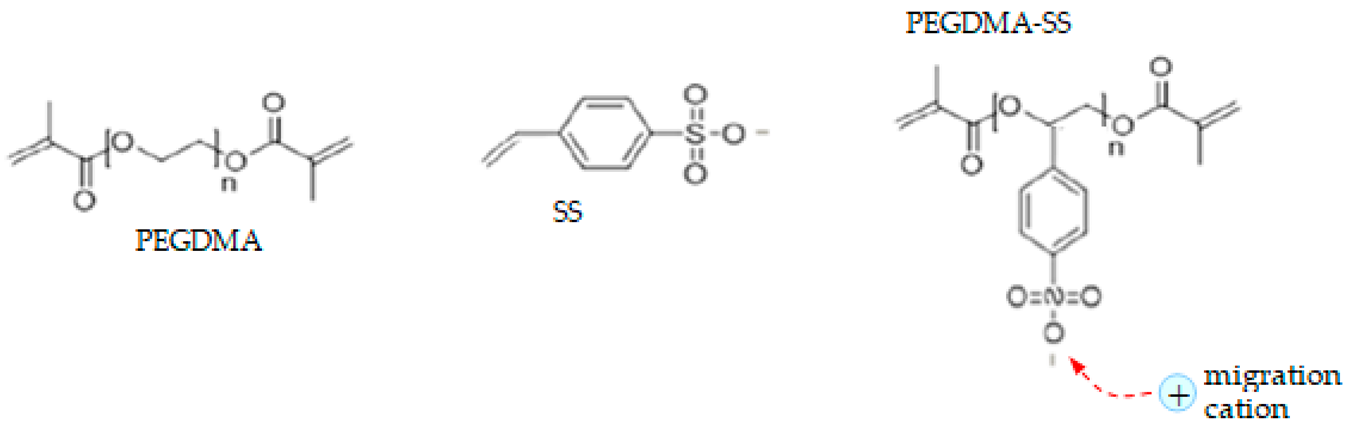 |
| PU-TFMSI (2) |  |
| PDMS-poly(MPA-Na+-r-PEGMA)20-PDMS10 (3) | 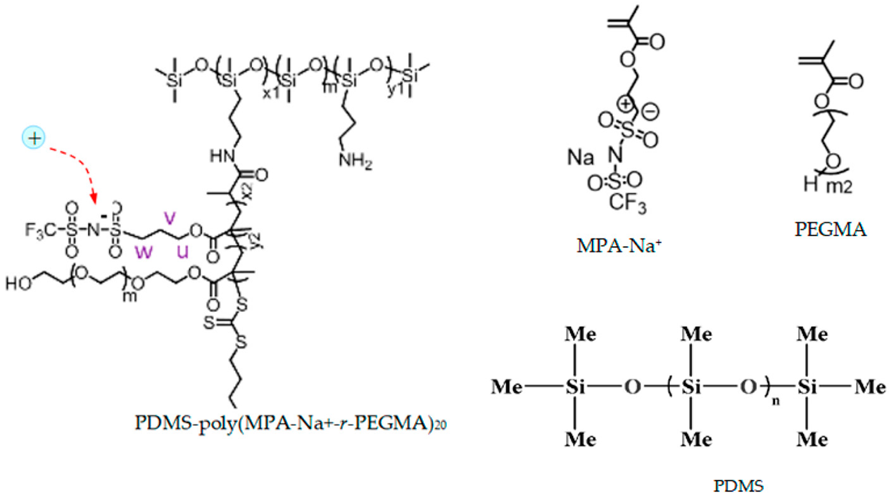 |
| Material: Electrolyte + Solvent | Current or Current Density [mA/cm2]/Obtained Electric Potential [V] | Control Parameters | Applications/Characteristics | Method of Determination/Source |
|---|---|---|---|---|
| /Conversion Electrodes | ||||
| PEGDMA-SS (1) + diglyme (DEG), tetraglyme (TEG), or ethylene carbonate + propylene carbonate (EC:PC) | Reported in the literature: | |||
| −40 A to 20 A/ | Solvent nature and concentration Cation nature (K+, Na+, Ca2+) Charge density of CP Swelling state of CP Temperature (−20 °C–115 °C) | “Beyond lithium-ion” batteries /Rechargeable; solid CP electrolyte, solid CP gel electrolyte; high energy density | Experimental:
| |
| −4 V to 3 V | ||||
| for Na+ batteries (solvent DEG) | ||||
| −5 A to 4 A/ | ||||
| −4 V to 6 V | ||||
| for Ca2+ batteries (solvent DEG) | ||||
| −160 A to 140 A/ | ||||
| −4 V to 3 V | ||||
| for Na+ batteries (solvent EC:PC) | Polymer samples:1/4” (6.35 mm) diameter pieces | Ford &, 2020 [1] | ||
| Our method: | ||||
| PEGDMA-SS (1) + DCM or THF | 1.2 to 5.2 mA/cm2/0 V to 3.6 V |
| similar | Structure description: (CGMD) model combined with the atomistic model; (DPD) model—for conductivity determination; Simulation (HFSS: Ansys HFSS 2022 R1, Mathcad: PTC Mathcad Prime 9) |
Correlated parameters: electric potential & ionic radius | ||||
| 0 to 4.6 mA/cm2/0 V to 3.9 V Correlated parameters: electric potential & solvent concentration | |||
| Electrode thickness = 400 μm, particles inside on the order of micrometers | ||||
| Material: Electrolyte + Solvent | Current or Current Density [mA/cm2]/Obtained Electric Potential [V] | Control Parameters | Applications/Characteristics | Method of Determination/Source |
| /Conversion Electrodes | ||||
| PU-TFMSI (2) + (BzO)2 or THF | Reported in the literature: | |||
| Swollen ratio | Flexible batteries and wearable devices; /Excellent mechanical performance; Electrochemical stability | Spectral analysis, H NMR spectra (Bruker AVANCE 400MHz III spectrometer, Brucker Optics, Leipzig, Germany); Infrared radiation spectra (Nicolet™ iS™ 10 FT-IR-Spectrometer—Thermo Fisher Scientific, Waltham, MA, USA); Mechanical tensile-stress (Instron 5944 Microtester, Instron, Norwood, MA, USA); Differential scanning calorimetry (Pyris 1 DSC—PerKin Elmer, Shelton, CT, USA); Thermogravimetric analysis (ASAP2020-Netzsch, Micromeritics, Norcross, GA, USA); X-ray Diffraction (X’TRA—Thermo Fisher Scientific, USA); SEM (Hitachi Model S-3400N Variable-Pressure SEM, Hitachi—Science & Technology, Berkshire, UK); X-ray photoelectron Spectrometry (PHI 5000 VersaProbe III, ULVAC-PHI, Inc., Hagisono, Chigasaki, Kanagawa, Japan) | ||
| Temperature | ||||
| 0 to 0.7 mA/cm2/5 V to 6.5 V | PU-TFMSI membranes (2 mm × 35 mm) Cathode (LFP)/Li anode | |||
| Cai &, 2022 [11,15] | ||||
| Our method: | ||||
| PU-TFMSI (2) + (BzO)2 or THF | 0.1 to 5.1 mA/cm2/0 V to 4.3 V |
| similar | Structure description: (CGMD) model combined with the atomistic model; (DPD) model—for conductivity determination; Simulation (HFSS: Ansys HFSS 2022 R1, Mathcad: PTC Mathcad Prime 9) |
Correlated parameters: electric potential & ionic radius | ||||
| 0 to 4.95 mA/cm2/0 V to 4.25 V Correlated parameters: electric potential & solvent concentration | |||
| Electrode thickness = 400 μm, particles inside on the order of micrometers | ||||
| Material: Electrolyte + Solvent | Current or Current Density [mA/cm2]/Obtained Electric Potential [V] | Control Parameters | Applications/Characteristics | Method of Determination/Source |
| /Conversion Electrodes | ||||
| PDMS-poly(MPA-Na+-r-PEGMA)20-PDMS10 (3) + DMF or THF | Reported in the literature: | |||
| 1.6 to 2.3 mA/cm2/3.8 V to 2.5 V | Monomer nature | Stretchable batteries/electronics Stretchable functional polymeric materials /Elastic SIPEs | Spectral analysis, H NMR spectra (Bruker AVANCE 400MHz III spectrometer, Brucker Optics, Leipzig, Germany); SEM (Hitachi Model S-3400N Variable-Pressure SEM, Hitachi—Science & Technology, Berkshire, UK); Energy Dispersive X-ray Spectroscopy (Spectra 200 TEM, Thermo Fisher Scientific Inc., Waltham, MA USA); Differential scanning calorimetry (Pyris 1 DSC—PerKin Elmer, Shelton, CT, USA); Broadband dielectric spectroscopy (BDS) (Novocontrol BDS Concept 80, Novocontrol Technologies, Montabaur, Germany) Galvanostatic test Gel Permeation Chromatography (GPC) (1260 Infinity II LC System, Agilent, Santa Clara, CA, USA) Atomic adsorption spectroscopy (AAS) (Routine Analyzer novAA 800, Analytik Jena, Jena, Germany) | |
| Molar ratio of PDMS and grafted block copolymers | ||||
| Temperature | ||||
| Frequency | ||||
| Polymer membranes (5.0 mm × 4.0 cm) | ||||
| Cao &, 2020 [18] | ||||
| Our method: | ||||
| PDMS-poly(MPA-Na+-r-PEGMA)20-PDMS10 (3) + DMF or THF | 1.9 to 5.8 mA/cm2/0 V to 2.8 V Correlated parameters: electric potential & ionic radius |
| similar | Structure description: (CGMD) model combined with the atomistic model; (DPD) model—for conductivity determination; Simulation (HFSS: Ansys HFSS 2022 R1, Mathcad: PTC Mathcad Prime 9) |
| Correlated parameters: electric potential & ionic radius | ||||
| 0 to 3.5 mA/cm2/0 V to 3 V Correlated parameters: electric potential & solvent concentration | |||
| Electrode thickness = 400 μm, particles inside on the order of micrometers | ||||
Disclaimer/Publisher’s Note: The statements, opinions and data contained in all publications are solely those of the individual author(s) and contributor(s) and not of MDPI and/or the editor(s). MDPI and/or the editor(s) disclaim responsibility for any injury to people or property resulting from any ideas, methods, instructions or products referred to in the content. |
© 2024 by the authors. Licensee MDPI, Basel, Switzerland. This article is an open access article distributed under the terms and conditions of the Creative Commons Attribution (CC BY) license (https://creativecommons.org/licenses/by/4.0/).
Share and Cite
Butnicu, D.; Ionescu, D.; Kovaci, M. Structure Optimization of Some Single-Ion Conducting Polymer Electrolytes with Increased Conductivity Used in “Beyond Lithium-Ion” Batteries. Polymers 2024, 16, 368. https://doi.org/10.3390/polym16030368
Butnicu D, Ionescu D, Kovaci M. Structure Optimization of Some Single-Ion Conducting Polymer Electrolytes with Increased Conductivity Used in “Beyond Lithium-Ion” Batteries. Polymers. 2024; 16(3):368. https://doi.org/10.3390/polym16030368
Chicago/Turabian StyleButnicu, Dan, Daniela Ionescu, and Maria Kovaci. 2024. "Structure Optimization of Some Single-Ion Conducting Polymer Electrolytes with Increased Conductivity Used in “Beyond Lithium-Ion” Batteries" Polymers 16, no. 3: 368. https://doi.org/10.3390/polym16030368
APA StyleButnicu, D., Ionescu, D., & Kovaci, M. (2024). Structure Optimization of Some Single-Ion Conducting Polymer Electrolytes with Increased Conductivity Used in “Beyond Lithium-Ion” Batteries. Polymers, 16(3), 368. https://doi.org/10.3390/polym16030368