1. Introduction
Brain–computer interface (BCI) technology is a cutting-edge interdisciplinary area combining neuroscience, computer science, and engineering to establish a direct connection between the human brain and external devices. With the rapid development of neuroscience and computer science, BCI technology provides new ways for people to explore direct interaction with computers or other intelligent devices [
1].
In the medical field, embedded brain–computer interface technology is of great significance. For patients who have lost their motor abilities due to brain injury, amputation, or neurological disorders, BCI technology offers a path of hope [
2]. By recording and analyzing brain activity, BCI can convert brain signals into commands that control assistive devices such as prosthetic limbs or exoskeletons [
3]. These applications can help patients regain some motor function and improve quality of life and autonomy.
In neuroscience research, embedded brain–computer interface technology shows great potential for development. By directly recording brain activities, scientists can gain a deeper understanding of human brain functions and cognitive processes [
4]. BCI technology helps neuroscientists decipher the brain’s information-processing mechanisms, which can lead to in-depth studies of complex neural behaviors such as memory, learning, and decision-making [
5,
6,
7].
In brain–computer interfaces, a microelectrode array is a set of tens to hundreds of micrometer-sized electrodes that are implanted or attached directly to the surface of the cerebral cortex to capture electrical signals from the brain by recording neuronal activity. The rigidity of the electrodes and the flexibility of the mesh substrate allow them to penetrate tissues and fit tightly to the brain surface to effectively capture neural signals [
8]. However, long-term electrode stability and variability are key challenges in BCI research and clinical applications [
9].
A Utah array consists of a set of tiny electrodes that are precisely implanted in specific areas of the cerebral cortex by microsurgery, enabling the real-time recording and monitoring of neuronal electrical activity and capturing subtle changes in the brain [
10]. In addition, microelectrode insertion sites can modulate inflammation, promote neuroprotection, and improve performance over time [
11].
Brain–computer interface implantation is a complex and challenging task involving the implantation of electrodes or other sensors into the brain to capture neural signals and enable interaction with external devices [
12]. In-mold electronics (IME), an emerging fabrication technology, meets the needs of Utah arrays by combining printed electronic components with thin-film insertion molding to fabricate highly integrated, small-sized electronic devices [
13,
14].
The occurrence of joint displacement is closely related to the flow behavior in the injection molding process, the pressure distribution in the pressure holding stage, the shrinkage in the cooling process and the mold design. In the process of filling the mold cavity with molten plastic, factors such as the flow speed of the plastic, shear stress, and pressure distribution will exert forces on the embedded node, and if these forces exceed the fixed force of the node, it may cause the node to shift. The pressure in the holding stage is also an important factor affecting the displacement of the node, and a too high or uneven holding pressure will further aggravate the movement of the node. In addition, the uneven shrinkage caused by the different cooling rates in different regions during the cooling process will also cause slight displacement of the nodes.
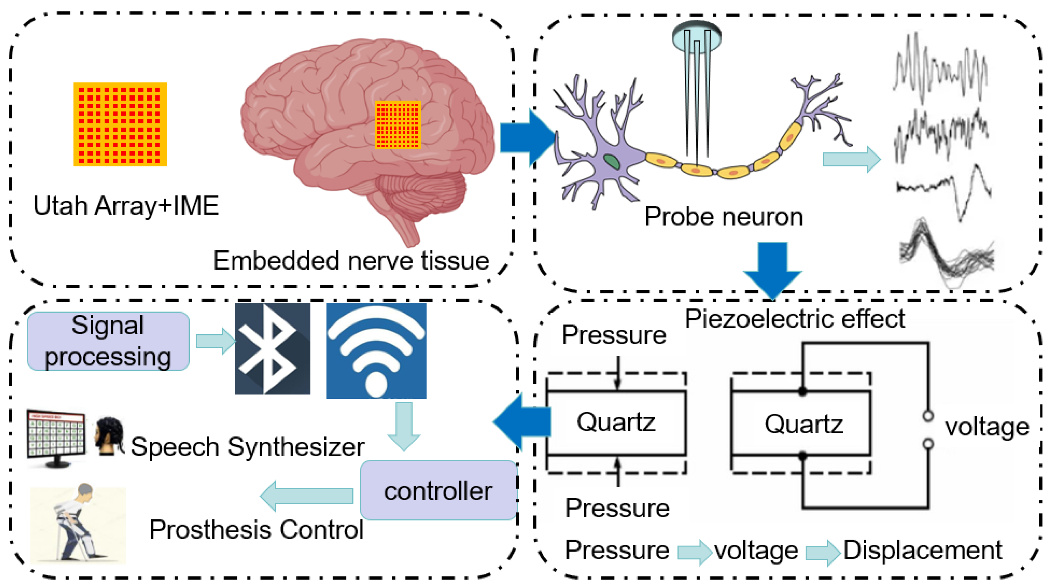
The realization process of the brain–computer interface is shown in
Figure 1. As technology advances and application requirements increase, the focus of research has gradually shifted to improving the performance, stability and user experience of the system. It is now more important to focus on the stability of the signal transmission as well as the stability of the received wave to ensure that the node displacement of the brain–computer interface remains within a small range. From the perspective of practical application, stable node displacement can effectively reduce the interference and loss in the signal transmission process and ensure the accuracy and stability of the brain–computer interface signal. In the application of the brain–computer interface, maintaining a small node displacement can help reduce signal noise, improve signal transmission efficiency, and ensure that the received brain waves and neural signals can accurately reflect the activity state of the brain.
Therefore, this paper focuses on the node displacement problem and explores methods and techniques to reduce node displacement by optimizing injection molding parameters. Although there are many other important research directions in the field of BCI, such as the improvement of signal-processing algorithms and the enhancement of hardware performance, the node displacement problem, as one of the core problems affecting the stability and accuracy of the system, is the basis for realizing an efficient and stable BCI system.
In the second section, a literature review of related research methods will be conducted to analyze the results and shortcomings of existing studies. The third section describes the materials and methods used in this paper, including the specific principles and formula derivation. The fourth section describes in detail the experimental program and the process of simulation. The fifth section describes and analyzes the result graphs obtained for the experiments and simulations. The last section summarizes the main conclusions of the research in this paper and discusses its significance and potential applications.
2. Literature Review
The focus of this paper is on the use of in-mold electronics (IME) to mold Utah arrays for the efficient manufacturing of brain–computer interfaces. IME technology allows for the simultaneous fabrication of electronic components and plastic housings during the molding process by embedding the conductive materials and functional components directly into the injection mold. This approach significantly improves product integration and performance while reducing manufacturing costs and complexity.
In this process, it is important to ensure precise node displacement in order to guarantee the quality of the lines in the film. Node displacement on the surface of the film is one of the key aspects of the entire signal transmission process, as the displacement of the line nodes directly affects the stability and accuracy of the signal transmission.
Figure 1 shows the implementation of BCI, where when a piezoelectric sensor is used for signal transmission, small mechanical vibrations caused by neuronal activity result in node displacements on the surface of the film. These displacements are a product of the piezoelectric effect, which converts mechanical energy into electrical energy. Therefore, the accuracy and controllability of the initial node displacements directly determines the strength, stability and resolution of the signal. Therefore, the control of node displacement is crucial.
Brain–computer interface technology is currently in a rapid development stage and has made many impressive achievements. However, the technology still faces many challenges, one of which is that the node displacements of lines in microelectrode arrays can directly affect the quality of signal transmission and the stability of the device [
15]. Nodal displacement of a line segment is the physical positional displacement of the line segment connection points due to material flow, cooling, and curing during the injection molding process. To ensure the minimum node displacement within the wire segment, the node displacement is optimized by adjusting the key parameters in the injection molding process.
Injection molding is a common manufacturing process used to heat thermoplastics to a molten state, then inject them into a mold and ultimately cool them for molding. During this process, the control of injection molding parameters has a significant impact on the quality and performance of the final product, especially for small electronic devices [
16]. In the injection molding process, the precise control of process parameters is critical to product quality. Studies have shown that key parameters of injection molding, such as melt temperature, holding pressure, holding time, and cooling rate, have a direct impact on the physical properties and final quality of molded parts [
17]. In recent years, many studies have focused on optimizing these parameters to reduce molding defects such as bubbles, warping, and shrink marks, and to improve the mechanical strength and surface finish of the products.
Especially in the high precision and complex geometries of molded parts, small parameter adjustments may also lead to significant quality differences [
18]. Therefore, how to optimize the process through precise parameter control has become an important research direction to improve the stability of the injection molding process and product consistency [
19]. These studies have further emphasized the importance of multiparameter optimization methods, proving that the residual stresses can be effectively reduced and the nodal displacements can be reduced through reasonable parameter combinations, thus significantly improving the overall performance of the molded parts [
20].
There are many methods to optimize the injection molding parameters, such as applying a wavelet analysis to noise reduction and the feature extraction of the cavity pressure/holding pressure curves of injection molding machines, as well as identifying and optimizing the molding process parameters using a variety of recognizable performance evaluation methods [
21]. Optimization techniques combining orthogonal tests, Kriging models and optimization algorithms can also be utilized. Kriging models are established using four types of correlation functions that affect the accuracy of the model, and the model with higher accuracy is selected [
22]. The multi-objective optimization of the injection process can also be achieved by combining the Latin Hypercubic Sampling method with Constraint Generation Inverse Design Network (CGIDN) [
23]. In optimizing the injection molding parameters, the NSGA-II algorithm was combined with a prediction model to obtain the Pareto optimal solution using the Kriging model [
24]. A multi-objective robust optimization method using the Bayesian and Kriging models considering key metrics is used to study the deformation and temperature of plastic parts [
25]. Among these optimization methods, the Kriging model is widely used in injection molding parameter optimization with its unique advantages. The Kriging model can provide very accurate prediction results. During the injection molding process, the accurate prediction of the effects of each parameter on the node displacement and other performance indexes helps to find the optimal parameter combination. Therefore, the Kriging model is chosen to optimize the injection molding parameters in this paper.
In order to find a more optimal combination of injection molding parameters, physically informative neural-network sparse regression control partial differential equations (PDEs) have good effectiveness and robustness [
26]. A stochastic discretization method is used to optimize the PDE discretization for adaptive sparse mesh structures. The sparse regression of physically informative neural networks is used to control partial differential equations from sparse and noisy data in nonlinear spatiotemporal systems, proving the effectiveness and robustness of the method [
27]. Deep-neural-network (DNN)-based methods can be used to enhance the scenarios of PDE systems using experimental data [
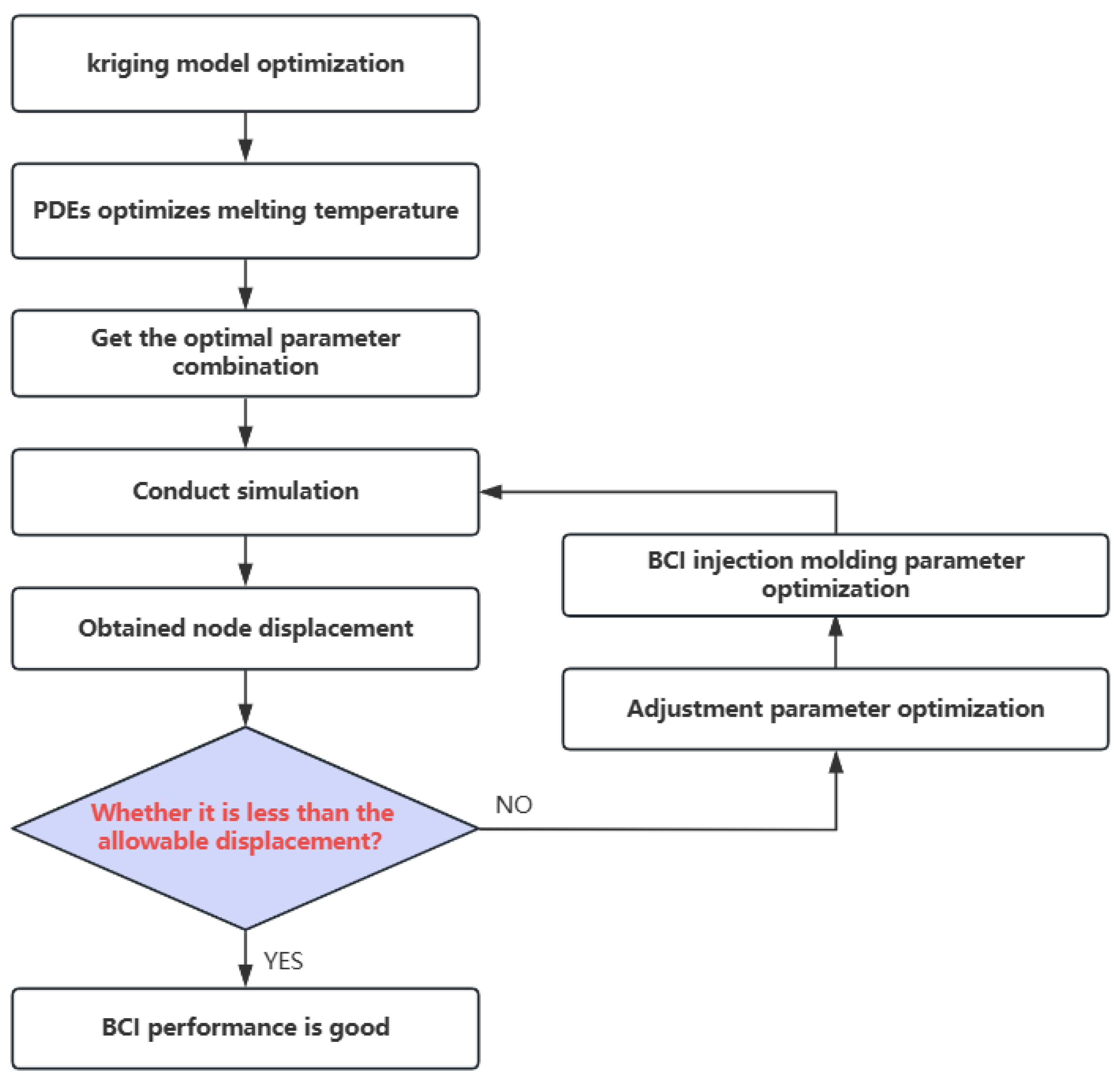
28]. A combination of Kriging and partial differential equations was used to optimize the injection molding parameters to reduce node displacement. The effects of key factors on node displacement were analyzed using the Kriging model, which provided an important reference for optimizing the injection molding parameters. Meanwhile, the application of PDEs method further analyzes the heat transfer during the injection molding process in depth, providing a more comprehensive perspective for accurately determining the optimal injection molding parameters. The optimized parameters with minimum node displacements are finally determined, providing a reliable guarantee for stable signal transmission in applications such as brain–computer interfaces. The PDEs are capable of describing in detail the heat transfer and flow behaviors of the material during the injection molding process. The partial differential equation analysis can accurately simulate the flow state and solidification process of the material in the mold at different melting temperatures, thus evaluating the effect of temperature on the nodal displacement and the quality of the finished product. Therefore, the partial differential equation analysis can be combined with the Kriging model to further improve the efficiency and accuracy of the optimization process. The Kriging model provides preliminary parameter optimization schemes, while the PDEs analysis verifies and optimizes these schemes in detail to ensure that the final parameter combinations achieve the best performance in practical applications.
In this paper, the injection molding process needs to be finely optimized in order to ensure the nodal displacement of the film surface. This may involve the choice of material, the design of the film structure, and the size and shape of the device. By combining the optimization of the injection molding parameters, the desired node displacement characteristics can be achieved, thus improving the performance and effectiveness of the brain–computer interface.
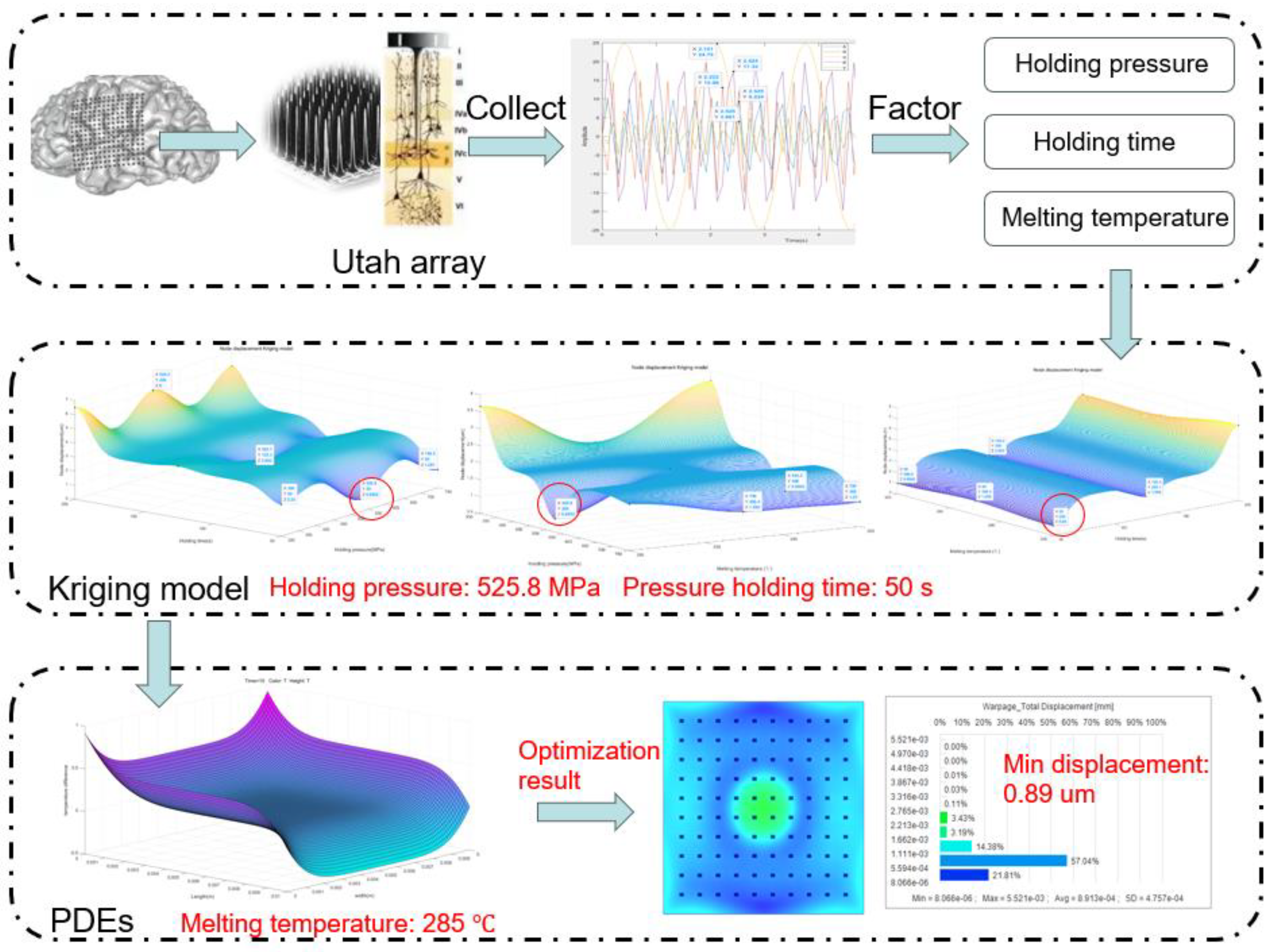
As shown in
Figure 2, it is the overall framework diagram of the optimized brain–computer interface in this paper. The injection molding method of in-mold electronic decoration is an advanced technique to embed the electronics directly into the brain tissue to provide more stable and accurate signal acquisition, thus overcoming the instability and interference problems of traditional external electrodes and providing a more accurate input source for the BCI system. Utah arrays, as electrode arrays for brain–computer interfaces, have excellent spatial resolution and signal capture capability, and can record the activities of a large number of neurons simultaneously, thus realizing a more comprehensive understanding of brain activities and providing more diverse and accurate input signals for brain–computer interface systems.
The Kriging prediction model is combined with PDEs to optimize the injection parameters of the brain–computer interface to further improve the performance of the brain–computer interface system. The PDEs model models and simulates the physical processes of the brain–computer interface and helps to select the optimal injection parameters for optimal electrode positions and layouts. The PDEs approach takes into account the effect of the injection parameters on the node displacements of the brain–computer interface, which allows for a more accurate description of the physical phenomena. The effect of injection molding parameters on brain–computer interface node displacements is investigated. The Kriging prediction model, as a powerful statistical tool, can accurately estimate the effect of injection molding parameters on performance based on the spatial distribution of available data points. Finally, the brain–computer interface node displacements before and after optimization are analyzed by combining Kriging and PDEs to verify their effects on signal transmission accuracy. This approach provides us with a comprehensive analytical tool to ensure that the performance of the BCI system is fully evaluated.
4. Case Study
In order to make brain–computer interfaces (BCIs) smaller and lighter for implantation, we have adopted in-mold electronics (IME) technology and injection molding using liquid silicone rubber (LSR) materials. The application of IME technology not only enables complex electronic components to be embedded directly into thin films, but also ensures the reliability and durability of the electronic components through a high-precision injection molding process. During the injection molding process, Utah arrays are precisely embedded into the flexible film, resulting in BCIs that are small in size, light in weight, and stable in performance.
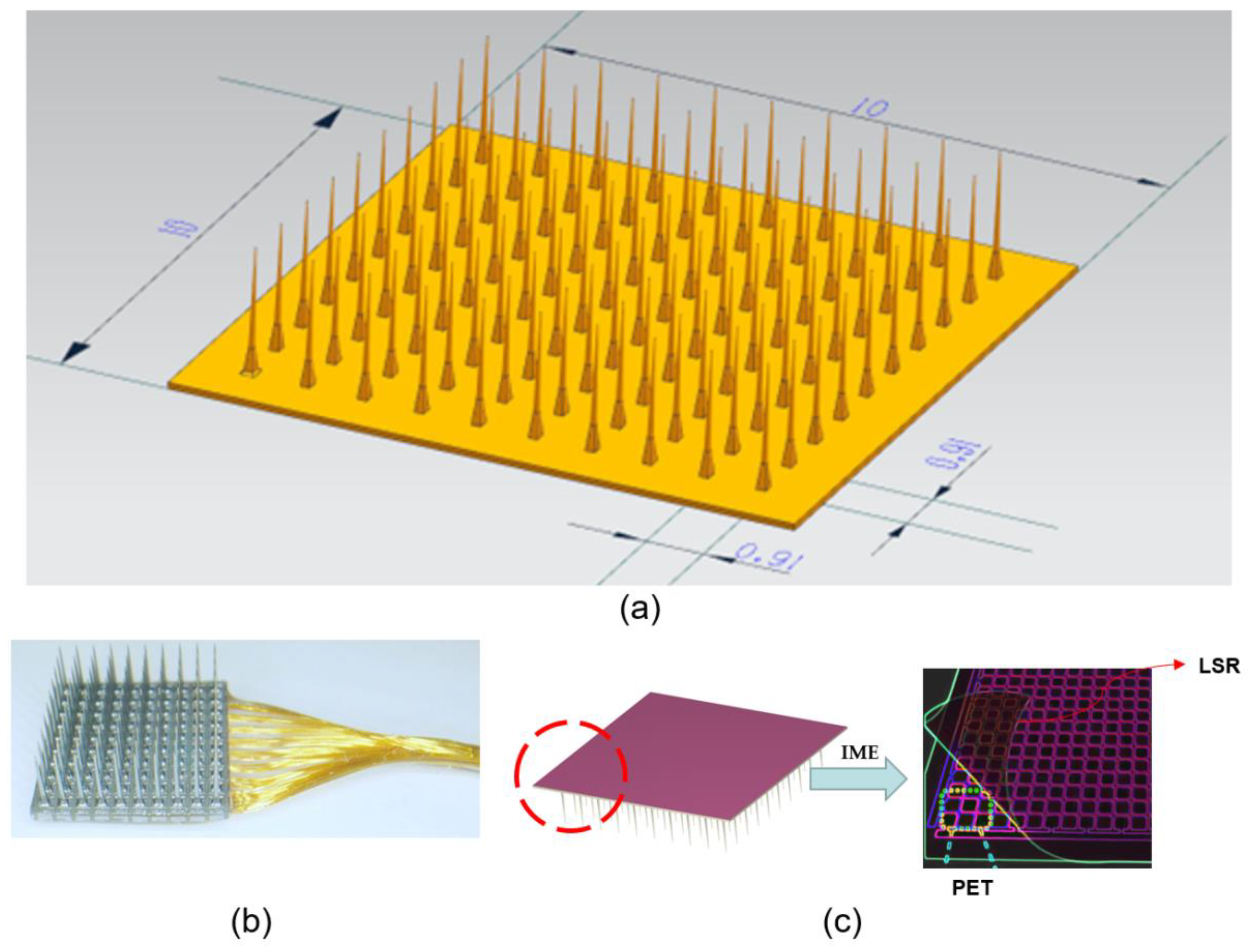
As shown in
Figure 5a, we designed the 3D model of the Utah array as a 10 × 10 mm square electrode plate with 100 tiny electrodes. For the Utah array, as shown in
Figure 5b, there is usually one connection line for each channel. This means that for 100 channels, there are typically 100 connection lines [
5]. These connecting lines are responsible for transmitting the signals from each channel to the appropriate multiplexer or demultiplexer and then to the external system.
When designing such a system, it is important to ensure that each connecting line transmits data independently without interfering or affecting the other lines. This may involve designing circuit boards, connectors, cables, or other equipment necessary to ensure that each connecting line can transmit data consistently. It is also necessary to ensure the reliability and stability of the entire system to avoid possible data loss or transmission errors.
Based on the literature research, this paper establishes 100 interface channels by running the Utah array of probes through the entire electrode plate [
10], providing wider coverage and higher acquisition accuracy for the signal acquisition and transmission of the brain–computer interface. The 100 channels were divided into two groups, yellow and green, with 50 channels in each group to reduce interference and cross-talk between signals and improve the accuracy and stability of signal transmission [
36]. In addition, after covering a layer of biocompatible LSR film, the array and connecting lines can be effectively protected from the external environment, improving the stability and durability of the system and extending the service life of the device. Therefore, the design method of
Figure 5c is chosen in this paper.
In Utah arrays, it is critical to ensure that the node displacements of the lines are not offset. Offsets in node displacement can lead to data inaccuracies, instability between array elements, and an increased risk of surgery. Maintaining the stability of the nodes of the Utah array line is critical to ensure its performance and reliability. We focus on optimizing node displacement by optimizing injection parameters.[
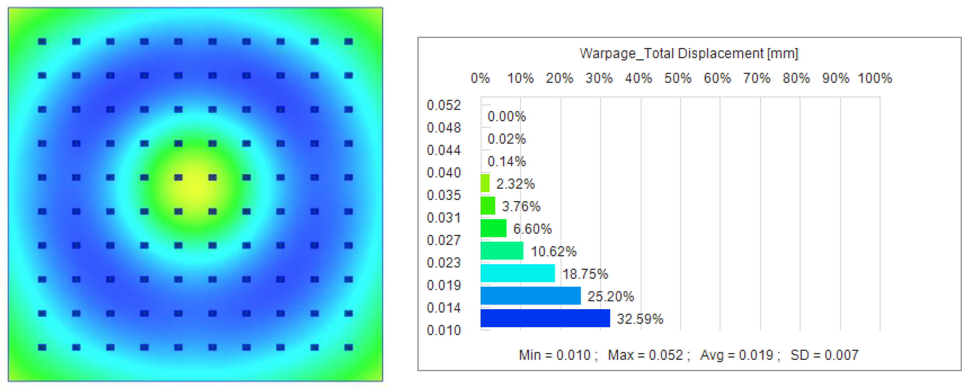
37]. Melt temperature affects the fluidity and melt state of the plastic, injection speed affects the filling of the plastic in the mold cavity, and holding time and holding pressure determine the shrinkage and stability of the plastic during the cooling and curing stages. We used the initial data for the experimental study with a holding pressure of 750 MPa, a holding time of 175 s, and a melting temperature of 285 °C for the simulation in Moldex3D version 2023 software, and obtained the results shown in
Figure 6. The maximum node displacement is 0.052 mm, the minimum is 0.010 mm, and the average node displacement is 0.19 mm, a value that may have a serious negative impact on the brain–computer interface’s functionality.
To further improve the performance and stability of the brain–computer interface, we need to optimize the injection parameters. This will involve more experimentation and data collection to determine the optimal combination of injection molding parameters that significantly reduces node displacement and improves the stability and performance of the interface. By optimizing key parameters such as holding pressure, holding time, melting temperature, etc., we hope to reduce the node displacement to a negligible level, thus enhancing the overall functionality of the brain–computer interface.
In this paper, we propose an injection molding parameter optimization method by combining the Kriging prediction model with partial differential equations (PDEs.) Kriging is a statistically based method that can provide a reliable basis for parameter optimization in the injection molding process by analyzing and predicting known data points. Partial differential equations are used to describe the complex physical phenomena of material flow, heat transfer and curing during the injection molding process. By combining these two methods, we can more comprehensively understand and control the effects of injection molding parameters on the molding process.
We first use the Kriging prediction model to perform a preliminary optimization of key parameters such as holding pressure, holding time and melt temperature during the injection molding process. Based on the prediction results of this model, the optimized parameter values were substituted into partial differential equations for simulation to evaluate the effects of different parameter combinations on nodal displacement. The simulation was carried out using Moldex3D version 2023 software. Through several iterations of optimization and simulation, we finally determined the optimal combination of injection parameters to significantly reduce node displacement and improve the stability and performance of the brain–computer interface.
5. Results and Discussion
In conducting the Kriging model analysis, we first adopted the orthogonal experimental design method to ensure the comprehensiveness and efficiency of the experimental design. Specifically, the holding pressure was set at 300–750 MPa, the holding time was set at 50–200 s, and the melting temperature was set at 285–300 °C. In order to simulate the effects of different parameter combinations on the nodal displacements, we performed simulations in Moldex3D.
In the orthogonal experimental design, we chose three levels of holding pressure, holding time and melting temperature, corresponding to low, medium and high values within the set range. Twenty sets of data were selected, as shown in
Table 1. The displacements here were obtained by simulating different combinations of parameters and by setting the nodes in the simulation software. These data provide a solid foundation for the subsequent Kriging prediction model.
We set up several key nodes in the simulation model, which are located on the lines in the film designed to receive EEG signals. During the simulation process, the software will record the position change in each node to obtain the node displacement. Through multiple simulations and parameter adjustments, we can obtain the node displacement data under different combinations of injection molding parameters.
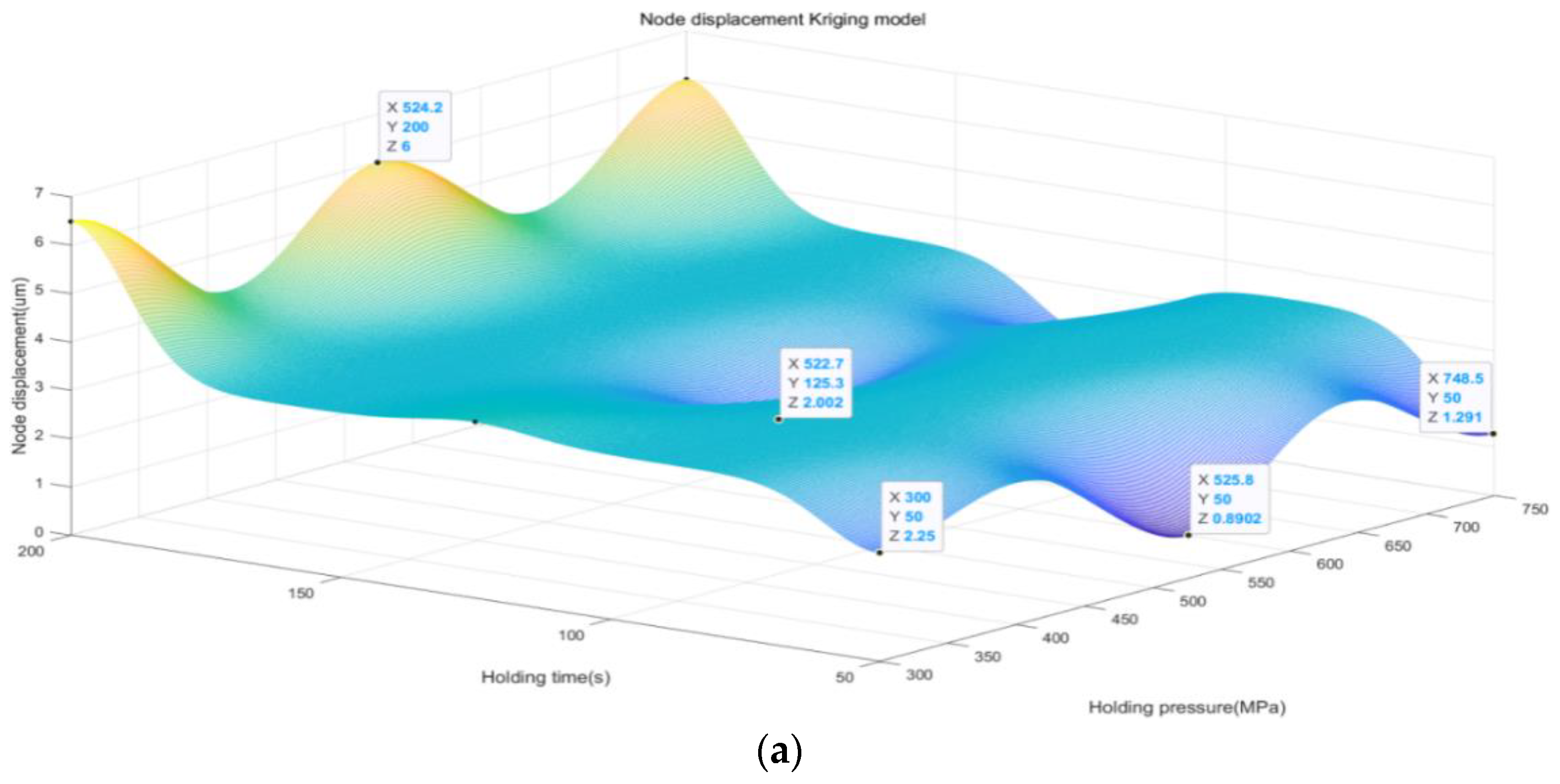
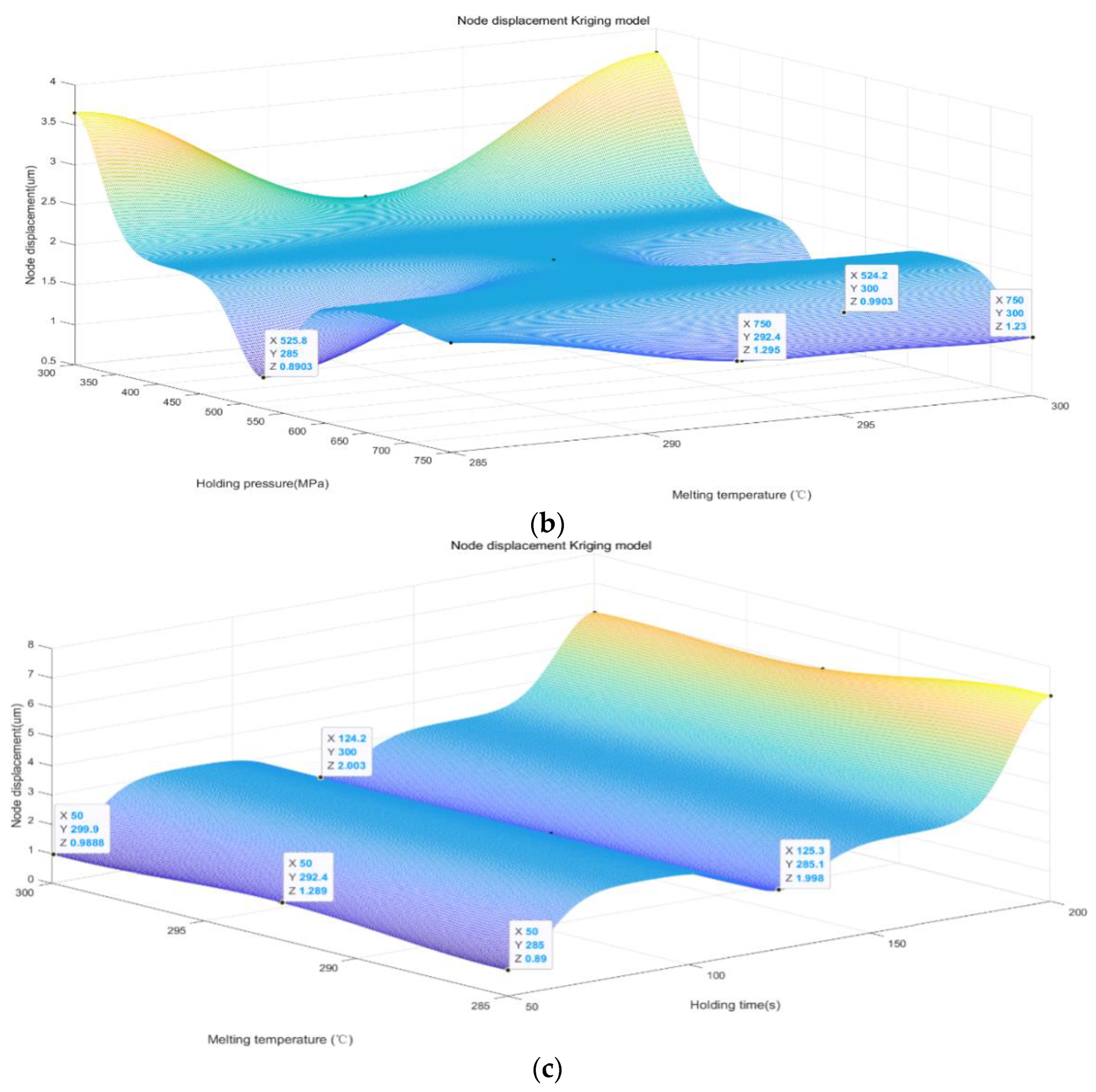
The Kriging model generates a predictive model of node displacement by interpolating known data points. Based on this model, we can predict the node displacements under different combinations of injection molding parameters, thus identifying the optimal possible parameter combinations. Therefore, with the above 20 sets of data, we use the Kriging model to analyze and predict the simulation data and obtain the result graph, as shown in
Figure 7.
First, we observed that an increase in the holding pressure in the range of 300–750 MPa had a significant effect on the node displacement of the BCI. As the holding pressure increases, we observe a relative decrease in node displacement, which suggests that increasing the holding pressure within a certain range can effectively improve the stability and accuracy of the BCI. This result highlights the important influence of holding pressure on the performance of BCI and suggests that the optimization of holding pressure should be fully considered when designing BCI.
Second, the decrease in the holding pressure time in the range of 50–200 s also had a significant effect on the node displacement. We found that the node displacement relatively decreases with the decrease in holding pressure time, indicating that a shorter holding pressure time can help to reduce the displacement problem of the BCI and thus improve its stability and performance. This finding emphasizes the importance of precisely controlling the holding pressure time during the preparation of BCI to ensure that the BCIs can exhibit stable and reliable properties in practical applications.
Finally, although we note that the melting temperature in the range of 285–300 °C has less effect on the node displacement, it still affects the performance of the BCI to some extent. This suggests that the appropriate choice of melting temperature is still one of the crucial factors in the preparation process of BCI. The comprehensive consideration of the effects of holding pressure, holding time, and melting temperature on node displacement can further optimize the design of BCI and improve their stability and performance, so as to better meet the needs of practical applications.
Through our prediction model, we find that the minimum node displacement is only 0.89 µm, which indicates that we are able to achieve a very high level of node displacement control under a certain holding pressure, holding time, and melting temperature. Specifically, we found that the performance of the BCI was optimized at a holding pressure of 525 MPa, a holding time of 50 s, and a melt temperature of 285 °C.
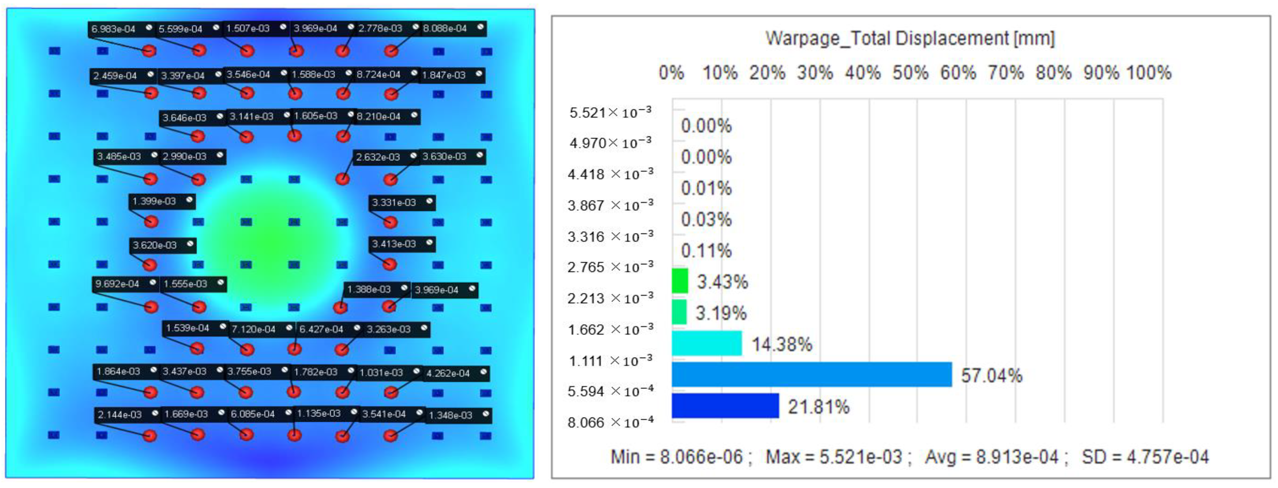
The resultant plots of node displacements are obtained by simulation analysis using the optimal parameter combinations obtained from the Kriging prediction model. As shown in
Figure 8, the maximum displacement was reduced from 0.019 mm to only 0.89 µm with an optimization rate of 95.32%. This shows that the Kriging method has a significant role in improving the nodal displacement.
In our observations of the optimized Utah array, we found that the probe node displacements at the positions shown in
Figure 8 ranged from 0.008 µm to 0.39 µm. Based on this observation, we decided that the signals obtained from the probes at these locations are usually selected for analysis during signal acquisition. This strategy is based on a thorough consideration of the distribution of node displacements and helps ensure that the signal data we obtain is more accurate and reliable. By focusing on these four locations, we are able to capture the neural signal information transmitted by the BCI more accurately and avoid the interference caused by the displacement of probes in other regions on the signal acquisition and analysis process.
Specifically, melt temperature plays a critical role in the injection molding process, directly affecting material flow, filling properties, and the mechanical and electrical characteristics of the final product. Within the constraints of the material selected, even small temperature variations may significantly affect nodal displacement and product quality, although the range of melt temperatures is small. Therefore, with PDEs analysis, it is possible to accurately simulate the behavior of the material at different melting temperatures and find the temperature value that is most conducive to reducing nodal displacement. In the PDEs analysis, we constructed a mathematical model describing the heat transfer and material flow during the injection molding process. The model takes into account the effect of melt temperature on material viscosity, thermal conductivity and density, which enables us to simulate the material filling and curing process at different temperatures.
In the analysis of PDEs, we focused on the variation of the melting temperature in the range of 285–300 °C. The results are summarized in the following sections. First, we constructed a mathematical model which takes into account the effect of the melting temperature on the viscosity, thermal conductivity and density of the material. By setting different melt temperatures, we simulated the flow and solidification process of the material in the mold.
In this study, in order to further optimize the nodal displacements, we first focused on the variation of the melting temperature in the range of 285–300 °C by Kriging analysis, and came up with the optimal value of 285 °C for the melting temperature. Based on this result, we performed a detailed analysis of the melting temperature of 285 °C using the partial differential equations (PDEs) method.
Through the simulation and analysis of the PDEs method, we obtained the three-dimensional temperature distribution graph shown in
Figure 9 in MATLAB. This figure shows the temperature distribution of the material in the mold at the melting temperature of 285 °C.
Figure 9 shows that the temperature difference is small and the overall temperature change is relatively smooth. The small temperature gradient means that the temperature changes at various points within the material are not significant, which helps to reduce the uneven material shrinkage due to temperature differences and further reduces the nodal displacement. The temperature distribution is more stable over a length and width range of 0.01 mm. This indicates that at this temperature, the flow and filling process of the material is more stable, and there is no obvious overheating or uneven cooling phenomenon.
Based on the above analysis, we confirm that a melt temperature of 285 °C provides optimal temperature conditions during the injection molding process. This temperature not only ensures good fluidity and the uniform temperature distribution of the material, but also effectively reduces nodal displacement and improves the stability and performance of the brain–computer interface.
Combining the Kriging prediction model and partial differential equations (PDEs) method, we optimized the key parameters in the injection molding process and finally determined the optimal combination of injection molding parameters: a holding pressure of 525 MPa, a holding time of 50 s, a melting temperature of 285 °C, and a nodal displacement of 0.89 µm. This combination greatly reduced nodal displacement and improved stability and performance.
From the results, the melting temperature of 285 °C ensured uniform flow and the stable filling of the material, which was essential to reduce the nodal displacement caused by the temperature difference. The smoothness of the temperature distribution reduces the shrinkage inhomogeneity of the material, which is essential to maintain the precise position of the electronic components in the Utah array, thus improving the accuracy and reliability of signal transmission.
The combination of the Kriging model and PDEs methodology provides an effective tool for injection molding parameter optimization. The Kriging model provides a theoretical basis for parameter optimization by analyzing and predicting known data points, while the PDEs method describes in detail the physical behavior of the material during the injection molding process, such as flow and cure. The combination of the two allows us to accurately assess the effects of different parameter combinations on nodal displacement in simulations, and thus find the optimal injection molding conditions.
The research in this paper was conducted based on simulation models and no actual objects were developed. All optimization results and conclusions are theoretical, and future work will include the fabrication of actual samples and experimental validation to further verify the effectiveness of the simulation results for practical applications. Although these methods performed well in our study, their adaptability and generalization ability under different materials and process conditions still need to be further verified. In actual production, various uncertainties and process variations may be encountered, which may affect the accuracy of model predictions. Therefore, the model needs to be further validated and adapted in the future to meet the challenges in actual production.
Errors may exist between experimental and simulated data, and thus these errors need to be analyzed and corrected to ensure the accuracy and reliability of the model. Through an in-depth analysis of the consistency problems of experimental and simulated data, as well as the technical bottlenecks in practical applications, we can more clearly recognize the limitations of the existing methods and take improvement measures in future research to further enhance the optimization effect and application value of the injection molding process.
