
Structure and Deformation Behavior of Polyphenylene Sulfide-Based Laminates Reinforced with Carbon Fiber Tapes Activated by Cold Atmospheric Plasma


Abstract
:1. Introduction
2. Materials and Methods
2.1. Experimental Studies
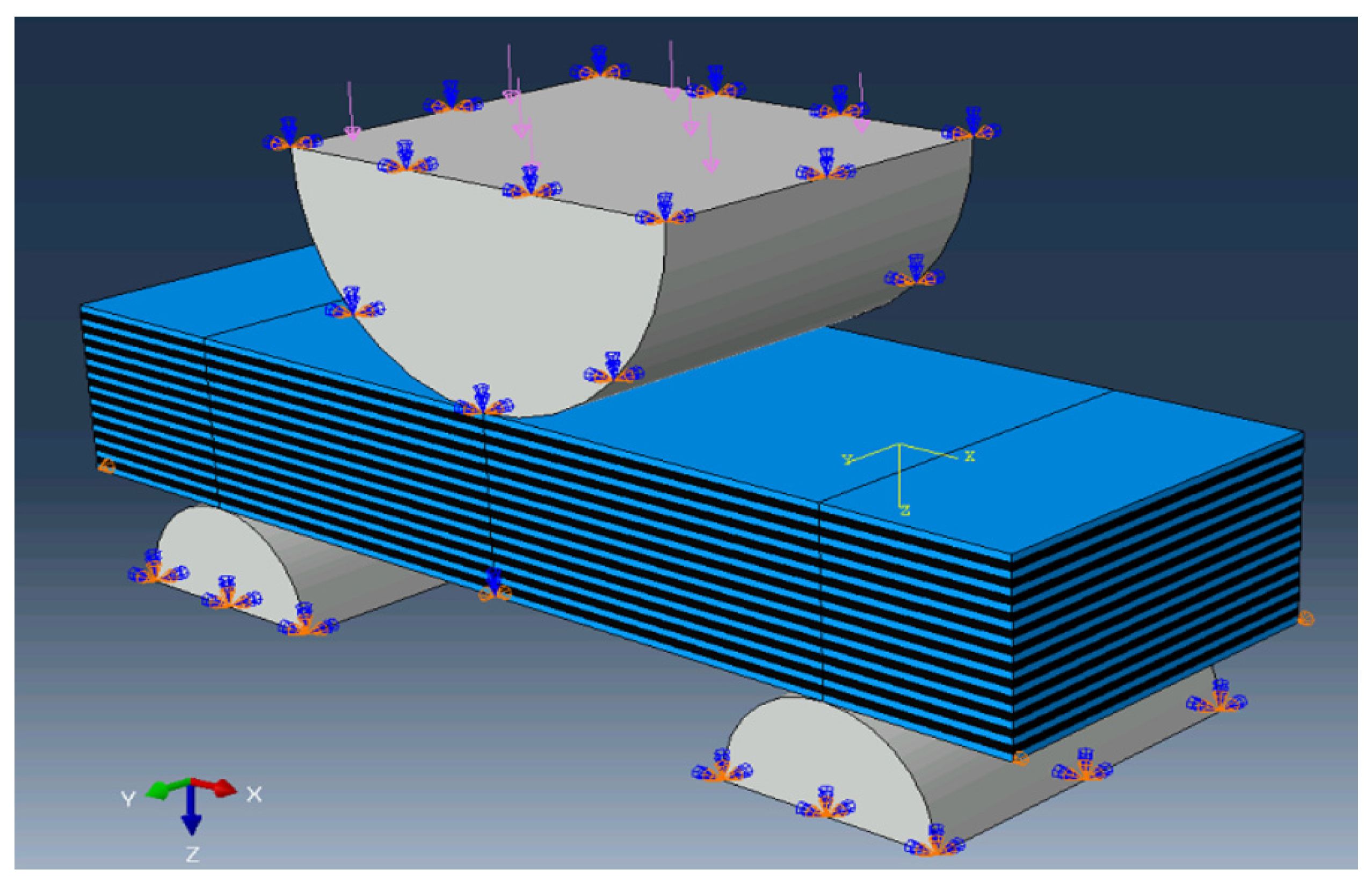
2.2. The Computer Simulation Technique
- The supports were rigidly fixed;
- A load was applied to the upper roller along the Oz axis direction, but its displacement was prohibited along the other ones.
3. Results
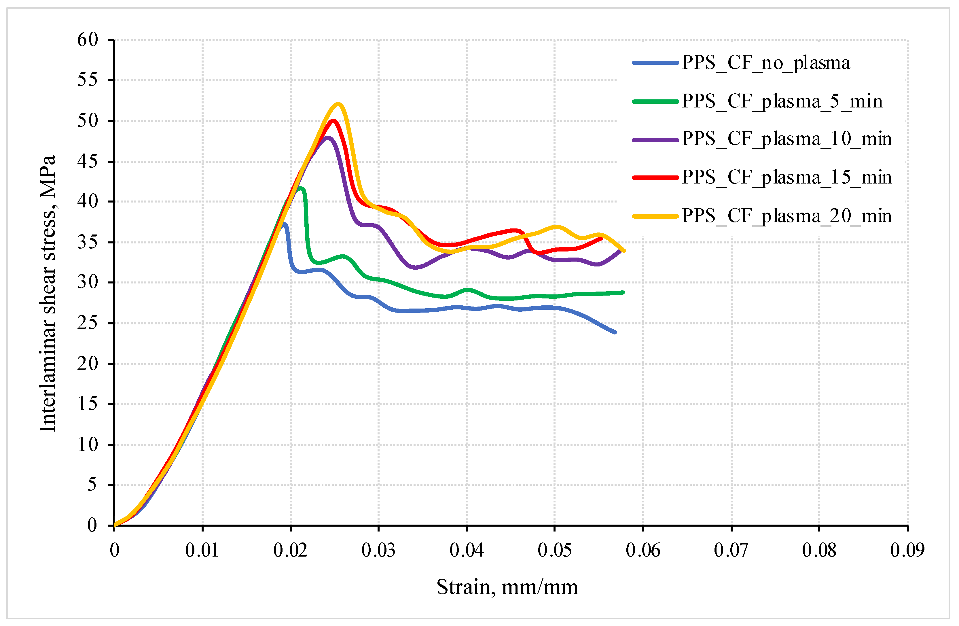
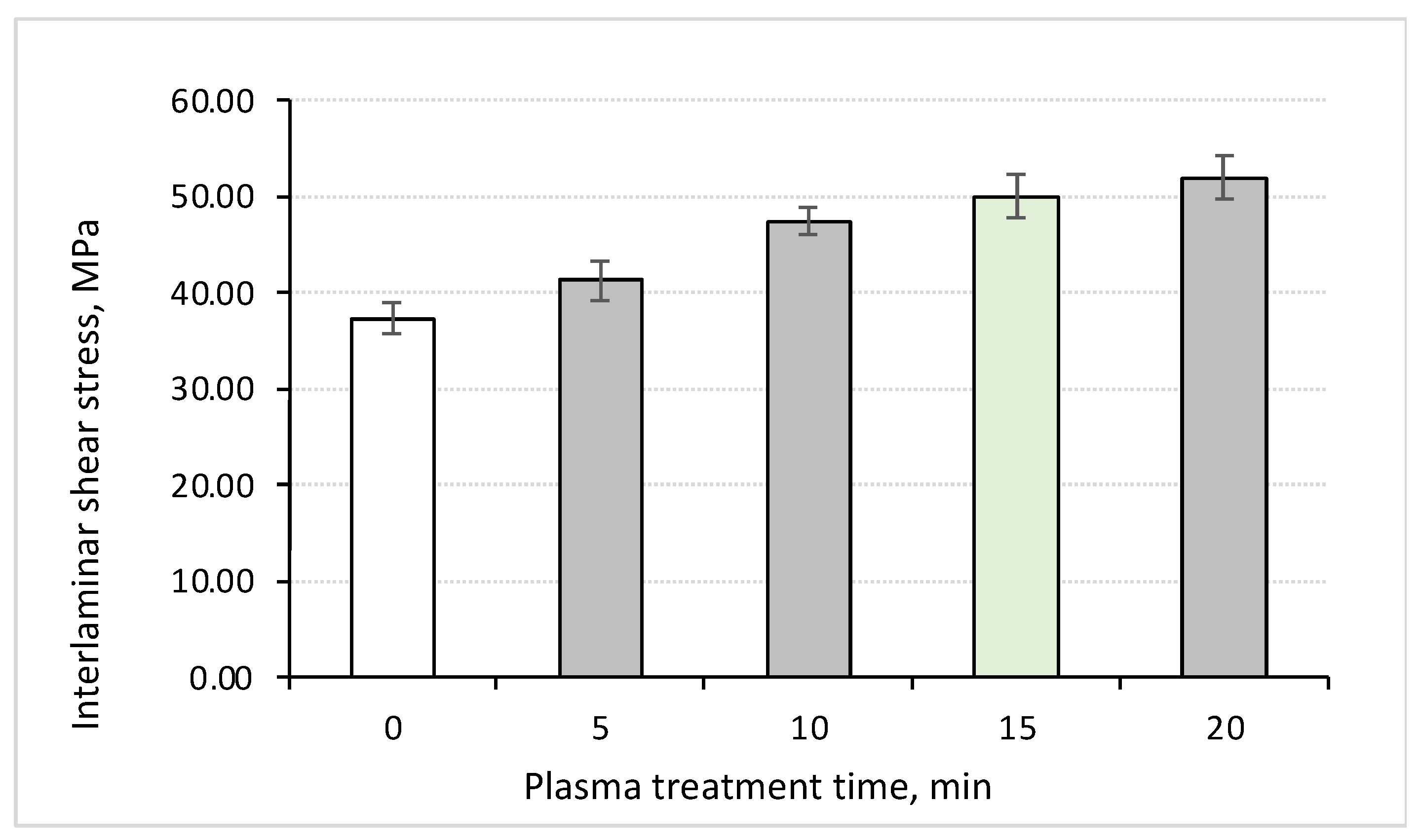
3.1. The ILSS Test
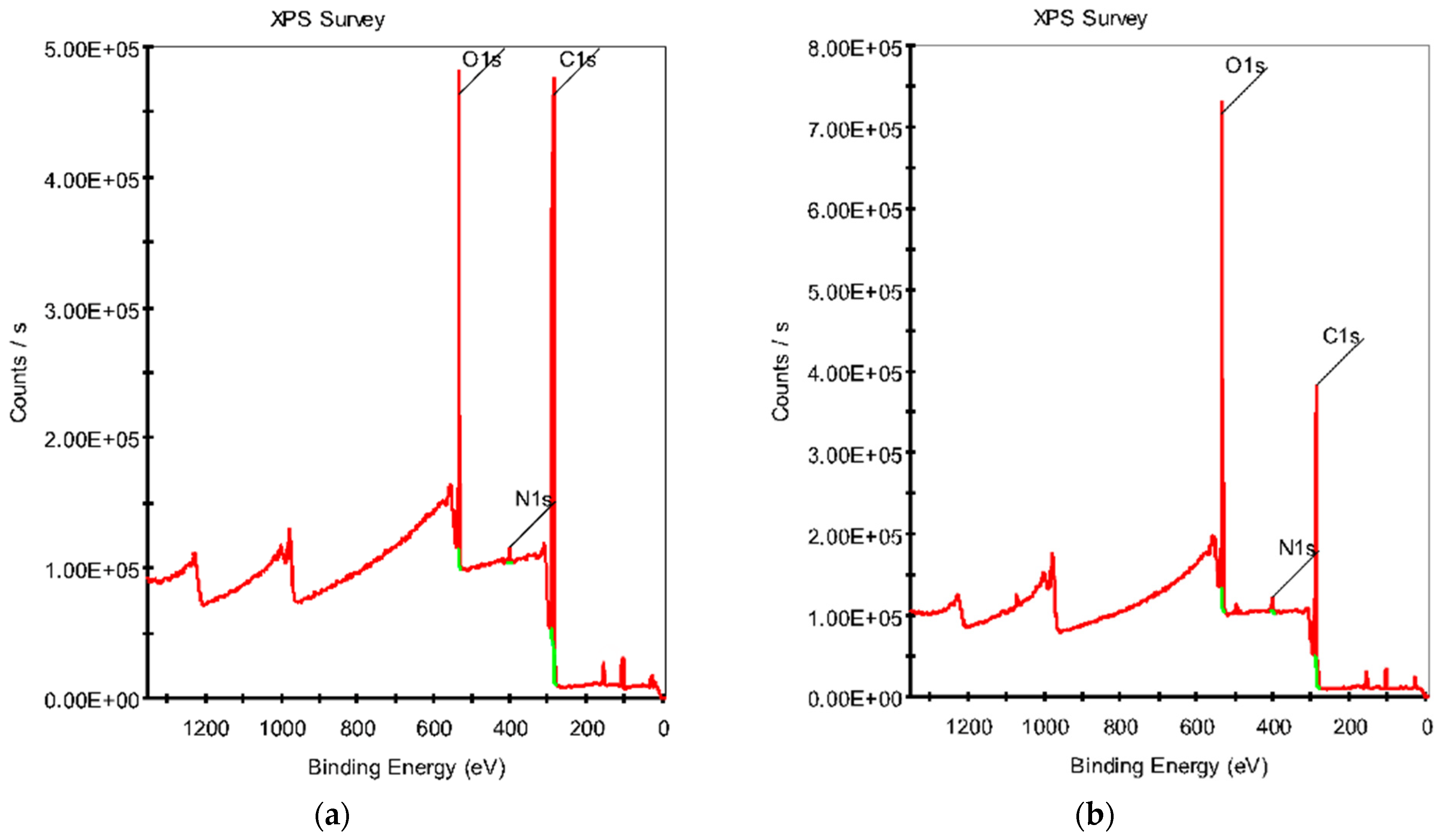
3.2. XPS Analysis
3.3. The Structural Studies
3.4. Computer Simulation
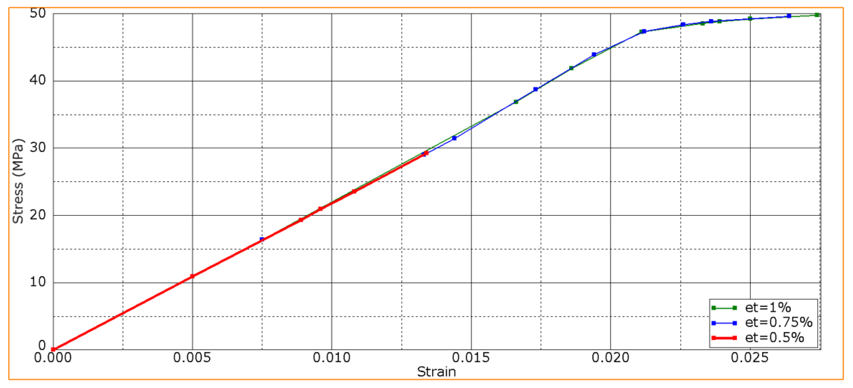
- At the minimum ετ value of 0.5%, a crack formed in the CF-containing layers at a εb bending strain of ~0.8% (Figure 11), and then, the remaining layers fractured under the loading member without delamination.
- When the shear strain level increased up to 0.75%, the crack in the CF-containing layers initiated later. However, this fact generally did not affect the slope of the curve. Then, delamination initiated, causing sample failure through the progress of delamination (as shown in Figure 7, Figure 8 and Figure 9).
- At shear strain levels of ≥1%, cracks did not form in the CF-containing layers. Initially, delamination initiated, and then, the PPS matrix cracked. Sample failure proceeded through the delamination mechanism.
4. Discussion
5. Conclusions
- The plasma treatment of CFs was shown to be an effective way to activate their surface and subsequently increase their ILSS values. It was demonstrated that an acceptable ILSS level was achieved after a DRE plasma treatment duration of 15 min, whereas the effect increased slightly with a subsequent increase in duration.
- As a result of the cold plasma treatment of CFs, their surface roughness increased and functional groups were grafted. This fact was confirmed by the XPS data, which showed a change in the chemical composition and the formation of reactive oxygen-containing groups. In turn, they made it possible to increase the adhesive bond between the polymer binder and reinforcing fibers. The SEM observation of the PPS/CF laminates clearly demonstrated a difference in adhesive interaction at the PPS/CF interface. After the DRE plasma treatment, CFs were better wetted with the polymer, and the samples cohesively fractured predominantly through the matrix, but not along the PPS/CF interface, as was observed for the sample reinforced with the untreated CFs.
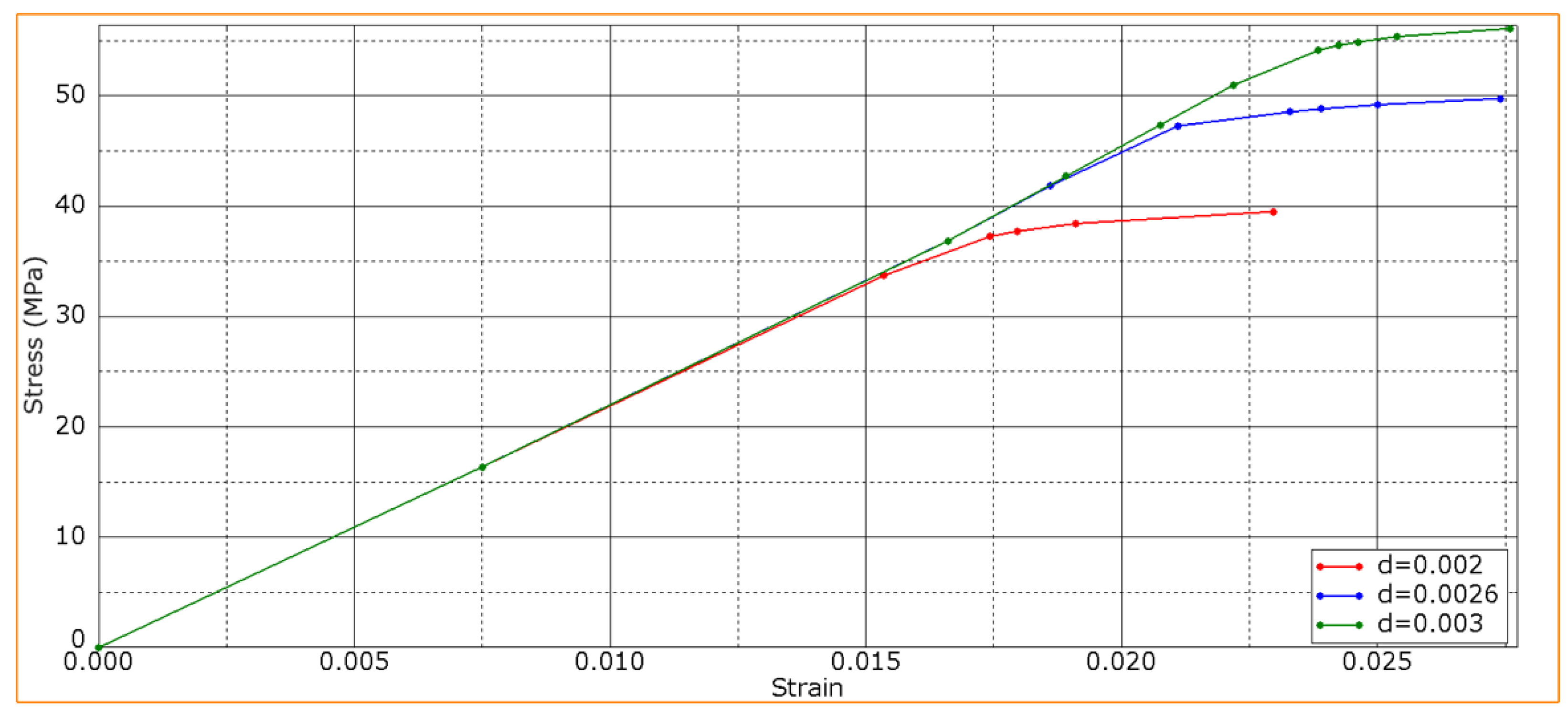
- The computer simulation results showed that raising the adhesive strength enhanced the ILSS values but reduced resistance to transverse cracking under the loading member. In general, higher flexural strength of the PPS/CF laminates was achieved with a greater interlayer adhesion level, which was consistent with the obtained experimental data.
- The related effects of the DRE cold plasma treatment of CFs included damage to their surface and a reduction in their tensile strength. However, this fact did not affect their flexural strength under the three-point bending conditions, since CFs were fractured at the interlayer boundary earlier. Reducing the shear strain of the CF-containing layers in the normal direction (along the fibers) did not lead to its decrease for the PPS/CF laminates as a whole in three-point bending. Nevertheless, at shear strain values of <0.5%, the sample fractured through the CF-containing layers. At low shear strain of the CF-containing layers, changing the adhesion level did not affect the strength, which remained constant at the level of 29 MPa. Raising the shear strain of the CF-containing layers above 0.75% influenced the fracture process, but the strength of the PPS/CF laminates did not vary generally.
Author Contributions
Funding
Institutional Review Board Statement
Informed Consent Statement
Data Availability Statement
Acknowledgments
Conflicts of Interest
References
- Vieille, B.; Aucher, J.; Taleb, L. Carbon Fiber Fabric Reinforced PPS Laminates: Influence of Temperature on Mechanical Properties and Behavior. Adv. Polym. Technol. 2011, 30, 80–95. [Google Scholar] [CrossRef]
- Shi, H.; Villegas, I.F.; Bersee, H.E.N. Strength and Failure Modes in Resistance Welded Thermoplastic Composite Joints: Effect of Fibre–Matrix Adhesion and Fibre Orientation. Compos. Part A Appl. Sci. Manuf. 2013, 55, 1–10. [Google Scholar] [CrossRef]
- Sumesh, K.R.; Anton, J.; Spatenka, P.; Sourkova, H.J. Experimental Studies on the Influence of Plasma Treatment of Polyethylene in Carbon Fiber Composites: Mechanical and Morphological Studies. Polymers 2022, 14, 1095. [Google Scholar] [CrossRef]
- Buketov, A.V.; Sapronov, O.O.; Brailo, M.V.; Maruschak, P.O.; Yakushchenko, S.V.; Panin, S.V.; Nigalatiy, V.D. Dynamics of Destruction of Epoxy Composites Filled with Ultra-Dispersed Diamond under Impact Conditions. Mech. Adv. Mat. Struct. 2018, 27, 725–733. [Google Scholar] [CrossRef]
- Wypych, G. PPS Poly(p-Phenylene Sulfide). In Handbook of Polymers; Elsevier: Amsterdam, The Netherlands, 2012; pp. 511–515. [Google Scholar] [CrossRef]
- Zuo, P.; Tcharkhtchi, A.; Shirinbayan, M.; Fitoussi, J.; Bakir, F. Overall Investigation of Poly (Phenylene Sulfide) from Synthesis and Process to Applications—A Review. Macromol. Mater. Eng. 2019, 304, 1800686. [Google Scholar] [CrossRef]
- Be Begum, S.A.; Rane, A.V.; Kanny, K. Applications of Compatibilized Polymer Blends in Automobile Industry. In Compatibilization of Polymer Blends; Elsevier: Amsterdam, The Netherlands, 2020; pp. 563–593. [Google Scholar] [CrossRef]
- Garmabi, M.M.; Shahi, P.; Tjong, J.; Sain, M. 3D Printing of Polyphenylene Sulfide for Functional Lightweight Automotive Component Manufacturing through Enhancing Interlayer Bonding. Add. Manuf. 2022, 56, 102780. [Google Scholar] [CrossRef]
- Yu, Y.; Xiong, S.; Huang, H.; Zhao, L.; Nie, K.; Chen, S.; Xu, J.; Yin, X.; Wang, H.; Wang, L. Fabrication and Application of Poly (Phenylene Sulfide) Ultrafine Fiber. React. Funct. Polym. 2020, 150, 104539. [Google Scholar] [CrossRef]
- de Leon, A.C.; Chen, Q.; Palaganas, N.B.; Palaganas, J.O.; Manapat, J.; Advincula, R.C. High Performance Polymer Nanocomposites for Additive Manufacturing Applications. React. Funct. Polym. 2016, 103, 141–155. [Google Scholar] [CrossRef]
- Chen, G.; Mohanty, A.K.; Misra, M. Progress in Research and Applications of Polyphenylene Sulfide Blends and Composites with Carbons. Compos. Part B Eng. 2021, 209, 108553. [Google Scholar] [CrossRef]
- Montagna, L.S.; Kondo, M.Y.; Callisaya, E.S.; Mello, C.; Souza, B.R.D.; Lemes, A.P.; Botelho, E.C.; Costa, M.L.; Alves, M.C.D.S.; Ribeiro, M.V.; et al. A Review on Research, Application, Processing, and Recycling of PPS Based Materials. Polímeros 2022, 32, e2022005. [Google Scholar] [CrossRef]
- Montagna, L.S.; Morgado, G.F.d.M.; Marini, J.; Guimarães, A.; Passador, F.R.; Rezende, M.C. Mechanical Properties of Carbon Fiber/PPS Laminates Processed by Hot Compression Molding under Different Consolidation Cycles. Polym. Compos. 2023, 44, 3358–3371. [Google Scholar] [CrossRef]
- Oshima, S.; Higuchi, R.; Kato, M.; Minakuchi, S.; Yokozeki, T.; Aoki, T. Cooling Rate-Dependent Mechanical Properties of Polyphenylene Sulfide (PPS) and Carbon Fiber Reinforced PPS (CF/PPS). Compos. Part A Appl. Sci. Manuf. 2023, 164, 107250. [Google Scholar] [CrossRef]
- Vinodhini, J.; Sudheendra, K.; Balachandran, M.; Bhowmik, S. Influence of Argon Plasma Treatment on Carbon Fibre Reinforced High Performance Thermoplastic Composite. High Perf. Polym. 2021, 33, 285–294. [Google Scholar] [CrossRef]
- Quan, D.; Bologna, F.; Scarselli, G.; Ivankovic, A.; Murphy, N. Interlaminar Fracture Toughness of Aerospace-Grade Carbon Fibre Reinforced Plastics Interleaved with Thermoplastic Veils. Compos. Part A Appl. Sci. Manuf. 2020, 128, 105642. [Google Scholar] [CrossRef]
- Ramirez, V.A.; Hogg, P.J.; Sampson, W.W. The Influence of the Nonwoven Veil Architectures on Interlaminar Fracture Toughness of Interleaved Composites. Compos. Sci. Technol. 2015, 110, 103–110. [Google Scholar] [CrossRef]
- Shin, Y.-C.; Kim, S.-M. Enhancement of the Interlaminar Fracture Toughness of a Carbon-Fiber-Reinforced Polymer Using Interleaved Carbon Nanotube Buckypaper. Appl. Sci. 2021, 11, 6821. [Google Scholar] [CrossRef]
- Khan, S.U.; Kim, J.-K. Improved Interlaminar Shear Properties of Multiscale Carbon Fiber Composites with Bucky Paper Interleaves Made from Carbon Nanofibers. Carbon 2012, 50, 5265–5277. [Google Scholar] [CrossRef]
- Rojas, J.A.; Santos, L.F.P.; Costa, M.L.; Ribeiro, B.; Botelho, E.C. Moisture and Temperature Influence on Mechanical Behavior of PPS/Buckypapers Carbon Fiber Laminates. Mat. Res. Expr. 2017, 4, 075302. [Google Scholar] [CrossRef]
- Wu, Z.; Pittman, C.U., Jr.; Gardner, S.D. Nitric Acid Oxidation of Carbon Fibers and the Effects of Subsequent Treatment in Refluxing Aqueous NaOH. Carbon 1995, 33, 597–605. [Google Scholar] [CrossRef]
- Mei, T.; Gao, M.; Wang, Y.; Huang, Y.; Chu, P.K. Effects of Acid Treatment and Plasma Micromachining on the Surface Properties of Carbon Fibers. Appl. Surf. Sci. 2022, 592, 153261. [Google Scholar] [CrossRef]
- Zhang, G.; Sun, S.; Yang, D.; Dodelet, J.-P.; Sacher, E. The Surface Analytical Characterization of Carbon Fibers Functionalized by H2SO4/HNO3 Treatment. Carbon 2008, 46, 196–205. [Google Scholar] [CrossRef]
- Peng, Q.; Li, Y.; He, X.; Lv, H.; Hu, P.; Shang, Y.; Wang, C.; Wang, R.; Sritharan, T.; Du, S. Interfacial Enhancement of Carbon Fiber Composites by Poly(Amido Amine) Functionalization. Compos. Sci. Technol. 2013, 74, 37–42. [Google Scholar] [CrossRef]
- Fan, R.; Yan, T.; Su, J.; Zhao, H.; Zha, L.; Zhou, J.; Zhu, S. A Water-Soluble PAAs Sizing Agent for Enhancing Interfacial Adhesion of Carbon Fiber Reinforced Polyphenylene Sulfide Composites (CF/PPS). J. Macromol. Sci. Part A 2022, 60, 29–37. [Google Scholar] [CrossRef]
- Chukov, D.; Nematulloev, S.; Torokhov, V.; Stepashkin, A.; Sherif, G.; Tcherdyntsev, V. Effect of Carbon Fiber Surface Modification on Their Interfacial Interaction with Polysulfone. Res. Phys. 2019, 15, 102634. [Google Scholar] [CrossRef]
- Fukunaga, A.; Ueda, S.; Nagumo, M. Air-Oxidation and Anodization of Pitch-Based Carbon Fibers. Carbon 1999, 37, 1081–1085. [Google Scholar] [CrossRef]
- Li, J. Interfacial Studies on the Ozone and Air-Oxidation-Modified Carbon Fiber Reinforced PEEK Composites. Surf. Interface Anal. 2009, 41, 310–315. [Google Scholar] [CrossRef]
- Chukov, D.; Nematulloev, S.; Zadorozhnyy, M.; Tcherdyntsev, V.; Stepashkin, A.; Zherebtsov, D. Structure, Mechanical and Thermal Properties of Polyphenylene Sulfide and Polysulfone Impregnated Carbon Fiber Composites. Polymers 2019, 11, 684. [Google Scholar] [CrossRef]
- Dilsiz, N. Plasma Surface Modification of Carbon Fibers: A Review. J. Adhes. Sci. Technol. 2000, 14, 975–987. [Google Scholar] [CrossRef]
- Mengjin, W.; Lixia, J.; Suling, L.; Zhigang, Q.; Sainan, W.; Ruosi, Y. Interfacial Performance of High-Performance Fiber-Reinforced Composites Improved by Cold Plasma Treatment: A Review. Surf. Interfaces 2021, 24, 101077. [Google Scholar] [CrossRef]
- Huang, Y.; Yu, Q.; Li, M.; Sun, S.; Zhao, H.; Jin, S.; Fan, J.; Wang, J. An Overview of Low-temperature Plasma Surface Modification of Carbon Materials for Removal of Pollutants from Liquid and Gas Phases. Plasma Process. Polym. 2020, 18, 2000171. [Google Scholar] [CrossRef]
- Sun, X.; Bao, J.; Li, K.; Argyle, M.D.; Tan, G.; Adidharma, H.; Zhang, K.; Fan, M.; Ning, P. Advance in Using Plasma Technology for Modification or Fabrication of Carbon-Based Materials and Their Applications in Environmental, Material, and Energy Fields. Adv. Funct. Mater. 2020, 31, 2006287. [Google Scholar] [CrossRef]
- Karoly, Z.; Romanszki, L.; Weltz, G.; Mohai, M.; Moczo, J.; Klebert, S. Comparison of Dielectric Barrier Discharge and Radio-Frequency Plasma Processing of Carbon Fibers. Express Polym. Lett. 2021, 15, 1004–1017. [Google Scholar] [CrossRef]
- Tiwari, S.; Sharma, M.; Panier, S.; Mutel, B.; Mitschang, P.; Bijwe, J. Influence of Cold Remote Nitrogen Oxygen Plasma Treatment on Carbon Fabric and Its Composites with Specialty Polymers. J. Mat. Sci. 2010, 46, 964–974. [Google Scholar] [CrossRef]
- Sidorina, A.I.; Imametdinov, E.S. Modification of Surface of Carbon Fiber Materials by Plasma Treatment (Review). Fibre Chem. 2020, 52, 96–99. [Google Scholar] [CrossRef]
- Jialanella, G.L. Advances in Bonding Plastics. In Advances in Structural Adhesive Bonding; Elsevier Inc.: Amsterdam, The Netherlands, 2010; pp. 237–264. [Google Scholar] [CrossRef]
- Zheng, H.; Zhang, W.; Li, B.; Zhu, J.; Wang, C.; Song, G.; Wu, G.; Yang, X.; Huang, Y.; Ma, L. Recent Advances of Interphases in Carbon Fiber-Reinforced Polymer Composites: A Review. Compos. Part B Eng. 2022, 233, 109639. [Google Scholar] [CrossRef]
- Lin, J.; Sun, C.; Min, J.; Wan, H.; Wang, S. Effect of Atmospheric Pressure Plasma Treatment on Surface Physicochemical Properties of Carbon Fiber Reinforced Polymer and its Interfacial Bonding Strength with Adhesive. Compos. Part B Eng. 2020, 199, 108237. [Google Scholar] [CrossRef]
- Xiao, J.; Zhang, X.; Zhao, Z.; Liu, J.; Chen, Q.; Wang, X. Rapid and Continuous Atmospheric Plasma Surface Modification of PAN-Based Carbon Fibers. ACS Omega 2022, 7, 10963–10969. [Google Scholar] [CrossRef]
- Zhang, Z.; Wilson, J.L.; Kitt, B.R.; Flaherty, D.W. Effects of Oxygen Plasma Treatments on Surface Functional Groups and Shear Strength of Carbon Fiber Composites. ACS Appl. Polym. Mater. 2021, 3, 986–995. [Google Scholar] [CrossRef]
- Radjef, R.; Jarvis, K.L.; Fox, B.L.; McArthur, S.L. Comparing the Properties of Commercially Treated and Air Plasma Treated carbon fibers. Surf. Coat. Technol. 2021, 408, 126751. [Google Scholar] [CrossRef]
- Wen, L.; Xu, X.; Qin, L. Effect of Low-Temperature Plasma Surface Treatment on Bonding Properties of Single-Lap Joint of Thermosetting Composites. Polymers 2023, 15, 1631. [Google Scholar] [CrossRef]
- Yuan, L.Y.; Shyu, S.S.; Lai, J.Y. Plasma Surface Treatments of Carbon Fibers. Part 2: Interfacial Adhesion with Poly(Phenylene Sulfide). Compos. Sci. Technol. 1992, 45, 9–16. [Google Scholar] [CrossRef]
- Xu, D.; Liu, B.; Zhang, G.; Long, S.; Wang, X.; Yang, J. Effect of Air Plasma Treatment on Interfacial Shear Strength of Carbon Fiber–Reinforced Polyphenylene Sulfide. High Perf. Polym. 2015, 28, 411–424. [Google Scholar] [CrossRef]
- Santos, A.L.; Botelho, E.C.; Kostov, K.G.; Ueda, M.; da Silva, L.L.G. Carbon Fiber Surface Modification by Plasma Treatment for Interface Adhesion Improvements of Aerospace Composites. Adv. Mater. Res. 2016, 1135, 75–87. [Google Scholar] [CrossRef]
- Dong, Y.; Yu, T.; Wang, X.; Zhang, G.; Lu, J.; Zhang, M.; Long, S.; Yang, J. Improved Interfacial Shear Strength in Polyphenylene Sulfide/Carbon Fiber Composites via the Carboxylic Polyphenylene Sulfide Sizing Agent. Compos. Sci. Technol. 2020, 190, 108056. [Google Scholar] [CrossRef]
- Lee, H.; Kim, G.; Kim, K.; Kim, H.; Kim, D.U. Effect of Plasma Treatment Condition on Mechanical and Chemical Properties of Carbon Fibers. J. Mater. Eng. Perf. 2023, 32, 415–422. [Google Scholar] [CrossRef]
- Kosmachev, P.V.; Panin, S.V.; Panov, I.L.; Bochkareva, S.A. Surface Modification of Carbon Fibers by Low-Temperature Plasma with Runaway Electrons for Manufacturing PEEK-Based Laminates. Materials 2022, 15, 7625. [Google Scholar] [CrossRef]
- Lozhkomoev, A.S.; Glazkova, E.A.; Khorobraya, E.G.; Lerner, M.I.; Maltsev, A.N.; Podkovyrov, V.G. Modification of the Polymer Fiber Surface by DRE-plasma for Adhesion of Aluminum Oxyhydroxide Particles. Russ. Phys. J. 2013, 56, 384–388. [Google Scholar] [CrossRef]
- ASTM D2344/D2344M-22; Test Method for Short-Beam Strength of Polymer Matrix Composite Materials and Their Laminates. ASTM: West Conshohocken, PA, USA, 2022. [CrossRef]
- Panin, S.V.; Lyukshin, B.A.; Bochkareva, S.A.; Kornienko, L.A.; Nguyen, D.A.; Hiep, L.T.M.; Panov, I.L.; Grishaeva, N.Y. Material Design Methodology for Optimized Wear-Resistant Thermoplastic–Matrix Composites Based on Polyetheretherketone and Polyphenylene Sulfide. Materials 2020, 13, 524. [Google Scholar] [CrossRef]
- Kosmachev, P.V.; Alexenko, V.O.; Bochkareva, S.A.; Panin, S.V. Deformation Behavior and Fracture Patterns of Laminated PEEK- and PI-Based Composites with Various Carbon-Fiber Reinforcement. Polymers 2021, 13, 2268. [Google Scholar] [CrossRef]
- Vanin, G.A.; Wang, F.P. Konstruktsii Povyshennoy Plastichnosti (Reinforced Plastic Structures); Tekhnika: Kiyev, Ukraine, 1971. [Google Scholar]
- Gunyaev, G.M. Struktura i Svoistva Polimernykh Voloknistykh Kompozitov (Structure and Properties of Polymeric Fibrous Composites); Khimiya Publ.: Moscow, Russia, 1981. [Google Scholar]
- Altenbach, H.; Altenbach, J.; Kissing, W. Mechanics of Composite Structural Elements, 2nd ed.; Springer: Berlin/Heidelberg, Germany, 2018. [Google Scholar]
- Skudra, A.M.; Bulavs, F.Y. Prochnost Armirovannykh Plastikov (Strength of Reinforced Plastics); Khimiya Publ.: Moscow, Russia, 1982. [Google Scholar]
- ASTM D7264/D7264M-21; Test Method for Flexural Properties of Polymer Matrix Composite Materials. ASTM: West Conshohocken, PA, USA, 2021. [CrossRef]
- Albinmousa, J.; AlSadah, J.; Hawwa, M.A.; Al-Qahtani, H.M. Estimation of Mixed-Mode I/II Fracture of U-Notched Polycarbonate Specimens Using the TCD and SED Methods. Phys. Mesomech. 2023, 26, 66–81. [Google Scholar] [CrossRef]
- Balokhonov, R.R.; Romanova, V.A.; Buyakova, S.P.; Kulkov, A.S.; Bakeev, R.A.; Evtushenko, E.P.; Zemlyanov, A.V. Deformation and Fracture Behavior of Particle-Reinforced Metal Matrix Composites and Coatings. Phys. Mesomech. 2022, 25, 492–504. [Google Scholar] [CrossRef]
- Camanho, P.; Davila, C. Mixed-Mode Decohesion Finite Elements for the Simulation of Delamination in Composite Materials; Technical Report NASA/TM-2002-211737; NASA: Washington, DC, USA, 2002; pp. 1–42. [Google Scholar]
- Panin, V.E.; Egorushkin, V.E. Basic Physical Mesomechanics of Plastic Deformation and Fracture of Solids as Hierarchically Organized Nonlinear Systems. Phys. Mesomech. 2015, 18, 377–390. [Google Scholar] [CrossRef]
- Baghery Borooj, M.; Mousavi Shoushtari, A.; Nosratian Sabet, E.; Haji, A. Influence of Oxygen Plasma Treatment Parameters on the Properties of Carbon Fiber. J. Adh. Sci. Technol. 2016, 30, 2372–2382. [Google Scholar] [CrossRef]
- Lu, C.; Chen, P.; Yu, Q.; Ding, Z.; Lin, Z.; Li, W. Interfacial Adhesion of Plasma-Treated Carbon Fiber/Poly(Phthalazinone Ether Sulfone Ketone) Composite. J. Appl. Polym. Sci. 2007, 106, 1733–1741. [Google Scholar] [CrossRef]
- Luo, H.; Xiong, G.; Ren, K.; Raman, S.R.; Liu, Z.; Li, Q.; Ma, C.; Li, D.; Wan, Y. Air DBD plasma treatment on three-dimensional braided carbon fiber-reinforced PEEK composites for enhancement of in vitro bioactivity. Surf. Coat. Technol. 2014, 242, 1–7. [Google Scholar] [CrossRef]
- Kim, S.Y.; Baek, S.J.; Youn, J.R. New hybrid method for simultaneous improvement of tensile and impact properties of carbon fiber reinforced composites. Carbon 2011, 49, 5329–5338. [Google Scholar] [CrossRef]
- Park, S.-J.; Chang, Y.-H.; Moon, C.-W.; Suh, D.-H.; Im, S.-S.; Kim, Y.-C. A Study of Atmospheric Plasma Treatment on Surface Energetics of Carbon Fibers. Bull. Korean Chem. Soc. 2010, 31, 335–338. [Google Scholar] [CrossRef]
- Su, Y.; Liu, P.; Jing, D.; Zhang, X.; Zhang, S. Improved interfacial adhesion in carbon fiber/poly (ether ether ketone) composites with the sulfonated poly (ether ether ketone) sizing treatment. Appl. Polym. Sci. 2021, 138, 51326. [Google Scholar] [CrossRef]


| Plasma Treatment Duration | Ultimate Shear Strength τ, MPa | Relative Increase, % |
|---|---|---|
| Untreated | 37.3 ± 1.6 | – |
| tplasma = 5 min | 41.3 ± 2.1 | +11 |
| tplasma = 10 min | 47.4 ± 1.4 | +27 |
| tplasma = 15 min | 50.1 ± 2.2 | +35 |
| tplasma = 20 min | 52.0 ± 2.3 | +39 |
| CF Types | Elemental Compositions (%) | O/C | ||
|---|---|---|---|---|
| C1s | O1s | N1s | ||
| Untreated | 75.69 | 22.70 | 1.61 | 0.30 |
| After plasma treatment for 15 min | 65.50 | 33.25 | 2.03 | 0.51 |
| CF Types | Peak Assignment (%) | Total Oxygen-Containing Groups (%) | ||
|---|---|---|---|---|
| C–C | C–O | C=O | ||
| Untreated | 56.64 | 36.15 | 7.20 | 43.35 |
| After plasma treatment for 15 min | 45.70 | 34.87 | 19.43 | 54.30 |
| Interlayer Stiffness, K (MPa) | Average Flexural Modulus, E (MPa) |
|---|---|
| The experimental results | 2222 |
| 4200 | 2048 |
| 4500 | 2126 |
| 4900 | 2220 |
| The ετ Shear Strain in the CF-Containing Layers | Stage 1 (Crack Initiation in the CF-Containing Layers), εb | Stage 2 (Initiation of Delamination), εb | Stage 3 (the Beginning of Crack Propagation in the PPS Layers), εb |
|---|---|---|---|
| 0.50 | 0.0094 | – | – |
| 0.75 | 0.0140 | 0.021 | – |
| ≥1.00 | – | 0.021 | 0.026 |
| Composite | Plasma Type | Treatment Duration, min | Relative Enhancement of ILSS/IFSS after Plasma Treatment | Reference |
|---|---|---|---|---|
| Epoxy/CF | Oxygen RF plasma | 1 | ILSS +28% | Baghery Borooj et al. [63] |
| Epoxy/CF | Air dielectric barrier discharge (DBD) plasma | 1 | ILSS +23% | Xiao et al. [40] |
| PPESK/CF | Inductively coupled plasma (ICP) | 15 | ILSS +14% | Lu et al. [64] |
| PEEK/CF | Cold remote (N2 + O2) plasma (CRNOP) | 15 | ILSS +7% | Tiwari et al. [35] |
| PEEK/CF | Air DRE plasma | 15 | ILSS +54% | Kosmachev et al. [49] |
| PPS/CF | Ar, N2 and O2 RF plasma | 1–10 min | IFSS +150% | Yuan et al. [44] |
| PPS/CF | Air DBD plasma | – | IFSS +14% | Xu et al. [45] |
| PPS/CF | Air DBD plasma; glow discharge plasma | 3 15 | ILSS +23% ILSS +21% | Santos et al. [46] |
| PPS/CF | Air DRE plasma | 15 | ILSS +35% | [Current study] |
Disclaimer/Publisher’s Note: The statements, opinions and data contained in all publications are solely those of the individual author(s) and contributor(s) and not of MDPI and/or the editor(s). MDPI and/or the editor(s) disclaim responsibility for any injury to people or property resulting from any ideas, methods, instructions or products referred to in the content. |
© 2023 by the authors. Licensee MDPI, Basel, Switzerland. This article is an open access article distributed under the terms and conditions of the Creative Commons Attribution (CC BY) license (https://creativecommons.org/licenses/by/4.0/).
Share and Cite
Kosmachev, P.V.; Panin, S.V.; Panov, I.L.; Bochkareva, S.A. Structure and Deformation Behavior of Polyphenylene Sulfide-Based Laminates Reinforced with Carbon Fiber Tapes Activated by Cold Atmospheric Plasma. Polymers 2024, 16, 121. https://doi.org/10.3390/polym16010121
Kosmachev PV, Panin SV, Panov IL, Bochkareva SA. Structure and Deformation Behavior of Polyphenylene Sulfide-Based Laminates Reinforced with Carbon Fiber Tapes Activated by Cold Atmospheric Plasma. Polymers. 2024; 16(1):121. https://doi.org/10.3390/polym16010121
Chicago/Turabian StyleKosmachev, Pavel V., Sergey V. Panin, Iliya L. Panov, and Svetlana A. Bochkareva. 2024. "Structure and Deformation Behavior of Polyphenylene Sulfide-Based Laminates Reinforced with Carbon Fiber Tapes Activated by Cold Atmospheric Plasma" Polymers 16, no. 1: 121. https://doi.org/10.3390/polym16010121
APA StyleKosmachev, P. V., Panin, S. V., Panov, I. L., & Bochkareva, S. A. (2024). Structure and Deformation Behavior of Polyphenylene Sulfide-Based Laminates Reinforced with Carbon Fiber Tapes Activated by Cold Atmospheric Plasma. Polymers, 16(1), 121. https://doi.org/10.3390/polym16010121