
Recent Progress of the Preparation and Application of Electrospun Porous Nanofibers


Abstract
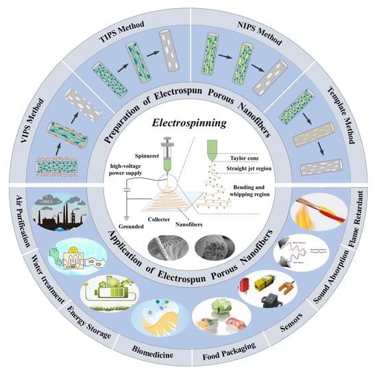
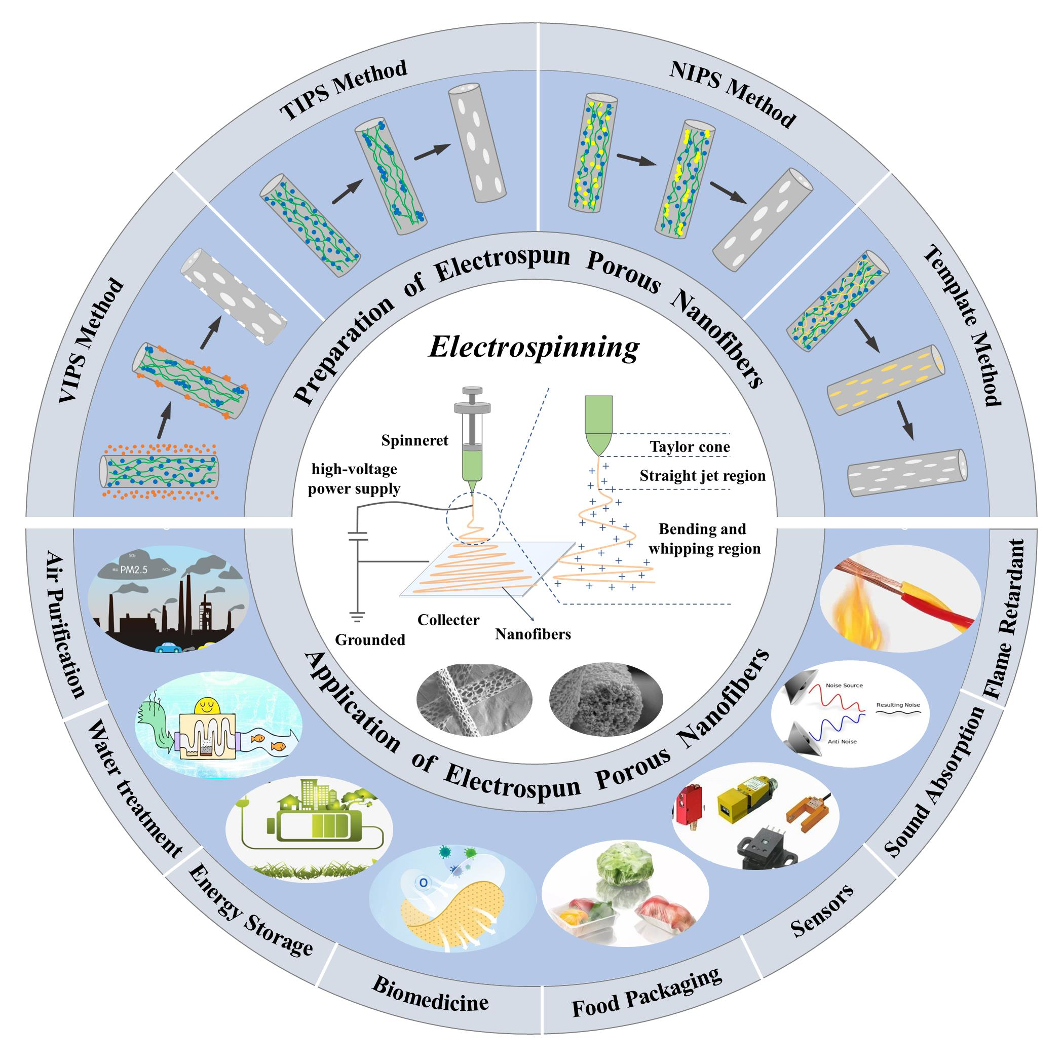
1. Introduction
2. Polymers in Electrospun Porous Fibers
3. Pore Formation in Electrospun Porous Fibers
3.1. Template Method
3.1.1. Using Polymers as Templates
3.1.2. Using Metals or Metal Oxides as Templates
3.1.3. Using Inorganic Salts as Templates
3.2. Phase Separation Method
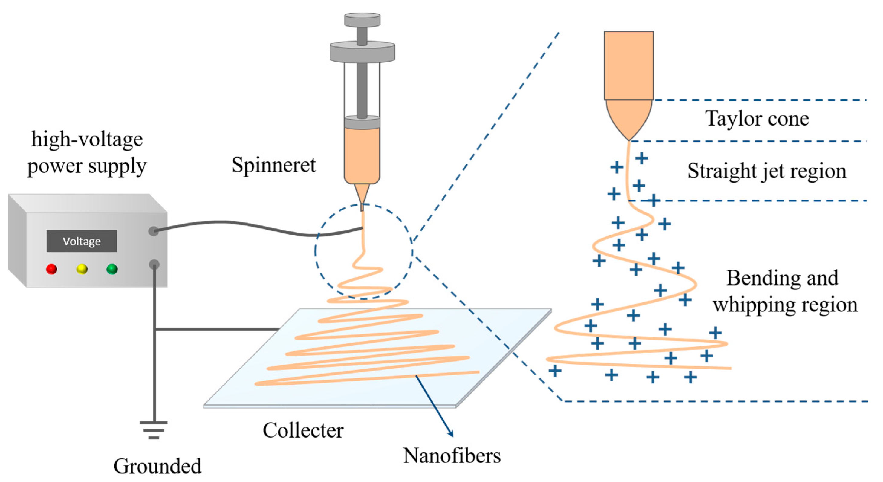
3.2.1. Steam-Induced Phase Separation (VIPS)
3.2.2. Thermally Induced Phase Separation (TIPS)

3.2.3. Nonsolvent-Induced Phase Separation (NIPS)
4. Applications of Electrospun Porous Nanofibers
4.1. Air Purification
4.1.1. Air Filtration
4.1.2. Air Adsorption Separation
4.2. Water Treatment
4.2.1. Membrane Filtration
4.2.2. Oil–Water Separation
4.2.3. Adsorption
4.2.4. Photocatalysis
4.3. Energy Storage
4.4. Biomedicine
4.5. Other Applications

5. Conclusions and Perspectives
Author Contributions
Funding
Institutional Review Board Statement
Data Availability Statement
Conflicts of Interest
References
- Li, M.; Su, L.; Wang, H.; Wan, P.; Guo, P.; Cai, Z.; Gao, H.; Zhang, Z.; Lu, D. Stretchable and compressible Si3N4 nanofiber sponge with aligned microstructure for highly efficient particulate matter filtration under high-velocity airflow. Small 2021, 17, 2100556. [Google Scholar] [CrossRef]
- Nadaf, A.; Gupta, A.; Hasan, N.; Fauziya; Ahmad, S.; Kesharwani, P.; Ahmad, F.J. Recent update on electrospinning and electrospun nanofibers: Current trends and their applications. RSC Adv. 2022, 12, 23808–23828. [Google Scholar] [CrossRef]
- Yu, D.-G.; Du, Y.; Chen, J.; Song, W.; Zhou, T. A Correlation Analysis between Undergraduate Students’ Safety Behaviors in the Laboratory and Their Learning Efficiencies. Behav. Sci. 2023, 13, 127. [Google Scholar] [CrossRef]
- Bai, Y.; Liu, Y.; Lv, H.; Shi, H.; Zhou, W.; Liu, Y.; Yu, D.-G. Processes of electrospun polyvinylidene fluoride-based nanofibers, their piezoelectric properties, and several fantastic applications. Polymers 2022, 14, 4311. [Google Scholar] [CrossRef] [PubMed]
- Huang, X.; Jiang, W.; Zhou, J.; Yu, D.-G.; Liu, H. The applications of ferulic-acid-loaded fibrous films for fruit preservation. Polymers 2022, 14, 4947. [Google Scholar] [CrossRef]
- Zhou, Y.; Wang, M.; Yan, C.; Liu, H.; Yu, D.-G. Advances in the application of electrospun drug-loaded nanofibers in the treatment of oral ulcers. Biomolecules 2022, 12, 1254. [Google Scholar] [CrossRef] [PubMed]
- Xu, X.; Lv, H.; Zhang, M.; Wang, M.; Zhou, Y.; Liu, Y.; Yu, D.-G. Recent progress in electrospun nanofibers and their applications in heavy metal wastewater treatment. Front. Chem. Sci. Eng. 2023. [Google Scholar] [CrossRef]
- Zhao, P.; Chen, W.; Feng, Z.; Liu, Y.; Liu, P.; Xie, Y.; Yu, D.-G. Electrospun nanofibers for periodontal treatment: A recent progress. Int. J. Nanomed. 2022, 17, 4137–4162. [Google Scholar] [CrossRef]
- Sivan, M.; Madheswaran, D.; Hauzerova, S.; Novotny, V.; Hedvicakova, V.; Jencova, V.; Kostakova, E.K.; Schindler, M.; Lukas, D. AC electrospinning: Impact of high voltage and solvent on the electrospinnability and productivity of polycaprolactone electrospun nanofibrous scaffolds. Mater. Today Chem. 2022, 26, 101025. [Google Scholar] [CrossRef]
- Smółka, K.; Firych-Nowacka, A.; Wiak, S. Analysis of the electrostatic field distribution to improve the electrospinning process-practical tips. J. Comput. Sci. 2022, 59, 101542. [Google Scholar] [CrossRef]
- Li, X.; Niu, X.; Chen, Y.; Yuan, K.; He, W.; Yang, S.; Tang, T.; Yu, D.-G. Electrospraying micro-nano structures on chitosan composite coatings for enhanced antibacterial effect. Prog. Org. Coat. 2023, 174, 107310. [Google Scholar] [CrossRef]
- Han, W.; Wang, L.; Li, Q.; Ma, B.; He, C.; Guo, X.; Nie, J.; Ma, G. A Review: Current status and Emerging developments on natural polymer-based electrospun fbers. Macromol. Rapid Commun. 2022, 43, 2200456. [Google Scholar] [CrossRef]
- Avossa, J.; Herwig, G.; Toncelli, C.; Itel, F.; Rossi, R.M. Electrospinning based on benign solvents: Current definitions, implications and strategies. Green Chem. 2022, 24, 2347–2375. [Google Scholar] [CrossRef]
- Kang, S.; Hou, S.; Chen, X.; Yu, D.-G.; Wang, L.; Li, X.; Williams, R.G. Energy-saving electrospinning with a concentric teflon-core rod spinneret to create medicated nanofibers. Polymers 2020, 12, 2421. [Google Scholar] [CrossRef]
- Wang, Y.; Yu, D.-G.; Liu, Y.; Liu, Y.-N. Progress of electrospun nanofibrous carriers for modifications to drug release profiles. J. Funct. Biomater. 2022, 13, 289. [Google Scholar] [CrossRef] [PubMed]
- Yu, D.-G.; Li, Q.; Song, W.; Xu, L.; Zhang, K.; Zhou, T. Advanced technique-based combination of innovation education and safety education in higher education. J. Chem. Educ. 2023, 100. [Google Scholar] [CrossRef]
- Mailley, D.; Hébraud, A.; Schlatter, G. A Review on the impact of humidity during electrospinning: From the nanofiber structure engineering to the applications. Macromol. Mater. Eng. 2021, 306, 2100115. [Google Scholar] [CrossRef]
- Abbas, D.; Mu’min, M.S.; Bonanno, M.; Thiele, S.; Böhm, T. Active solution heating and cooling in electrospinning enabling spinnability from various solvents. J. Appl. Polym. Sci. 2022, 139, e52730. [Google Scholar] [CrossRef]
- Jiang, W.; Zhao, P.; Song, W.; Wang, M.; Yu, D.-G. Electrospun zein/polyoxyethylene core-sheath ultrathin fibers and their antibacterial food packaging applications. Biomolecules 2022, 12, 1110. [Google Scholar] [CrossRef] [PubMed]
- Xu, H.; Zhang, F.; Wang, M.; Lv, H.; Yu, D.-G.; Liu, X.; Shen, H. Electrospun hierarchical structural films for effective wound healing. Biomater. Adv. 2022, 136, 212795. [Google Scholar] [CrossRef] [PubMed]
- Liu, H.; Bai, Y.; Huang, C.; Wang, Y.; Ji, Y.; Du, Y.; Xu, L.; Yu, D.-G.; Bligh, S.W.A. Recent progress of electrospun herbal medicine nanofibers. Biomolecules 2023, 13, 184. [Google Scholar] [CrossRef]
- Sahoo, S.K.; Panigrahi, G.K.; Dhal, J.P.; Sahoo, J.K.; Behera, A.K.; Panda, P.C.; Patel, P.; Mund, S.K.; Muduli, S.M.; Panda, L. Co-axial electrospun hollow MgO nanofibers for efficient removal of fluoride ions from water. Colloids Surf. A 2022, 652, 129877. [Google Scholar] [CrossRef]
- Mubarak, N.; Rehman, F.; Ihsan-Ul-Haq, M.; Xu, M.; Li, Y.; Zhao, Y.; Luo, Z.; Huang, B.; Kim, J.-K. Highly sodiophilic, defect-rich, lignin-derived skeletal carbon nanofiber host for sodium metal batteries. Adv. Energy Mater. 2022, 12, 2103904. [Google Scholar] [CrossRef]
- Lu, T.; Cui, J.; Qu, Q.; Wang, Y.; Zhang, J.; Xiong, R.; Ma, W.; Huang, C. Multistructured electrospun nanofibers for air filtration: A review. ACS Appl. Mater. Inter. 2021, 13, 23293–23313. [Google Scholar] [CrossRef]
- Song, W.; Zhang, M.; Huang, X.; Chen, B.; Ding, Y.; Zhang, Y.; Yu, D.G.; Kim, I. Smart l-borneol-loaded hierarchical hollow polymer nanospheres with antipollution and antibacterial capabilities. Mater. Today Chem. 2022, 26, 101252. [Google Scholar] [CrossRef]
- Li, C.; Yang, J.; He, W.; Xiong, M.; Niu, X.; Li, X.; Yu, D.-G. A review on fabrication and application of tunable hybrid micro–nano array surfaces. Adv. Mater. Interfaces 2023, 10, 2202160. [Google Scholar] [CrossRef]
- Du, L.; Gao, X.Y.; Li, Z.; Yong, G.Y.; Wen, Z.; Yang, C.C.; Jiang, Q. Metal-organic frameworks derived Co/N-doped carbon nanonecklaces as high-efficient oxygen reduction reaction electrocatalysts. Int. J. Hydrogen Energy 2022, 47, 39133–39145. [Google Scholar] [CrossRef]
- Du, X.; Zhou, Z.; Zhang, Z.; Yao, L.; Zhang, Q.; Yang, H. Porous, multi-layered piezoelectric composites based on highly oriented PZT/PVDF electrospinning fibers for high-performance piezoelectric nanogenerators. J. Adv. Ceram. 2022, 11, 331–344. [Google Scholar] [CrossRef]
- Zhang, J.; Li, L.; Chen, J.; He, N.; Yu, K.; Liang, C. Controllable SnO2/ZnO@PPy hollow nanotubes prepared by electrospinning technology used as anode for lithium ion battery. J. Phys. Chem. Solids 2021, 150, 109861. [Google Scholar] [CrossRef]
- Zhang, Y.; Han, S.; Wang, M.; Liu, S.; Liu, G.; Meng, X.; Xu, Z.; Wang, M.; Qiao, G. Electrospun Cu-doped In2O3 hollow nanofibers with enhanced H2S gas sensing performance. J. Adv. Ceram. 2022, 11, 427–442. [Google Scholar] [CrossRef]
- Asare, K.; Hasan, M.F.; Shahbazi, A.; Zhang, L. A comparative study of porous and hollow carbon nanofibrous structures from electrospinning for supercapacitor electrode material development. Surf. Interfaces 2021, 26, 101386. [Google Scholar] [CrossRef]
- Peng, L.; Wang, J.; Guo, S.; Li, C. Exploratory construction of Co/Co3O4-Ni/NiO heterointerface modified macroporous interconnected hollow carbon nanofibers towards efficient and flexible electrocatalysis. Chem. Eng. J. 2022, 450, 138252. [Google Scholar] [CrossRef]
- Lv, H.; Guo, S.; Zhang, G.; He, W.; Wu, Y.; Yu, D.-G. Electrospun structural hybrids of acyclovir-polyacrylonitrile at acyclovir for modifying drug release. Polymers 2021, 13, 4286. [Google Scholar] [CrossRef] [PubMed]
- Jiang, W.; Zhang, X.; Liu, P.; Zhang, Y.; Song, W.; Yu, D.-G.; Lu, X. Electrospun healthcare nanofibers from medicinal liquor of Phellinus igniarius. Adv. Compos. Hybrid Mater. 2022, 5, 3045–3056. [Google Scholar] [CrossRef]
- Wang, M.; Hou, J.; Yu, D.-G.; Li, S.; Zhu, J.; Chen, Z. Electrospun tri-layer nanodepots for sustained release of acyclovir. J. Alloys Compd. 2020, 846, 156471. [Google Scholar] [CrossRef]
- Ge, R.; Ji, Y.; Ding, Y.; Huang, C.; He, H.; Yu, D.-G. Electrospun self-emulsifying core-shell nanofibers for effective delivery of paclitaxel. Front. Bioeng. Biotechnol. 2023, 11, 1112338. [Google Scholar] [CrossRef]
- Yu, D.-G.; Zhao, P. The key elements for biomolecules to biomaterials and to bioapplications. Biomolecules 2022, 12, 1234. [Google Scholar] [CrossRef] [PubMed]
- Huang, C.; Xu, X.; Fu, J.; Yu, D.-G.; Liu, Y. Recent progress in electrospun polyacrylonitrile nanofiber-based wound dressing. Polymers 2022, 14, 32. [Google Scholar] [CrossRef]
- Cao, Q.; Meng, X.; Tan, S.; Xin, Z.; Turng, L.-S.; Li, J.; Yao, Z.; Zhai, Z.; Duan, R. Electrospun bead-in-string fibrous membrane prepared from polysilsesquioxane-immobilising poly(lactic acid) with low filtration resistance for air filtration. J. Polym. Res. 2020, 27, 5. [Google Scholar] [CrossRef]
- Han, W.; Rao, D.; Gao, H.; Yang, X.; Fan, H.; Li, C.; Dong, L.; Meng, H. Green-solvent-processable biodegradable poly(lactic acid) nanofibrous membranes with bead-on-string structure for effective air filtration: “Kill two birds with one stone”. Nano Energy 2022, 97, 107237. [Google Scholar] [CrossRef]
- Cai, M.; He, H.; Zhang, X.; Yan, X.; Li, J.; Chen, F.; Yuan, D.; Ning, X. Efficient synthesis of PVDF/PI side-by-side bicomponent nanofiber membrane with enhanced mechanical strength and good thermal stability. Nanomaterials 2019, 9, 39. [Google Scholar] [CrossRef]
- Chiu, C.-W.; Huang, C.-Y.; Li, J.-W.; Li, C.L. Flexible hybrid electronics nanofiber electrodes with excellent stretchability and highly stable electrical conductivity for smart clothing. ACS Appl. Mater. Inter. 2022, 14, 42441–42453. [Google Scholar] [CrossRef]
- Huang, C.; Thomas, N.L. Fabrication of porous fibers via electrospinning: Strategies and applications. Polym. Rev. 2020, 60, 595–647. [Google Scholar] [CrossRef]
- Liu, R.; Hou, L.; Yue, G.; Li, H.; Zhang, J.; Liu, J.; Miao, B.; Wang, N.; Bai, J.; Cui, Z.; et al. Progress of fabrication and applications of electrospun hierarchically porous nanofibers. Adv. Fiber Mater. 2022, 4, 604–630. [Google Scholar] [CrossRef]
- Feng, Z.; Yang, S.; Jianyong, Y.; Bin, D. Electrospun porous engineered nanofiber materials: A versatile medium for energy and environmental applications. Chem. Eng. J. 2022, 456, 140989. [Google Scholar]
- Min, T.; Zhou, L.; Sun, X.; Du, H.; Zhu, Z.; Wen, Y. Electrospun functional polymeric nanofibers for active food packaging: A review. Food Chem. 2022, 391, 133239. [Google Scholar] [CrossRef] [PubMed]
- Wu, J.; Xu, F.; Li, S.; Ma, P.; Zhang, X.; Liu, Q.; Fu, R.; Wu, D. Porous polymers as multifunctional material platforms toward task-specific applications. Adv. Mater. 2019, 31, 1802922. [Google Scholar] [CrossRef]
- Tan, W.-b.; Luo, D.; Song, W.; Lu, Y.-y.; Cheng, N.; Zhang, J.-b.; Huang, T.; Wang, Y. Polydopamine-assisted polyethyleneimine grafting on electrospun cellulose acetate/TiO2 fibers towards highly efficient removal of Cr(VI). Eur. Polym. J. 2022, 180, 111632. [Google Scholar] [CrossRef]
- Zhang, C.-L.; Lu, B.-R.; Cao, F.-H.; Wu, Z.-Y.; Zhang, W.; Cong, H.-P.; Yu, S.-H. Electrospun metal-organic framework nanoparticle fibers and their derived electrocatalysts for oxygen reduction reaction. Nano Energy 2019, 55, 226–233. [Google Scholar] [CrossRef]
- Zhang, Y.; Kong, D.; Bo, L.; Shi, W.; Guan, X.; Wang, Y.; Lei, Z.; Tong, J. Electrospinning preparation of N, P dual-doped molybdenum carbide/porous carbon fibers with highly improved electrocatalytic activity for hydrogen evolution reaction. ACS Appl. Energy Mater. 2021, 4, 13051–13060. [Google Scholar] [CrossRef]
- Li, Z.; Zhang, J.-w.; Yu, L.-g.; Zhang, J.-w. Electrospun porous nanofibers for electrochemical energy storage. J. Mater. Sci. 2017, 52, 6173–6195. [Google Scholar] [CrossRef]
- Purushothaman, A.E.; Thakur, K.; Kandasubramanian, B. Development of highly porous, electrostatic force assisted nanofiber fabrication for biological applications. Int. J. Polym. Mater. Polym. 2020, 69, 477–504. [Google Scholar] [CrossRef]
- Xue, F.; Lin, X.; Li, Y.; Zhang, Z.; Lin, J.; Li, Q. Electrospun of CoSn nanoboxes@carbon nanotubes as free-standing anodes for high-performance lithium-/potassium-ion batteries. Appl. Surf. Sci. 2021, 565, 150599. [Google Scholar] [CrossRef]
- Kumeria, T. Advances on porous nanomaterials for biomedical application (drug delivery, sensing, and tissue engineering). ACS Biomater.-Sci. Eng. 2022, 8, 4025–4027. [Google Scholar] [CrossRef]
- El-Samak, A.A.; Ponnamma, D.; Hassan, M.K.; Al-Maadeed, M.A.A. A stable porous vessel for photocatalytic degradation of Azocarmine G dye. Microporous Mesoporous Mater. 2022, 341, 111994. [Google Scholar] [CrossRef]
- Asano, N.; Sugihara, S.; Suye, S.-i.; Fujita, S. Electrospun porous nanofibers with imprinted patterns induced by phase separation of immiscible polymer blends. ACS Omega 2022, 7, 19997–20005. [Google Scholar] [CrossRef]
- Kong, Q.; Li, Z.; Ren, X.; Gu, H.; Ma, W. The surface morphology and dynamic impact properties with rebounding and splashing of water droplet on phase separation and breath figure assisted electrospinning films. Des. Monomers Polym. 2021, 24, 162–172. [Google Scholar] [CrossRef]
- Min, T.; Zhou, L.; Sun, X.; Du, H.; Bian, X.; Zhu, Z.; Wen, Y. Enzyme-responsive food packaging system based on pectin-coated poly (lactic acid) nanofiber films for controlled release of thymol. Food Res. Int. 2022, 157, 111256. [Google Scholar] [CrossRef] [PubMed]
- Megelski, S.; Stephens, J.S.; Chase, D.B.; Rabolt, J.F. Micro-and nanostructured surface morphology on electrospun polymer fibers. Macromolecules 2002, 35, 8456–8466. [Google Scholar] [CrossRef]
- Lu, P.; Xia, Y. Maneuvering the internal porosity and surface morphology of electrospun polystyrene yarns by controlling the solvent and relative humidity. Abstr. Pap. Am. Chem. Soc. 2013, 29, 7070–7078. [Google Scholar] [CrossRef]
- Zaarour, B.; Zhang, W.; Zhu, L.; Jin, X.Y.; Huang, C. Maneuvering surface structures of polyvinylidene fluoride nanofibers by controlling solvent systems and polymer concentration. Text. Res. J. 2019, 89, 2406–2422. [Google Scholar] [CrossRef]
- Wang, Q.; Zhang, Z.; Liu, L.; Bai, L.; Bao, R.-Y.; Yang, M.-B.; Yang, W. Degradable ultrathin high-performance photocatalytic hydrogen generator from porous electrospun composite fiber membrane with enhanced light absorption ability. J. Mater. Chem. A 2021, 9, 10277–10288. [Google Scholar] [CrossRef]
- Cao, X.; Chen, W.; Zhao, P.; Yang, Y.; Yu, D.-G. Electrospun porous nanofibers: Pore-forming mechanisms and applications for photocatalytic degradation of organic pollutants in wastewater. Polymers 2022, 14, 3990. [Google Scholar] [CrossRef] [PubMed]
- Wang, B.; Wang, Y.; Lei, Y.; Wu, N.; Gou, Y.; Han, C. Tailoring of porous structure in macro-meso-microporous SiC ultrathin fibers via electrospinning combined with polymer-derived ceramics route. Mater. Manuf. Process. 2016, 31, 1357–1365. [Google Scholar] [CrossRef]
- Li, Y.; Zhang, X.; Si, Y.; Yu, J.; Ding, B. Super-elastic fluorinated polyurethane nanofibrous membranes with simultaneously waterproof and breathable performance. ACS Appl. Polym. Mater. 2022, 4, 5557–5565. [Google Scholar] [CrossRef]
- Kossyvaki, D.; Barbetta, A.; Contardi, M.; Bustreo, M.; Dziza, K.; Lauciello, S.; Athanassiou, A.; Fragouli, D. Highly porous curcumin-loaded polymer mats for rapid detection of volatile amines. ACS Appl. Polym. Mater. 2022, 4, 4464–4475. [Google Scholar] [CrossRef]
- Katsogiannis, K.A.G.; Vladisavljević, G.T.; Georgiadou, S. Porous electrospun polycaprolactone (PCL) fibres by phase separation. Eur. Polym. J. 2015, 69, 284–295. [Google Scholar] [CrossRef]
- Rezabeigi, E.; Sta, M.; Swain, M.; McDonald, J.; Demarquette, N.R.; Drew, R.A.L.; Wood-Adams, P.M. Electrospinning of porous polylactic acid fibers during nonsolvent induced phase separation. J. Appl. Polym. Sci. 2017, 134, 44862. [Google Scholar] [CrossRef]
- Song, J.; Zhang, B.; Lu, Z.; Xing, Z.; Liu, T.; Wei, W.; Zia, Q.; Pan, K.; Gong, R.H.; Bian, L.; et al. Hierarchical porous Poly(L-lactic acid) nanofibrous membrane for ultrafine particulate aerosol filtration. ACS Appl. Mater. Interf. 2019, 11, 46261–46268. [Google Scholar] [CrossRef]
- Li, H.; Wang, Z.; Zhang, H.; Pan, Z. Nanoporous PLA/(chitosan nanoparticle) composite fibrous membranes with excellent air filtration and antibacterial performance. Polymers 2018, 10, 1085. [Google Scholar] [CrossRef]
- Yoon, C.K.; Park, B.K.; Lee, W.I. Characteristics of micro-glass bead/PLA porous composite prepared by electrospinning. Adv. Compos. Mater. 2018, 27, 183–193. [Google Scholar] [CrossRef]
- Qi, Z.; Yu, H.; Chen, Y.; Zhu, M. Highly porous fibers prepared by electrospinning a ternary system of nonsolvent/solvent/poly(L-lactic acid). Mater. Lett. 2009, 63, 415–418. [Google Scholar] [CrossRef]
- Yin, J.; Xu, L.; Ahmed, A. Batch preparation and characterization of electrospun porous polylactic acid-based nanofiber membranes for antibacterial wound dressing. Adv. Fiber Mater. 2022, 4, 832–844. [Google Scholar] [CrossRef]
- Prasad, G.; Liang, J.-W.; Zhao, W.; Yao, Y.; Tao, T.; Liang, B.; Lu, S.-G. Enhancement of solvent uptake in porous PVDF nanofibers derived by a water-mediated electrospinning technique. J. Mater. 2021, 7, 244–253. [Google Scholar] [CrossRef]
- Lin, J.; Ding, B.; Yang, J.; Yu, J.; Sun, G. Subtle regulation of the micro- and nanostructures of electrospun polystyrene fibers and their application in oil absorption. Nanoscale 2012, 4, 176–182. [Google Scholar] [CrossRef]
- Sabetzadeh, N.; Gharehaghaji, A.A.; Javanbakht, M. Porous PAN micro/nanofiber membranes with potential application as lithium-ion battery separators: Physical, morphological and thermal properties. J. Polym. Res. 2019, 26, 20. [Google Scholar] [CrossRef]
- Yu, X.; Xiang, H.; Long, Y.; Zhao, N.; Zhang, X.; Xu, J. Preparation of porous polyacrylonitrile fibers by electrospinning a ternary system of PAN/DMF/H2O. Mater. Lett. 2010, 64, 2407–2409. [Google Scholar] [CrossRef]
- Feng, Z.-Q.; Yuan, X.; Wang, T. Porous polyacrylonitrile/graphene oxide nanofibers designed for high efficient adsorption of chromium ions (VI) in aqueous solution. Chem. Eng. J. 2020, 392, 123730. [Google Scholar] [CrossRef]
- Ji, S.-H.; Yun, J.-S. Highly porous-cellulose-acetate-nanofiber filters fabricated by nonsolvent-induced phase separation during electrospinning for PM2.5 capture. Nanomaterials 2022, 12, 404. [Google Scholar] [CrossRef]
- Zheng, X.; Liu, Y.; Liu, X.; Li, Q.; Zheng, Y. A novel PVDF-TiO2@g-C3N4 composite electrospun fiber for efficient photocatalytic degradation of tetracycline under visible light irradiation. Ecotoxicol. Environ. Saf. 2021, 210, 111866. [Google Scholar] [CrossRef]
- Liang, Y.; Lin, C.; Guan, J.; Li, Y. Silver nanoparticle-immobilized porous POM/PLLA nanofibrous membranes: Efficient catalysts for reduction of 4-nitroaniline. RSC Adv. 2017, 7, 7460–7468. [Google Scholar] [CrossRef]
- Moon, S.; Choi, J.; Farris, R.J. Highly porous polyacrylonitrile/polystyrene nanofibers by electrospinning. Fiber Polym. 2008, 9, 276–280. [Google Scholar] [CrossRef]
- Lyoo, W.S.; Youk, J.H.; Lee, S.W.; Park, W.H. Preparation of porous ultra-fine poly(vinyl cinnamate) fibers. Mater. Lett. 2005, 59, 3558–3562. [Google Scholar] [CrossRef]
- Peng, M.; Li, D.; Shen, L.; Chen, Y.; Zheng, Q.; Wang, H. Nanoporous structured submicrometer carbon fibers prepared via solution electrospinning of polymer blends. Langmuir 2006, 22, 9368–9374. [Google Scholar] [CrossRef]
- Li, Z.; Zhang, J.T.; Chen, Y.M.; Li, J.; Lou, X.W. Pie-like electrode design for high-energy density lithium-sulfur batteries. Nat. Commun. 2015, 6, 8850. [Google Scholar] [CrossRef] [PubMed]
- Shan, H.; Si, Y.; Yu, J.; Ding, B. Facile access to highly flexible and mesoporous structured silica fibrous membranes for tetracyclines removal. Chem. Eng. J. 2021, 417, 129211. [Google Scholar] [CrossRef]
- Song, J.; Guan, R.; Xie, M.; Dong, P.; Yang, X.; Zhang, J. Advances in electrospun TiO2 nanofibers: Design, construction, and applications. Chem. Eng. J. 2022, 431, 134343. [Google Scholar] [CrossRef]
- Huang, J.; Li, J.; Xu, X.; Hua, L.; Lu, Z. In Situ Loading of polypyrrole onto aramid nanofiber and carbon nanotube aerogel fibers as physiology and motion sensors. ACS Nano 2022, 16, 8161–8171. [Google Scholar] [CrossRef]
- Hong, G.; Li, X.; Shen, L.; Wang, M.; Wang, C.; Yu, X.; Wang, X. High recovery of lead ions from aminated polyacrylonitrile nanofibrous affinity membranes with micro/nano structure. J. Hazard. Mater. 2015, 295, 161–169. [Google Scholar] [CrossRef]
- Ning, J.; Zhang, X.; Yang, H.; Xu, Z.-L.; Wei, Y.-M. Preparation of porous PVDF nanofiber coated with Ag NPs for photocatalysis application. Fibers Polym. 2016, 17, 21–29. [Google Scholar] [CrossRef]
- Gao, J.-F.; Hu, M.-J.; Li, W.; Wong, J.S.-P.; Li, R.K.Y. Morphological evolution from porous nanofibers to rice like nanobeans. Mater. Lett. 2014, 128, 110–113. [Google Scholar] [CrossRef]
- Guan, J.; Li, J.; Li, Y. Electrospun nanofibers with both surface nanopores and internal interpenetrated nanochannels for oil absorption. RSC Adv. 2016, 6, 33781–33788. [Google Scholar] [CrossRef]
- Dong, Y.; Lin, H.; Zhou, D.; Niu, H.; Jin, Q.; Qu, F. Synthesis of mesoporous graphitic carbon fibers with high performance for supercapacitor. Electrochim. Acta 2015, 159, 116–123. [Google Scholar] [CrossRef]
- Nan, D.; Wang, J.-G.; Huang, Z.-H.; Wang, L.; Shen, W.; Kang, F. Highly porous carbon nanofibers from electrospun polyimide/SiO2 hybrids as an improved anode for lithium-ion batteries. Electrochem. Commun. 2013, 34, 52–55. [Google Scholar] [CrossRef]
- Liu, Z.; Fu, D.; Liu, F.; Han, G.; Liu, C.; Chang, Y.; Xiao, Y.; Li, M.; Li, S. Mesoporous carbon nanofibers with large cage-like pores activated by tin dioxide and their use in supercapacitor and catalyst support. Carbon 2014, 70, 295–307. [Google Scholar] [CrossRef]
- Cheng, L.; He, J.; Jin, Y.; Chen, H.; Chen, M. Single-walled carbon nanotube embedded porous carbon nanofiber with enhanced electrochemical capacitive performance. Mater. Lett. 2015, 144, 123–126. [Google Scholar] [CrossRef]
- Nie, D.; Wang, P.; Zang, C.; Zhang, G.; Li, S.; Liu, R.; Zhang, Y.; Li, G.; Luo, Y.; Zhang, W.; et al. Preparation of ZnO-incorporated porous carbon nanofibers and adsorption performance investigation on methylene blue. ACS Omega 2022, 7, 2198–2204. [Google Scholar] [CrossRef]
- Liu, J.; Chang, M.-J.; Du, H.-L. Facile preparation of cross-linked porous poly(vinyl alcohol) nanofibers by electrospinning. Mater. Lett. 2016, 183, 318–321. [Google Scholar] [CrossRef]
- Chen, Y.; Lu, Z.; Zhou, L.; Mai, Y.-W.; Huang, H. Triple-coaxial electrospun amorphous carbon nanotubes with hollow graphitic carbon nanospheres for high- performance Li ion batteries. Energy Environ. Sci. 2012, 5, 7898–7902. [Google Scholar] [CrossRef]
- Chen, Y.; Li, X.; Park, K.; Song, J.; Hong, J.; Zhou, L.; Mai, Y.-W.; Huang, H.; Goodenough, J.B. Hollow carbon-nanotube/carbon-nanofiber hybrid anodes for Li-ion batteries. J. Am. Chem. Soc. 2013, 135, 16280–16283. [Google Scholar] [CrossRef]
- Zhang, L.; Jiang, Y.; Wang, L.; Zhang, C.; Liu, S. Hierarchical porous carbon nanofibers as binder-free electrode for high-performance supercapacitor. Electrochim. Acta 2016, 196, 189–196. [Google Scholar] [CrossRef]
- Mehraban, M.; Zadhoush, A.; Ravandi, S.A.H.; Bagheri, R.; Tehrani, A.H. Preparation of porous nanofibers from electrospun Polyacrylonitrile/Calcium carbonate composite nanofibers using porogen leaching technique. J. Appl. Polym. Sci. 2013, 128, 926–933. [Google Scholar] [CrossRef]
- Adhikari, S.P.; Pant, H.R.; Mousa, H.M.; Lee, J.; Kim, H.J.; Park, C.H.; Kim, C.S. Synthesis of high porous electrospun hollow TiO2 nanofibers for bone tissue engineering application. J. Ind. Eng. Chem. 2016, 35, 75–82. [Google Scholar] [CrossRef]
- Karthikeyan, K.K.; Biji, P. A novel biphasic approach for direct fabrication of highly porous, flexible conducting carbon nanofiber mats from polyacrylonitrile (PAN)/NaHCO3 nanocomposite. Microporous Mesoporous Mater. 2016, 224, 372–383. [Google Scholar] [CrossRef]
- Mokhtari-Shourijeh, Z.; Montazerghaem, L.; Olya, M.E. Preparation of porous nanofibers from electrospun Polyacrylonitrile/Polyvinylidene fluoride composite nanofibers by inexpensive salt using for dye adsorption. J. Polym. Environ. 2018, 26, 3550–3563. [Google Scholar] [CrossRef]
- Wang, Y.; Wang, B.; Wang, G.; Yin, T.; Yu, Q. A novel method for preparing electrospun fibers with nano-/micro-scale porous structures. Polym. Bull. 2009, 63, 259–265. [Google Scholar] [CrossRef]
- Gupta, A.; Saquing, C.D.; Afshari, M.; Tonelli, A.E.; Khan, S.A.; Kotek, R. Porous nylon-6 fibers via a novel salt-induced electrospinning method. Macromolecules 2009, 42, 709–715. [Google Scholar] [CrossRef]
- Nagamine, S.; Matsumoto, T.; Hikima, Y.; Ohshima, M. Fabrication of porous carbon nanofibers by phosphate-assisted carbonization of electrospun poly(vinyl alcohol) nanofibers. Mater. Res. Bull. 2016, 79, 8–13. [Google Scholar] [CrossRef]
- Li, X.S.; Nie, G.Y. Nano-porous ultra-high specific surface ultrafine fibers. Chin. Sci. Bull. 2004, 49, 2368–2371. [Google Scholar] [CrossRef]
- Chen, P.-Y.; Tung, S.-H. One-step electrospinning to produce nonsolvent-induced macroporous fibers with ultrahigh oil adsorption capability. Macromolecules 2017, 50, 2528–2534. [Google Scholar] [CrossRef]
- Pai, C.-L.; Boyce, M.C.; Rutledge, G.C. Morphology of porous and wrinkled fibers of polystyrene electrospun from dimethylformamide. Macromolecules 2009, 42, 2102–2114. [Google Scholar] [CrossRef]
- Li, L.; Jiang, Z.; Li, M.; Li, R.; Fang, T. Hierarchically structured PMMA fibers fabricated by electrospinning. RSC Adv. 2014, 4, 52973–52985. [Google Scholar] [CrossRef]
- McCann, J.T.; Marquez, M.; Xia, Y.N. Highly porous fibers by electrospinning into a cryogenic liquid. J. Am. Chem. Soc. 2006, 128, 1436–1437. [Google Scholar] [CrossRef]
- Li, W.; Shi, L.; Zhou, K.; Zhang, X.; Ullah, I.; Ou, H.; Zhang, W.; Wu, T. Facile fabrication of porous polymer fibers via cryogenic electrospinning system. J. Mater. Process. Tech. 2019, 266, 551–557. [Google Scholar] [CrossRef]
- Ye, X.-Y.; Lin, F.-W.; Huang, X.-J.; Liang, H.-Q.; Xu, Z.-K. Polymer fibers with hierarchically porous structure: Combination of high temperature electrospinning and thermally induced phase separation. RSC Adv. 2013, 3, 13851–13858. [Google Scholar] [CrossRef]
- Lubasova, D.; Martinova, L. Controlled morphology of morous polyvinyl butyral manofibers. J. Nanomater. 2011, 2011, 292516. [Google Scholar] [CrossRef]
- Nayani, K.; Katepalli, H.; Sharma, C.S.; Sharma, A.; Patil, S.; Venkataraghavan, R. Electrospinning combined with nonsolvent-induced phase separation to fabricate highly porous and hollow submicrometer polymer fibers. Ind. Eng. Chem. Res. 2012, 51, 1761–1766. [Google Scholar] [CrossRef]
- Shen, W.; Zhang, G.; Li, Y.; Fan, G. Effects of the glycerophosphate-polylactic copolymer formation on electrospun fibers. Appl. Surf. Sci. 2018, 443, 236–243. [Google Scholar] [CrossRef]
- Tang, N.; Si, Y.; Yu, J.; Ding, B. Leaf vein-inspired microfiltration membrane based on ultrathin nanonetworks. Environ. Sci.-Nano 2020, 7, 2644–2653. [Google Scholar] [CrossRef]
- He, T.-S.; Yu, X.-D.; Bai, T.-J.; Li, X.-Y.; Fu, Y.-R.; Cai, K.-D. Porous carbon nanofibers derived from PAA-PVP electrospun fibers for supercapacitor. Ionics 2020, 26, 4103–4111. [Google Scholar] [CrossRef]
- Dong, T.; Ul Arifeen, W.; Choi, J.; Yoo, K.; Ko, T. Surface-modified electrospun polyacrylonitrile nano-membrane for a lithium-ion battery separator based on phase separation mechanism. Chem. Eng. J. 2020, 398, 125646. [Google Scholar] [CrossRef]
- Zhao, Y.; Lai, Q.; Wang, Y.; Zhu, J.; Liang, Y. Interconnected hierarchically porous Fe, N-codoped carbon nanofibers as efficient oxygen reduction catalysts for Zn-air batteries. ACS Appl. Mater. Inter. 2017, 9, 16178–16186. [Google Scholar] [CrossRef] [PubMed]
- Zhang, Y.; Zhang, M.; Cheng, D.; Xu, S.; Du, C.; Xie, L.; Zhao, W. Applications of electrospun scaffolds with enlarged pores in tissue engineering. Biomater. Sci. 2022, 10, 1423–1447. [Google Scholar] [CrossRef] [PubMed]
- Liang, F.-C.; Kuo, C.-C.; Chen, B.-Y.; Cho, C.-J.; Hung, C.-C.; Chen, W.-C.; Borsali, R. RGB-switchable porous electrospun nanofiber chemoprobe-filter prepared from multifunctional copolymers for versatile sensing of PH and heavy metals. ACS Appl. Mater. Inter. 2017, 9, 16381–16396. [Google Scholar] [CrossRef]
- Wu, H.; Kong, J.; Yao, X.; Zhao, C.; Dong, Y.; Lu, X. Polydopamine-assisted attachment of beta-cyclodextrin on porous electrospun fibers for water purification under highly basic condition. Chem. Eng. J. 2015, 270, 101–109. [Google Scholar] [CrossRef]
- Xue, J.; Li, X.; Jin, X.; Wang, X.; Zhen, N.; Song, T.; Lan, T.; Qian, S.; Zhang, H.; Liu, J. Electrocatalytic oxidation of formaldehyde using electrospinning porous zein-based polyimide fibers. Mater. Lett. 2022, 320, 132318. [Google Scholar] [CrossRef]
- Chen, W.; Wang, H.; Lan, W.; Zhang, A.; Liu, C. Fabrication of sugarcane bagasse ester-based porous nanofiber membrane by electrospinning for efficient oil-water separation. Ind. Crops Prod. 2022, 187, 115480. [Google Scholar] [CrossRef]
- Li, C.; Yuan, C.; Zhu, J.; Ni, X.; Li, K.; Wang, L.; Qi, Y.; Ju, A. Fabrication of silicon nanoparticles/porous carbon@porous carbon nanofibers core-shell structured composites as high-performance anodes for lithium-ion batteries. Colloids Surf. A 2022, 655, 129721. [Google Scholar] [CrossRef]
- Liu, C.; Hsu, P.-C.; Lee, H.-W.; Ye, M.; Zheng, G.; Liu, N.; Li, W.; Cui, Y. Transparent air filter for high-efficiency PM2.5 capture. Nat. Commun. 2015, 6, 361. [Google Scholar] [CrossRef]
- Zhang, R.; Liu, C.; Hsu, P.-C.; Zhang, C.; Liu, N.; Zhang, J.; Lee, H.R.; Lu, Y.; Qiu, Y.; Chu, S.; et al. Nanofiber air filters with high-temperature stability for efficient removal from the pollution sources. Nano Lett. 2016, 16, 3642–3649. [Google Scholar] [CrossRef]
- Wang, Z.; Yan, F.; Pei, H.; Yan, K.; Cui, Z.; He, B.; Fang, K.; Li, J. Environmentally-friendly halloysite nanotubes@chitosan/polyvinyl alcohol/non-woven fabric hybrid membranes with a uniform hierarchical porous structure for air filtration. J. Membr. Sci. 2020, 594, 117445. [Google Scholar] [CrossRef]
- Sevilla, M.; Fuertes, A.B. Sustainable porous carbons with a superior performance for CO2 capture. Energy Environ. Sci. 2011, 4, 1765–1771. [Google Scholar] [CrossRef]
- Zainab, G.; Babar, A.A.; Ali, N.; Aboalhassan, A.A.; Wang, X.; Yu, J.; Ding, B. Electrospun carbon nanofibers with multi-aperture/opening porous hierarchical structure for efficient CO2 adsorption. J. Colloid Interf. Sci. 2020, 561, 659–667. [Google Scholar] [CrossRef] [PubMed]
- Yan, J.; Dong, K.; Zhang, Y.; Wang, X.; Aboalhassan, A.A.; Yu, J.; Ding, B. Multifunctional flexible membranes from sponge-like porous carbon nanofibers with high conductivity. Nat. Commun. 2019, 10, 5584. [Google Scholar] [CrossRef] [PubMed]
- Yu, Y.; Ma, Q.; Zhang, J.-b.; Liu, G.-b. Electrospun SiO2 aerogel/polyacrylonitrile composited nanofibers with enhanced adsorption performance of volatile organic compounds. Appl. Surf. Sci. 2020, 512, 145697. [Google Scholar] [CrossRef]
- Yang, X.; Wu, X.; Chen, Z.; Li, W.; Sun, Q.-J.; Guo, Z.; Liang, X.; He, Y. Hierarchically porous N-doped carbon nanofibers derived from ZIF-8/PAN composites for benzene adsorption. J. Appl. Polym. Sci. 2021, 138, 50431. [Google Scholar] [CrossRef]
- Wang, R.; Hu, Q.-h.; Wang, Q.-y.; Xiang, Y.-l.; Huang, S.-h.; Liu, Y.-z.; Li, S.-y.; Chen, Q.-l.; Zhou, Q.-h. Efficiently selective removal of Pb(II) by magnetic ion-imprinted membrane based on polyacrylonitrile electro-spun nanofibers. Sep. Purif. Technol. 2022, 284, 120280. [Google Scholar] [CrossRef]
- Chen, K.; Ling, H.; Liu, H.; Zhao, W.; Xiao, C. Design of robust FEP porous ultrafiltration membranes by electrospinning-sintered technology. Polymers 2022, 14, 3802. [Google Scholar] [CrossRef]
- Deng, Y.-F.; Zhang, D.; Zhang, N.; Huang, T.; Lei, Y.-Z.; Wang, Y. Electrospun stereocomplex polylactide porous fibers toward highly efficient oil/water separation. J. Hazard. Mater. 2021, 407, 124787. [Google Scholar] [CrossRef]
- Lu, T.; Liang, H.; Cao, W.; Deng, Y.; Qu, Q.; Ma, W.; Xiong, R.; Huang, C. Blow-spun nanofibrous composite Self-cleaning membrane for enhanced purification of oily wastewater. J. Colloid Interf. Sci. 2022, 608, 2860–2869. [Google Scholar] [CrossRef] [PubMed]
- Pan, Y.; Li, R.; Li, P.; Wang, Y.; Zhu, Y.; Xu, Z.; Chen, X.; Sun, Z.; Li, C.; Jiang, B. Facile fabrication of flexible, large-sized organic nanoporous membrane by electrospinning technique based on microporous polymer nanoparticles. Microporous Mesoporous Mater. 2021, 317, 110955. [Google Scholar] [CrossRef]
- Yan, J.; Bai, T.; Yue, Y.; Cheng, W.; Bai, L.; Wang, D.; Lu, J.; Cao, M.; Shi, S.Q.; Huan, S.; et al. Nanostructured superior oil-adsorbent nanofiber composites using one-step electrospinning of polyvinylidene fluoride/nanocellulose. Compos. Sci. Technol. 2022, 224, 109490. [Google Scholar] [CrossRef]
- Xu, P.; Wang, Y.; Wang, S.; Dai, W.; Chen, N.; Li, Q. Preparation of polyethyleneimine-modified porous polyacrylonitrile electrospun nanofibers for efficient removal of methyl orange. J. Macromol. Sci. A 2022, 59, 504–512. [Google Scholar] [CrossRef]
- Zhao, R.; Shi, X.; Ma, T.; Rong, H.; Wang, Z.; Cui, F.; Zhu, G.; Wang, C. Constructing mesoporous adsorption channels and MOF-polymer interfaces in electrospun composite fibers for effective removal of emerging organic contaminants. ACS Appl. Mater. Interf. 2021, 13, 755–764. [Google Scholar] [CrossRef]
- Dou, S.; Ke, X.-X.; Zhong, L.-B.; Fan, J.-J.; Chen, J.P.; Zheng, Y.-M. Novel ultraporous polyimide-based hollow carbon nanofiber mat: Its polymer-blend electrospinning preparation strategy and efficient dynamic adsorption for ciprofloxacin removal. Sep. Purif. Technol. 2022, 295, 121341. [Google Scholar] [CrossRef]
- Xu, X.; Zhang, M.; Lv, H.; Zhou, Y.; Yang, Y.; Yu, D.-G. Electrospun polyacrylonitrile-based lace nanostructures and their Cu (II) adsorption. Sep. Purif. Technol. 2022, 288, 120643. [Google Scholar] [CrossRef]
- Zhao, Q.; Yin, M.; Zhang, A.P.; Prescher, S.; Antonietti, M.; Yuan, J. Hierarchically structured nanoporous Poly(Ionic Liquid) membranes: Facile preparation and application in fiber-optic PH sensing. J. Am. Chem. Soc. 2013, 135, 5549–5552. [Google Scholar] [CrossRef]
- Liang, H.-W.; Zhuang, X.; Bruller, S.; Feng, X.; Mullen, K. Hierarchically porous carbons with optimized nitrogen doping as highly active electrocatalysts for oxygen reduction. Nat. Commun. 2014, 5, 4973. [Google Scholar] [CrossRef]
- Qian, M.; Yang, F.; Li, N.; Gao, J.; Chen, X.; Xu, T.; Zhu, Z.; Lu, W.; Chen, W. A novel biodegradable porous graphitic carbon nitride/poly(lactic acid) fiber photocatalyst for efficient elimination of carbamazepine under solar irradiation. Chem. Eng. J. 2021, 414, 128845. [Google Scholar] [CrossRef]
- Xu, Y.; Yuan, D.; Guo, Y.; Chen, S.; Lin, W.; Long, Y.; Bao, J.; He, C.; Cheng, C.; Deng, C.; et al. Superhydrophilic and polyporous nanofibrous membrane with excellent photocatalytic activity and recyclability for wastewater remediation under visible light irradiation. Chem. Eng. J. 2022, 427, 131685. [Google Scholar] [CrossRef]
- Huang, L.; Cheng, J.; Qu, G.; Li, X.; Hu, Y.; Ni, W.; Yuan, D.; Zhang, Y.; Wang, B. Porous carbon nanofibers formed in situ by electrospinning with a volatile solvent additive into an ice water bath for lithium-sulfur batteries. RSC Adv. 2015, 5, 23749–23757. [Google Scholar] [CrossRef]
- Wang, Y.; Yuan, C.; Li, K.; Li, D.; Ju, A. Freestanding porous silicon@heteroatom-doped porous carbon fiber anodes for high-performance Lithium-ion batteries. ACS Appl. Energy Mater. 2022, 5, 11462–11471. [Google Scholar] [CrossRef]
- Shan, C.; Feng, X.; Yang, J.; Yang, X.; Guan, H.-Y.; Argueta, M.; Wu, X.-L.; Liu, D.-S.; Austin, D.J.; Nie, P.; et al. Hierarchical porous carbon pellicles: Electrospinning synthesis and applications as anodes for sodium-ion batteries with an outstanding performance. Carbon 2020, 157, 308–315. [Google Scholar] [CrossRef]
- Liao, R.; Wang, H.; Zhang, W.; Shi, J.; Huang, M.; Shi, Z.; Wei, W.; Li, X.; Liu, S. High-rate sodium storage performance enabled using hollow Co3O4 nanoparticles anchored in porous carbon nanofibers anode. J. Alloys Compd. 2021, 868, 159262. [Google Scholar] [CrossRef]
- Zhu, S.; Huang, A.; Wang, Q.; Xu, Y. MOF-derived porous carbon nanofibers wrapping Sn nanoparticles as flexible anodes for lithium/sodium ion batteries. Nanotechnology 2021, 32, 165401. [Google Scholar] [CrossRef] [PubMed]
- Chen, S.; Gao, J.; Yan, E.; Wang, Y.; Li, Y.; Lu, H.; Fan, L.; Wang, D.; An, Q. A novel porous composite membrane of PHA/PVA via coupling of electrospinning and spin coating for antibacterial applications. Mater. Lett. 2021, 301, 130279. [Google Scholar] [CrossRef]
- Dai, T.; Ma, J.; Ni, S.; Liu, C.; Wang, Y.; Wu, S.; Liu, J.; Weng, Y.; Zhou, D.; Jimenez-Franco, A.; et al. Attapulgite-doped electrospun PCL scaffolds for enhanced bone regeneration in rat cranium defects. Biomater. Adv. 2022, 133, 112656. [Google Scholar] [CrossRef] [PubMed]
- Cheng, G.; Yin, C.; Tu, H.; Jiang, S.; Wang, Q.; Zhou, X.; Xing, X.; Xie, C.; Shi, X.; Du, Y.; et al. Controlled Co-delivery of growth factors through layer-by-layer assembly of core-shell nanofibers for improving bone regeneration. ACS Nano 2019, 13, 6372–6382. [Google Scholar] [CrossRef] [PubMed]
- Chen, Y.; Qiu, Y.; Chen, W.; Wei, Q. Electrospun thymol-loaded porous cellulose acetate fibers with potential biomedical applications. Mater. Sci. Eng. C-Mater. 2020, 109, 110536. [Google Scholar] [CrossRef]
- Chen, Y.; Mensah, A.; Wang, Q.; Li, D.; Qiu, Y.; Wei, Q. Hierarchical porous nanofibers containing thymol/beta-cyclodextrin: Physico-chemical characterization and potential biomedical applications. Mater. Sci. Eng. C-Mater. 2020, 115, 111155. [Google Scholar] [CrossRef] [PubMed]
- Ghosal, K.; Agatemor, C.; Špitálsky, Z.; Thomas, S.; Kny, E. Electrospinning tissue engineering and wound dressing scaffolds from polymer-titanium dioxide nanocomposites. Chem. Eng. J. 2019, 358, 1262–1278. [Google Scholar] [CrossRef]
- Sedghi, R.; Sayyari, N.; Shaabani, A.; Niknejad, H.; Tayebi, T. Novel biocompatible zinc-curcumin loaded coaxial nanofibers for bone tissue engineering application. Polymer 2018, 142, 244–255. [Google Scholar] [CrossRef]
- Nemati, S.; Kim, S.-j.; Shin, Y.M.; Shin, H. Current progress in application of polymeric nanofibers to tissue engineering. Nano Converg. 2019, 6, 36. [Google Scholar] [CrossRef]
- Ramos, C.; Lanno, G.-M.; Laidmäe, I.; Meos, A.; Härmas, R.; Kogermann, K. High humidity electrospinning of porous fibers for tuning the release of drug delivery systems. Int. J. Polym. Mater. Polym. 2021, 70, 880–892. [Google Scholar] [CrossRef]
- Chen, X.; Li, H.; Lu, W.; Guo, Y. Antibacterial porous coaxial drug-carrying nanofibers for sustained drug-releasing applications. Nanomaterials 2021, 11, 1316. [Google Scholar] [CrossRef]
- Liu, W.; Jiao, T.; Su, Y.; Wei, R.; Wang, Z.; Liu, J.; Fu, N.; Sui, L. Electrospun porous poly(3-hydroxybutyrate-co-4-hydroxybutyrate)/lecithin scaffold for bone tissue engineering. RSC Adv. 2022, 12, 11913–11922. [Google Scholar] [CrossRef]
- El-Fiqi, A.; Park, J.-H. Novel large-volume and highly porous scaffold of poly(ε-caprolactone) microfibers/collagen nanofibers for regenerative medicine. Mater. Lett. 2022, 322, 132474. [Google Scholar] [CrossRef]
- Min, T.; Sun, X.; Yuan, Z.; Zhou, L.; Jiao, X.; Zha, J.; Zhu, Z.; Wen, Y. Novel antimicrobial packaging film based on porous poly(lactic acid) nanofiber and polymeric coating for humidity-controlled release of thyme essential oil. Lwt-Food Sci. Technol. 2021, 135, 110034. [Google Scholar] [CrossRef]
- Sun, Y.; Wang, Z.; Wang, W.; Li, G.; Li, P.; Lian, K.; Zhang, W.; Zhuiykov, S.; Hu, J.; Chen, L. Electrospinning preparation of Pd@Co3O4-ZnO composite nanofibers and their highly enhanced VOC sensing properties. Mater. Res. Bull. 2019, 109, 255–264. [Google Scholar] [CrossRef]
- Al-Hazeem, N.Z.; Ahmed, N.M.; Matjafri, M.Z.; Bououdina, M. Hydrogen gas sensor based on nanofibers TiO2-PVP thin film at room temperature prepared by electrospinning. Microsyst. Technol. 2021, 27, 293–299. [Google Scholar] [CrossRef]
- Cai, Z.; Park, S. Highly selective acetone sensor based on Co3O4-decorated porous TiO2 nanofibers. J. Alloys Compd. 2022, 919, 165875. [Google Scholar] [CrossRef]
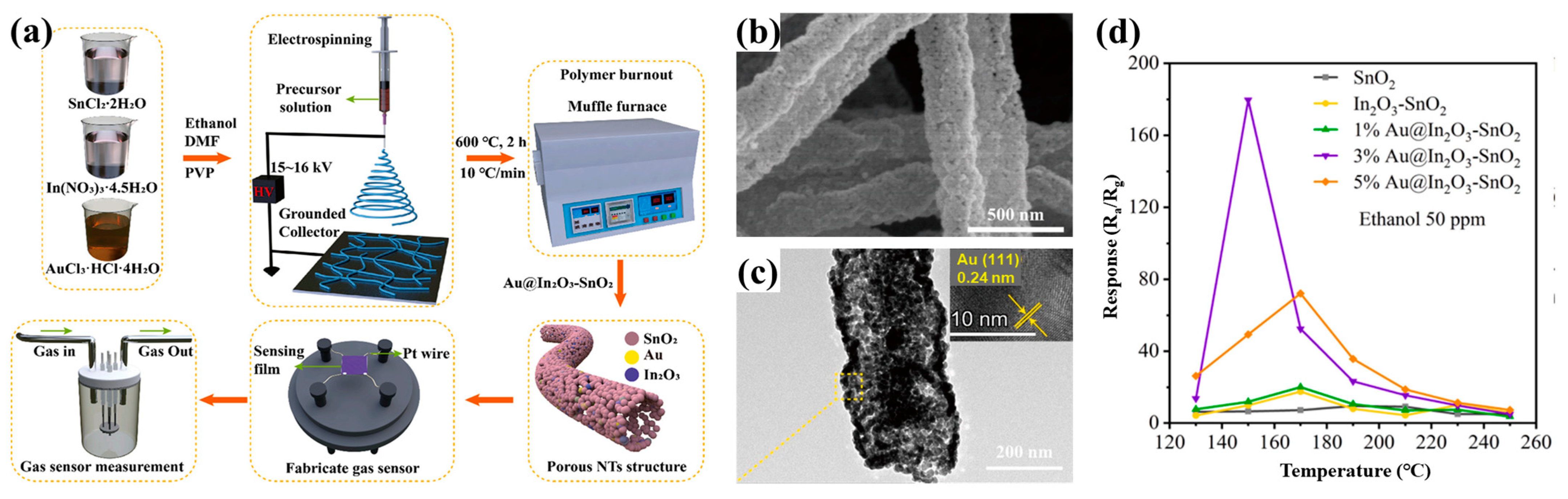
- Chen, L.; Shi, H.; Ye, C.; Xia, X.; Li, Y.; Pan, C.; Song, Y.; Liu, J.; Dong, H.; Wang, D.; et al. Enhanced ethanol-sensing characteristics of Au decorated In-doped SnO2 porous nanotubes at low working temperature. Sens. Actuat. B-Chem. 2023, 375, 132864. [Google Scholar] [CrossRef]
- Park, M.; Park, H.K.; Shin, H.K.; Kang, D.; Pant, B.; Kim, H.; Song, J.-K.; Kim, H.Y. Sound absorption and insulation properties of a polyurethane foam mixed with electrospun nylon-6 and polyurethane nanofibre mats. J. Nanosci. Nanotechnol. 2019, 19, 3558–3563. [Google Scholar] [CrossRef] [PubMed]
- Cho, Y.S.; Lee, H.J. Fabrication of porous silica fibers by electrospinning for sound absorbing materials. Arch. Metall. Mater. 2018, 63, 1497–1502. [Google Scholar]
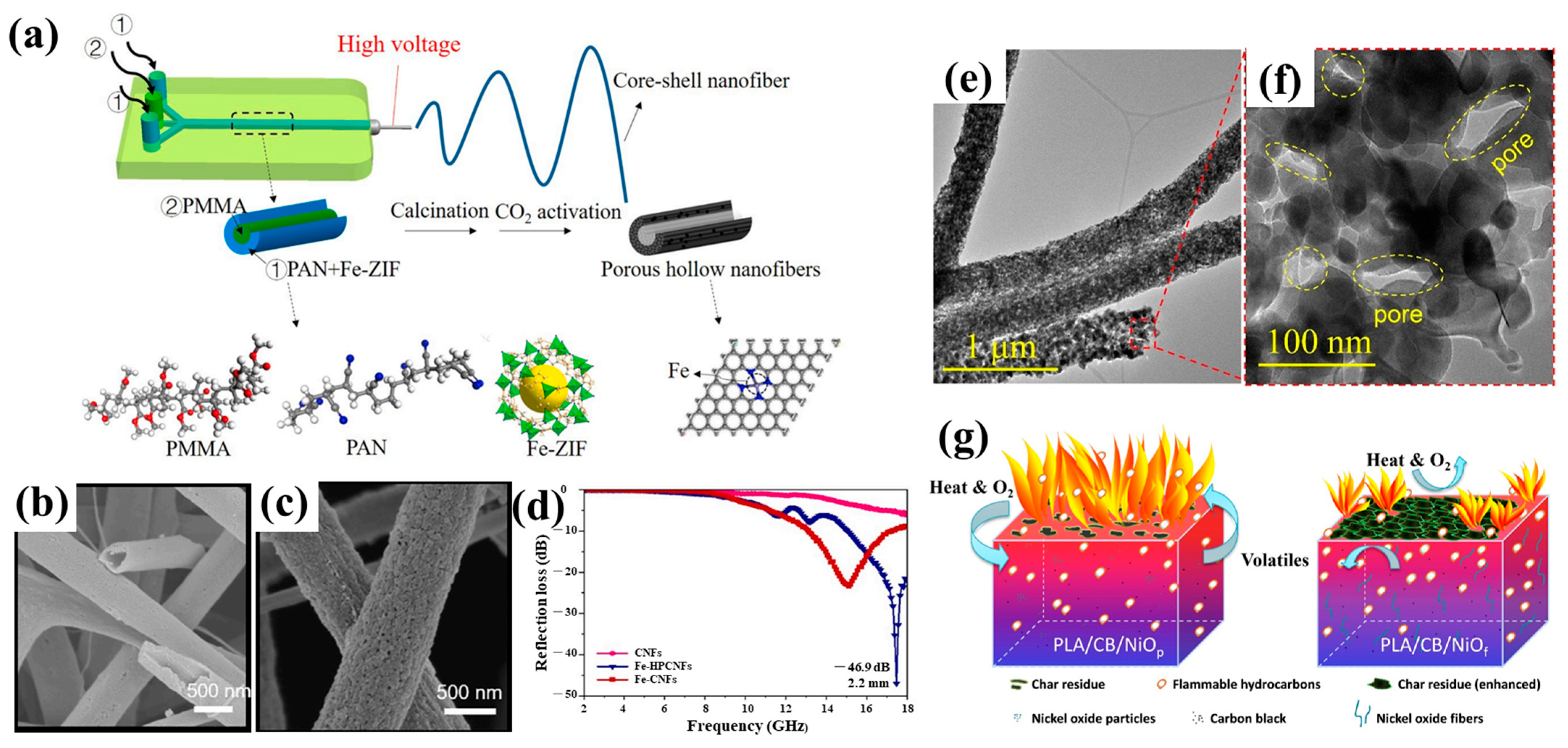
- Ruiling, S.; Guilong, Y.; Xunlong, Z.; Zhenyu, L.; Jingyu, C.; Li, W.; Yuanpeng, W.; Yiqun, W.; Han, L. Fe-ZIF-derived hollow porous carbon nanofibers for electromagnetic wave absorption. Chem. Eng. J. 2022, 455, 140608. [Google Scholar]
- Cui, Y.; Gong, H.; Wang, Y.; Li, D.; Bai, H. A thermally insulating textile inspired by polar bear hair. Adv. Mater. 2018, 30, 1706807. [Google Scholar] [CrossRef] [PubMed]
- Wang, Y.; Huang, H.; Zhao, Y.; Feng, Z.; Fan, H.; Sun, T.; Xu, Y. Self-assembly of ultralight and compressible inorganic sponges with hierarchical porosity by electrospinning. Ceram. Int. 2020, 46, 768–774. [Google Scholar] [CrossRef]
- Zhang, L.; Liu, W.; Wen, X.; Chen, J.; Zhao, C.; Castillo-Rodríguez, M.; Yang, L.; Zhang, X.-Q.; Wang, R.; Wang, D.-Y. Electrospun submicron NiO fibers combined with nanosized carbon black as reinforcement for multi-functional poly(lactic acid) composites. Compos. Part A-Appl. Sci. Manuf. 2020, 129, 105662. [Google Scholar] [CrossRef]
- Wang, M.-L.; Yu, D.-G.; Annie Bligh, S.W. Progress in preparing electrospun Janus fibers and their applications. Appl. Mater. Today 2023, 31, 101766. [Google Scholar] [CrossRef]
- Wang, M.; Ge, R.; Zhao, P.; Williams, G.R.; Yu, D.-G.; Annie Bligh, S.W. Exploring wettability difference-driven wetting by utilizing electrospun chimeric Janus microfiber comprising cellulose acetate and polyvinylpyrrolidone. Mater. Des. 2023, 226, 111652. [Google Scholar] [CrossRef]
- Song, W.; Tang, Y.; Qian, C.; Kim, B.J.; Liao, Y.; Yu, D.G. Electrospinning spinneret: A bridge between the visible world and the invisible nanostructures. The Innovation 2023, 4, 100381. [Google Scholar] [CrossRef]
- Xie, D.; Zhou, X.; Xiao, B.; Duan, L.; Zhu, Z. Mucus-Penetrating Silk Fibroin-Based Nanotherapeutics for Efficient Treatment of Ulcerative Colitis. Biomolecules 2022, 12, 1263. [Google Scholar] [CrossRef] [PubMed]
- Shen, Y.H.; Yu, X.; Cui, J.; Yu, F.; Liu, M.Y.; Chen, Y.J.; Wu, J.L.; Sun, B.B.; Mo, X.M. Development of Biodegradable Polymeric Stents for the Treatment of Cardiovascular Diseases. Biomolecules 2022, 12, 1245. [Google Scholar] [CrossRef] [PubMed]
- Yao, L.; Sun, C.; Lin, H.; Li, G.; Lian, Z.; Song, R.; Zhuang, S.; Zhang, D. Electrospun Bi-Decorated BixTiyOz/TiO2 Flexible Carbon Nanofibers and Their Applications on Degradating of Organic Pollutants Under Solar Radiation. J. Mater. Sci. Technol. 2023. [Google Scholar] [CrossRef]
- Meng, Y.; Chen, L.; Chen, Y.; Shi, J.; Zhang, Z.; Wang, Y.; Wu, F.; Jiang, X.; Yang, W.; Zhang, L.; et al. Reactive Metal Boride Nanoparticles Trap Lipopolysaccharide and Peptidoglycan for Bacteria-Infected Wound Healing. Nat. Commun. 2022, 13, 7353. [Google Scholar] [CrossRef] [PubMed]
- Xu, J.; Zhong, M.; Song, N.; Wang, C.; Lu, X. General Synthesis of Pt and Ni Co-Doped Porous Carbon Nanofibers to Boost HER Performance in Both Acidic and Alkaline Solutions. Chin. Chem. Lett. 2023, 34, 107359. [Google Scholar] [CrossRef]
- Huang, J.; Feng, C. Aniline Dimers Serving as Stable and Efficient Transfer Units for Intermolecular Charge-Carrier Transmission. iscience 2023, 26, 105762. [Google Scholar] [CrossRef]
- Wang, X.; Feng, C. Chiral Fiber Supramolecular Hydrogels for Tissue Engineering. Wiley Interdiscip. Rev.-Nanomed. NanoBiotechnol. 2022, 14, e1847. [Google Scholar] [CrossRef]
- Li, C.; Wang, J.; Deng, C.; Wang, R.; Zhang, H. Protocol for Atmospheric Water Harvesting Using in situ Polymerization Honeycomb Hygroscopic Polymers. STAR Protoc. 2022, 3, 101780. [Google Scholar] [CrossRef]
- Zhao, P.; Li, H.; Bu, W. A Forward Vision for Chemodynamic Therapy: Issues and Opportunities. Angew. Chem. Int. Ed. 2023, e202210415. [Google Scholar]
- Zhu, H.; Xing, C.; Dou, X.; Zhao, Y.; Peng, Y.; Feng, C.; Fang, Y. Chiral Hydrogel Accelerates Re-Epithelization in Chronic Wounds via Mechanoregulation. Adv. Healthc. Mater. 2022, 11, 2201032. [Google Scholar] [CrossRef] [PubMed]
- Huang, H.; Song, Y.; Zhang, Y.; Li, Y.; Li, J.; Lu, X.; Wang, C. Electrospun Nanofibers: Current Progress and Applications in Food Systems. J. Agric. Food Chem. 2022, 70, 1391–1409. [Google Scholar] [CrossRef] [PubMed]
- Wang, Q.; Liu, Q.; Gao, J.; He, J.; Zhang, H.; Ding, J. Stereo Coverage and Overall Stiffness of Biomaterial Arrays Underly Parts of Topography Effects on Cell Adhesion. ACS Appl. Mater. Interf. 2023, 15, 6142–6155. [Google Scholar] [CrossRef] [PubMed]
- Chen, L.; Jiang, X.; Lv, M.; Wang, X.; Zhao, P.; Zhang, M.; Lv, G.; Wu, J.; Liu, Y.; Yang, Y.; et al. Reductive-Damage-Induced Intracellular Maladaptation for Cancer Electronic Interference Therapy. Chem 2022, 8, 866–879. [Google Scholar] [CrossRef]
- Chen, W.; Zhao, P.; Yang, Y.; Yu, D.G. Electrospun Beads-on-the-string Nanoproducts: Preparation and Drug Delivery Application. Curr. Drug Deliv. 2022, 19. [Google Scholar] [CrossRef]
- Wu, Y.; Li, Y.; Lv, G.; Bu, W. Redox Dyshomeostasis Strategy for Tumor Therapy Based on Nanomaterials Chemistry. Chem. Sci. 2022, 13, 2202–2217. [Google Scholar] [CrossRef]
- Lu, H.; Zhao, Y.; Qin, S.; Zhang, Y.; Liu, J.; Zhang, J.; Feng, C.; Zhao, W. Fluorine Substitution Tunes the Nanofiber Chirality of Supramolecular Hydrogels to Promote Cell Adhesion and Proliferation. Adv. Fiber Mater. 2023, 5, 377–387. [Google Scholar] [CrossRef]
- Tang, Z.; Wu, S.; Zhao, P.; Wang, H.; Ni, D.; Li, H.; Jiang, X.; Wu, Y.; Meng, Y.; Yao, Z.; et al. Chemical Factory-Guaranteed Enhanced Chemodynamic Therapy for Orthotopic Liver Cancer. Adv. Sci. 2022, 9, 2201232. [Google Scholar] [CrossRef]


| Type | Mechanism | Polymer | Solvent | Humidity | Pore Structure | Pore Size (nm) | Porosity | Ref. |
|---|---|---|---|---|---|---|---|---|
| VIPS | Water molecules are mixed with a low-volatile solvent, resulting in phase separation. | Hydrophobic polymer | Single, low-volatile, miscible with water | High | Surface and internal, elliptical | Large, 50–300 | Reached 92% | [118,119] |
| TIPS | Significant temperature difference between fibers and the surrounding environment results in phase separation. | Not required | Single, low-volatile | Not required | Surface | Small, 2–50 | Lower than other pore-forming mechanisms | [113,120] |
| NIPS | Volatility difference between the solvent and nonsolvent results in phase separation. | Not required | High-volatile solvent and low-volatile nonsolvent | Not required | Surface and internal, elliptical | Small, 20–100 | Less than 80% | [55,121] |
Disclaimer/Publisher’s Note: The statements, opinions and data contained in all publications are solely those of the individual author(s) and contributor(s) and not of MDPI and/or the editor(s). MDPI and/or the editor(s) disclaim responsibility for any injury to people or property resulting from any ideas, methods, instructions or products referred to in the content. |
© 2023 by the authors. Licensee MDPI, Basel, Switzerland. This article is an open access article distributed under the terms and conditions of the Creative Commons Attribution (CC BY) license (https://creativecommons.org/licenses/by/4.0/).
Share and Cite
Wang, P.; Lv, H.; Cao, X.; Liu, Y.; Yu, D.-G. Recent Progress of the Preparation and Application of Electrospun Porous Nanofibers. Polymers 2023, 15, 921. https://doi.org/10.3390/polym15040921
Wang P, Lv H, Cao X, Liu Y, Yu D-G. Recent Progress of the Preparation and Application of Electrospun Porous Nanofibers. Polymers. 2023; 15(4):921. https://doi.org/10.3390/polym15040921
Chicago/Turabian StyleWang, Pu, He Lv, Xianyang Cao, Yanan Liu, and Deng-Guang Yu. 2023. "Recent Progress of the Preparation and Application of Electrospun Porous Nanofibers" Polymers 15, no. 4: 921. https://doi.org/10.3390/polym15040921
APA StyleWang, P., Lv, H., Cao, X., Liu, Y., & Yu, D.-G. (2023). Recent Progress of the Preparation and Application of Electrospun Porous Nanofibers. Polymers, 15(4), 921. https://doi.org/10.3390/polym15040921