
Evaluating the Electromagnetic Shielding of Continuous Carbon Fiber Parts Produced by Additive Manufacturing

 ,
,
Abstract
:1. Introduction
2. Materials and Methods
2.1. Materials
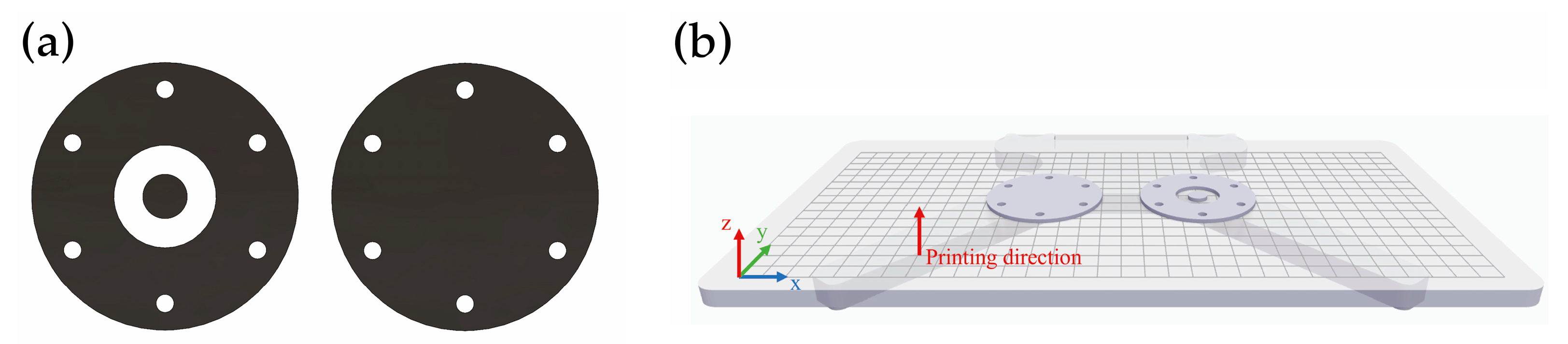
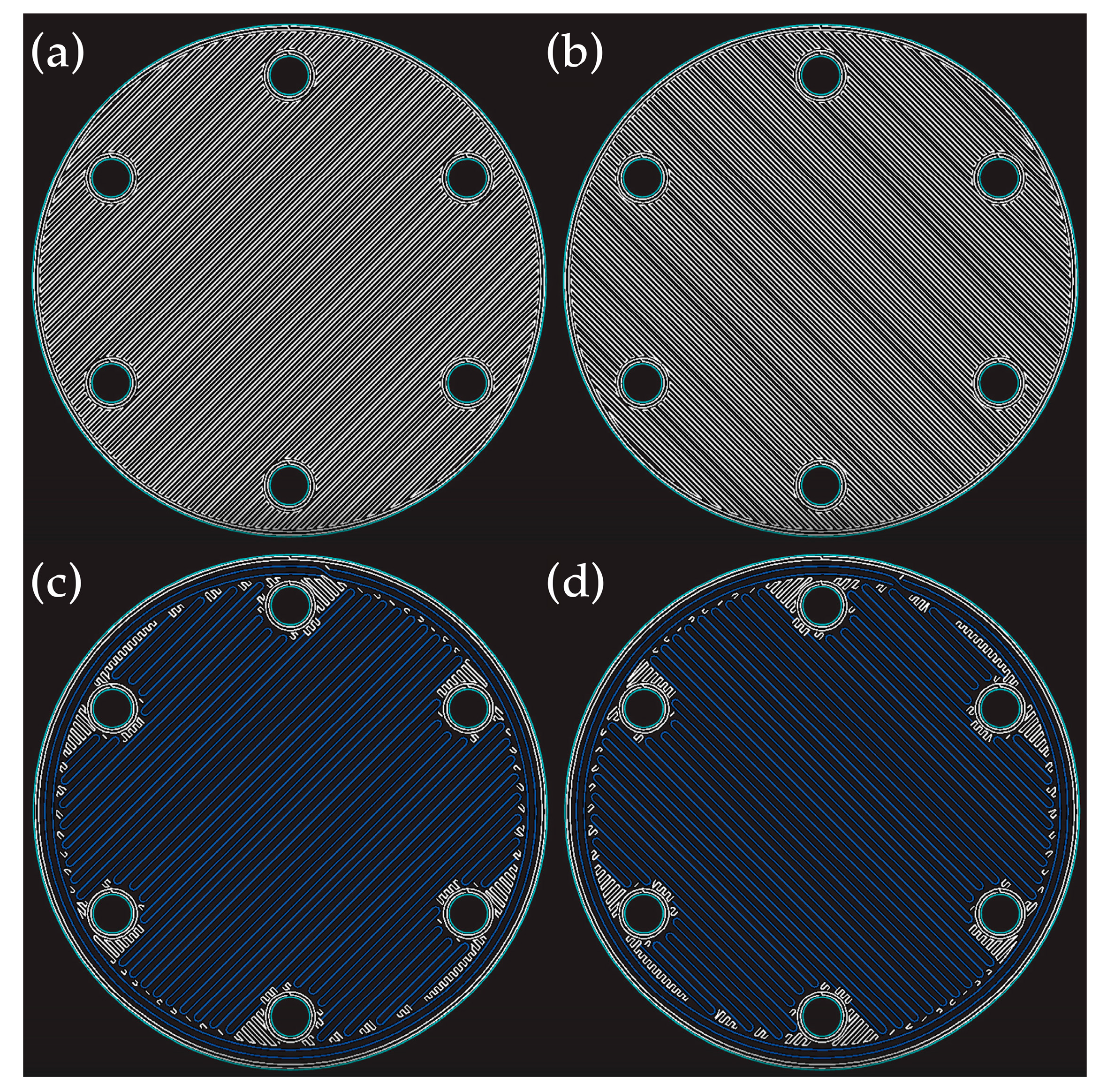
2.2. Production
2.3. Characterization
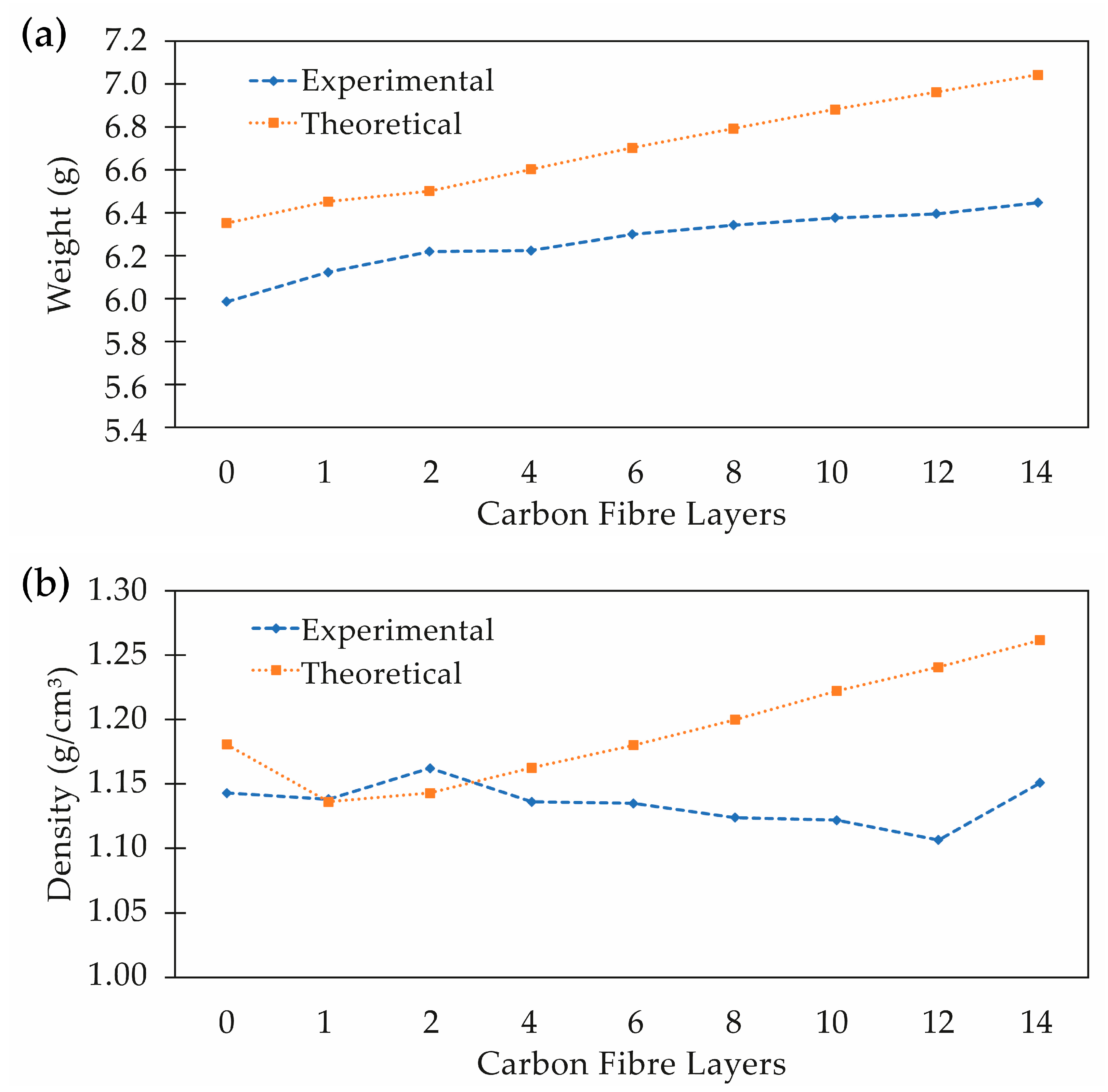
2.3.1. Thickness, Weight and Density
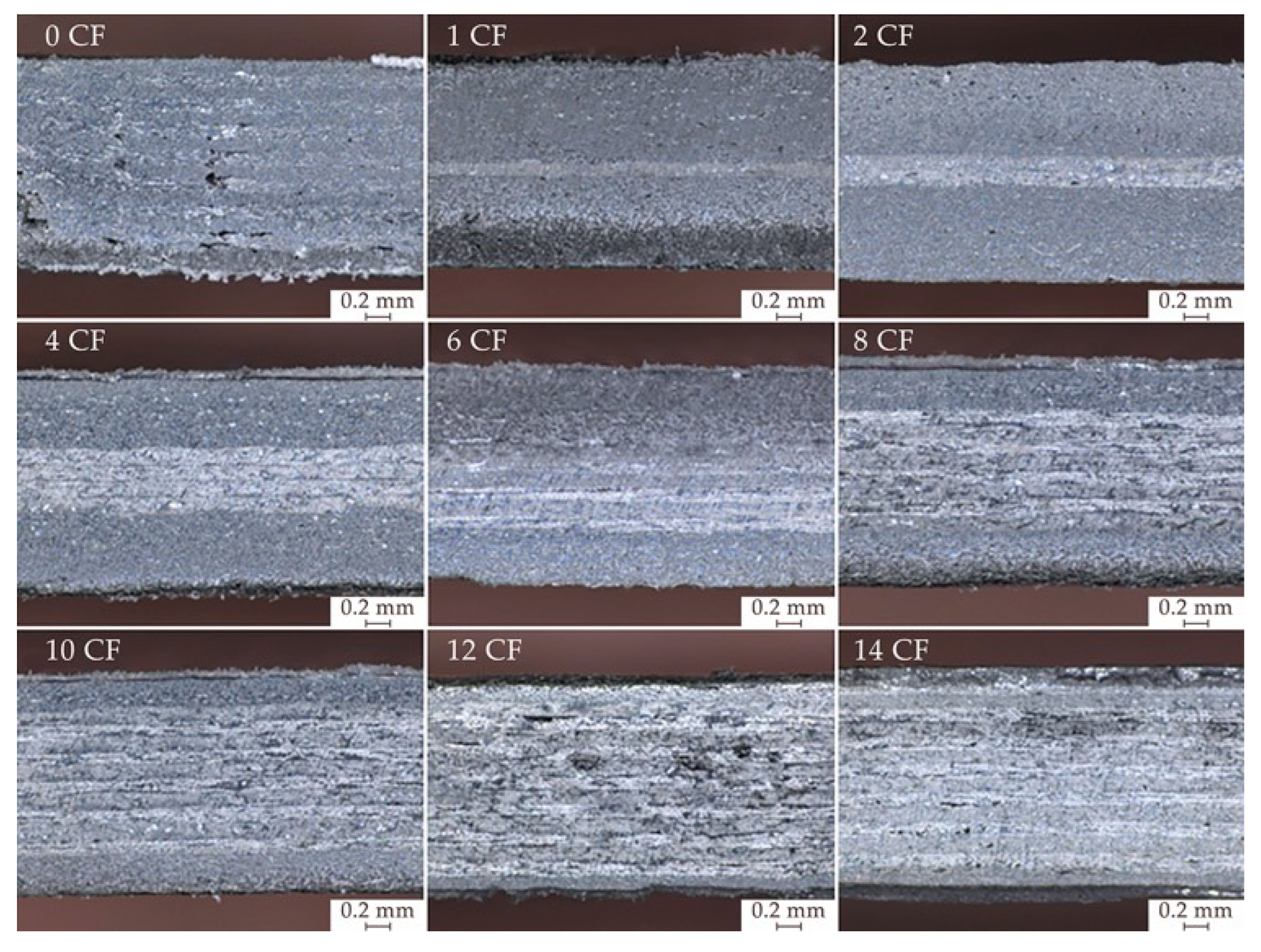
2.3.2. Morphology
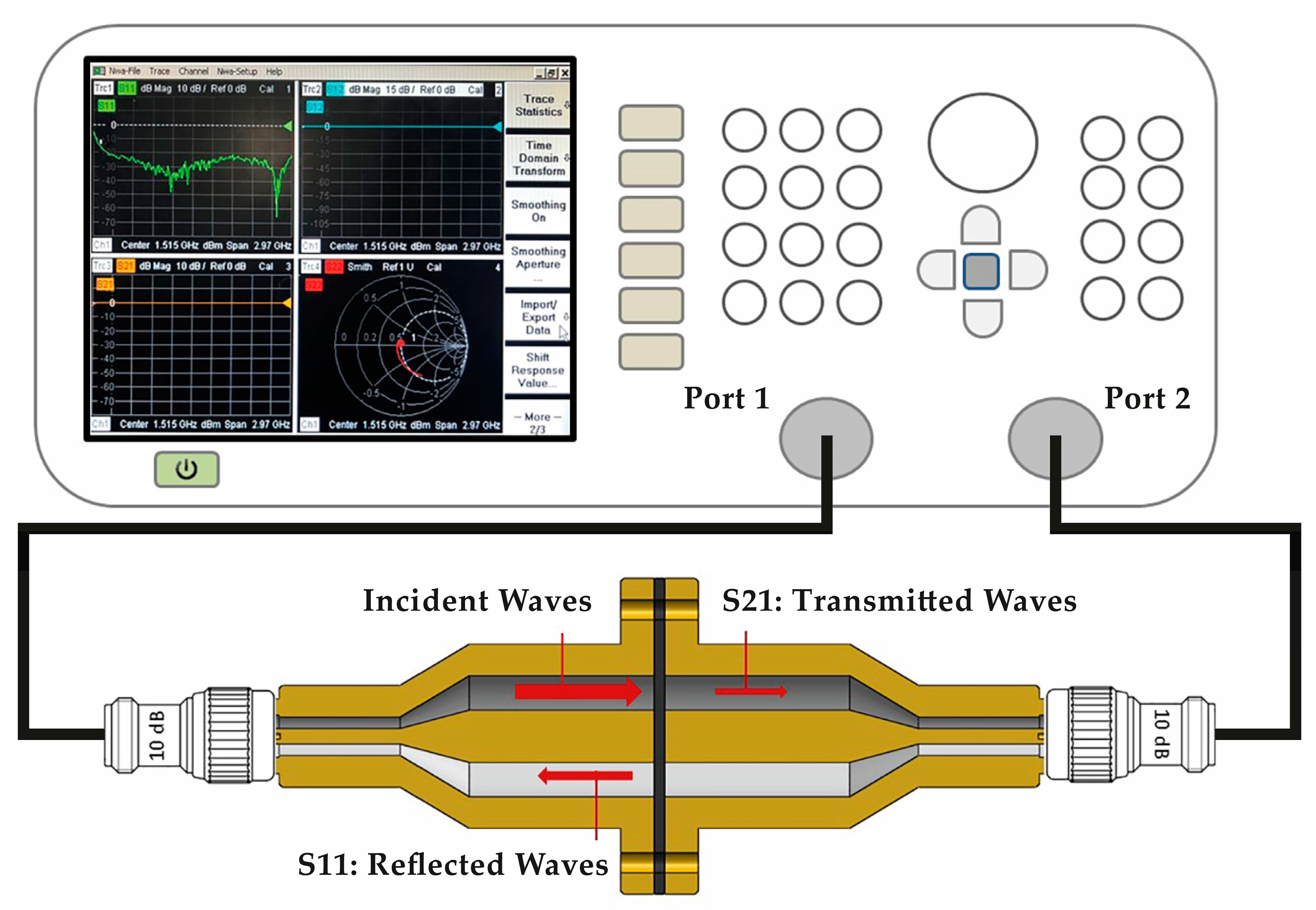
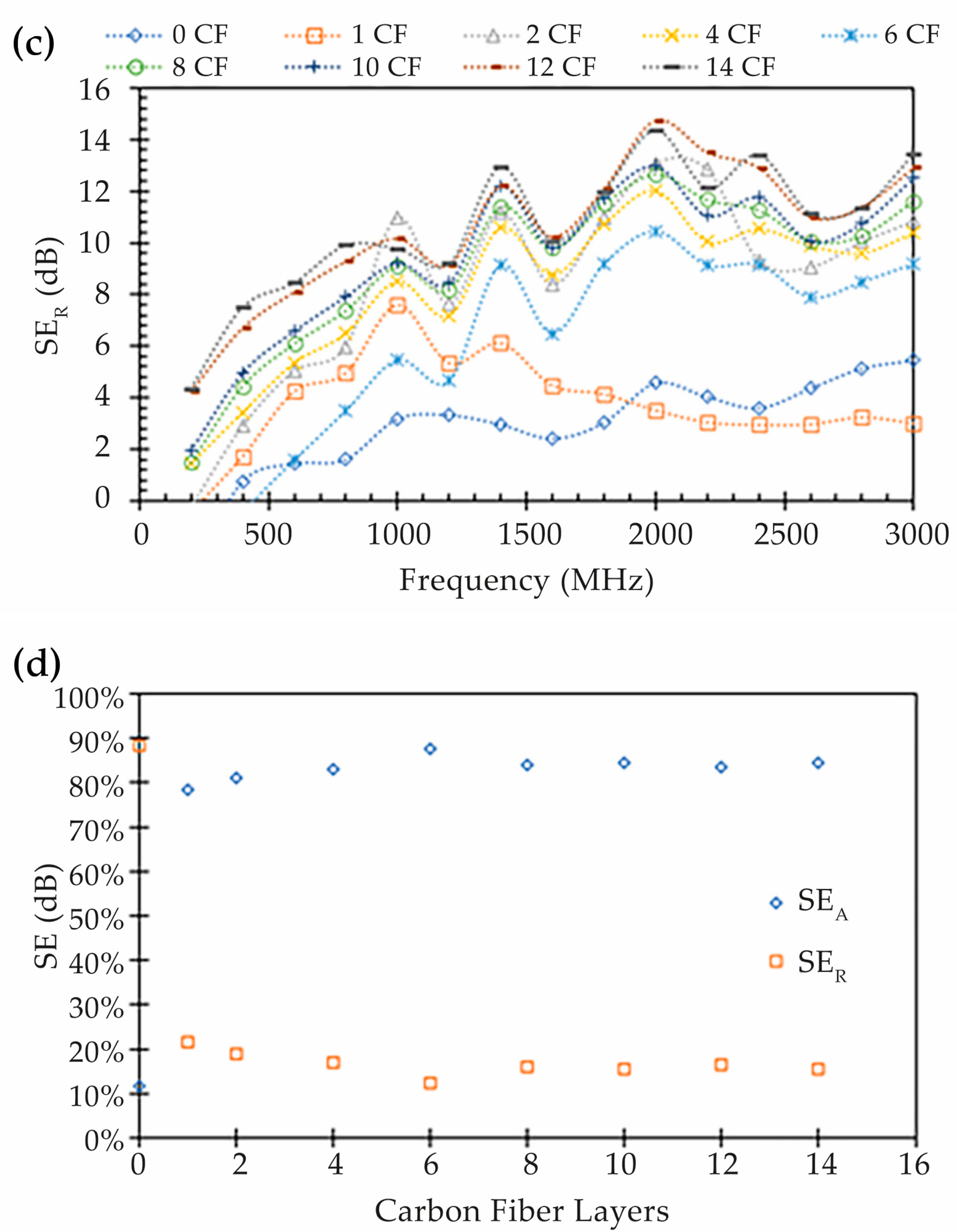
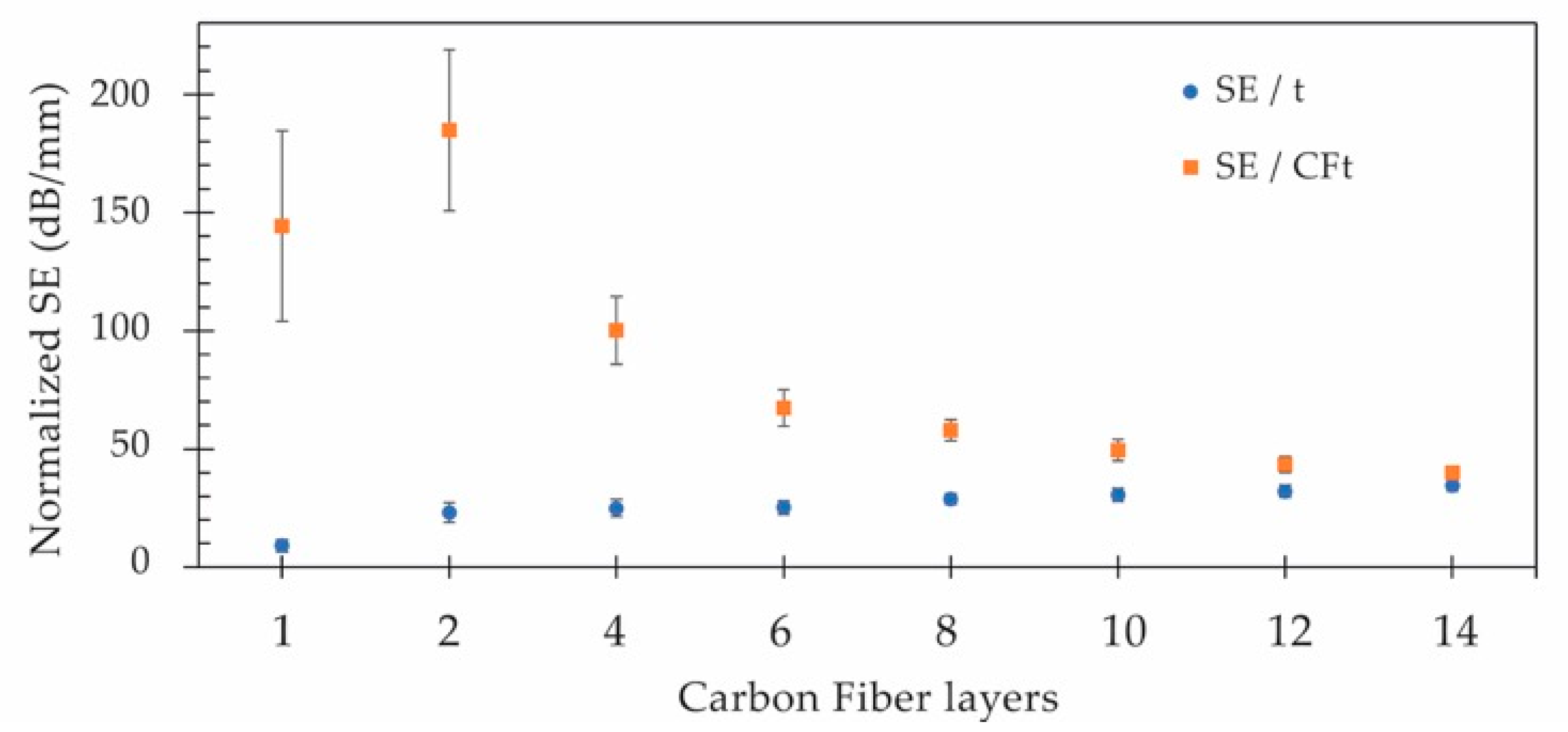
2.3.3. Electromagnetic Shielding Effectiveness
2.3.4. Electrical Conductivity
3. Results and Discussion
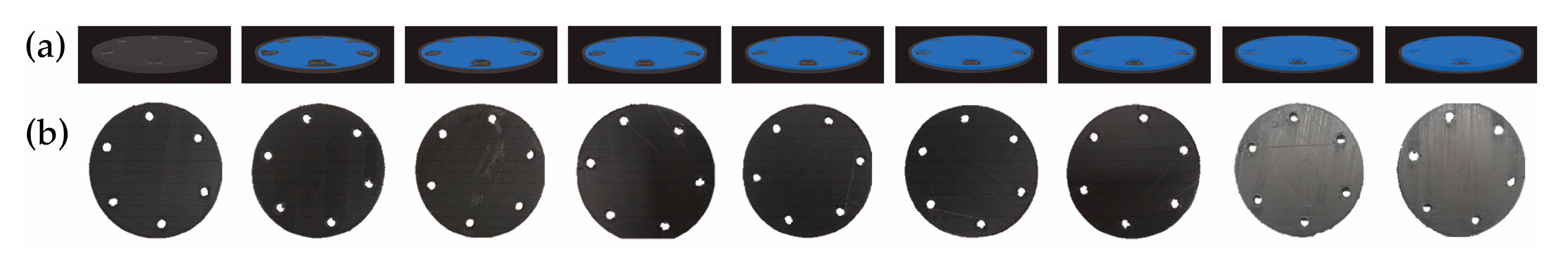
3.1. Quality of the Printed Composite Specimens
3.2. Electromagnetic Shielding
4. Conclusions
Author Contributions
Funding
Institutional Review Board Statement
Data Availability Statement
Conflicts of Interest
References
- Chikyu, N.; Nakano, T.; Kletetschka, G.; Inoue, Y. Excellent electromagnetic interference shielding characteristics of a unidirectionally oriented thin multiwalled carbon nanotube/polyethylene film. Mater. Des. 2020, 195, 108918. [Google Scholar] [CrossRef]
- Kaiser, K.L. Electromagnetic Shielding, 1st ed.; CRC Press: Boca Raton, FL, USA, 2005. [Google Scholar]
- Tong, X.C. Advanced Materials and Design for Electromagnetic Interference Shielding, 1st ed.; CRC Press: Boca Raton, FL, USA, 2009. [Google Scholar]
- Chung, D.D.L. Materials for Electromagnetic Interference Shielding. J. Mater. Eng. Perform. 2000, 9, 350–354. [Google Scholar] [CrossRef]
- Aciu, L.E.V.; Ogrutan, P.L.P.; Badic, M.V. New Methods Developed for Shielding Materials Characterization. Annals of the University of Craiova, Electrical Engineering Series. 2009. Available online: https://elth.ucv.ro/fisiere/anale/2009/1.pdf (accessed on 30 September 2023).
- Geetha, S.; Kumar, K.K.S.; Rao, C.R.K.; Vijayan, M.; Trivedi, D.C. EMI Shielding: Methods and Materials—A Review. J. Appl. Polym. Sci. 2009, 112, 2073–2086. [Google Scholar] [CrossRef]
- Bryant, N. Using Long Fiber Nickel Coated Carbon Fiber (LFNCCF) to produce Light Weight EMI Shielding Plastic Composites. In Proceedings of the 2013 IEEE International Symposium on Electromagnetic Compatibility, Denver, CO, USA, 5–9 August 2013; pp. 371–375. [Google Scholar]
- Morari, C.; Balan, I.; Pintea, J.; Elena, C.; Iordache, I. Electrical Conductivity and Electromagnetic Shielding Effectiveness of Silicone Rubber Filled with Ferrite and Graphite Powders. Prog. Electromagn. Res. M 2011, 21, 93–104. [Google Scholar] [CrossRef]
- Al-Saleh, M.H.; Sundararaj, U. Electromagnetic interference shielding mechanisms of CNT / polymer composites. Carbon 2009, 47, 1738–1746. [Google Scholar] [CrossRef]
- Fan, J.; Zhang, L.; Wei, S.; Zhang, Z.; Choi, S.-K.; Song, B.; Shi, Y. A review of additive manufacturing of metamaterials and developing trends. Mater. Today 2021, 50, 303–328. [Google Scholar] [CrossRef]
- Yuan, S.; Li, S.; Zhu, J.; Tang, W. Additive manufacturing of polymeric composites from material processing to structural design. Compos. Part B Eng. 2021, 219, 108903. [Google Scholar] [CrossRef]
- Saini, P.; Arora, M. Microwave Absorption and EMI Shielding Behavior of Nanocomposites Based on Intrinsically Conducting Polymers, Graphene and Carbon Nanotubes. In New Polymers for Special Applications, 1st ed.; Gomes, A.D.S., Ed.; IntechOpen: London, UK, 2012; pp. 71–112. [Google Scholar]
- Jiang, D.; Murugadoss, V.; Wang, Y.; Lin, J.; Ding, T.; Wang, Z.; Shao, Q.; Whang, C.; Liu, H.; Wei, R.; et al. Electromagnetic Interference Shielding Polymers and Nanocomposites—A Review. Polym. Rev. 2019, 59, 280–337. [Google Scholar] [CrossRef]
- Das, T.K.; Prusty, S. Review on Conducting Polymers and Their Applications. Polym. Plast. Technol. Eng. 2012, 51, 1487–1500. [Google Scholar] [CrossRef]
- Martins, L.C.; Pontes, A.J. Fiber reinforced thermoplastics compounds for electromagnetic interference shielding applications. J. Reinf. Plast. Compos. 2021, 41, 206–214. [Google Scholar] [CrossRef]
- Chiu, S.K.; Cheng, J.Y.; Jou, W.S.; Jong, G.-J.; Wang, S.C.; Wang, C.M.; Lin, C.S.; Wu, T.L.; Cheng, W.H. Electromagnetic shielding of plastic material in laser diode modules. In Proceedings of the 2001 51st Electronic Components and Technology Conference (Cat. No.01CH37220), Orlando, FL, USA, 29 May–1 June 2001; pp. 645–647. [Google Scholar]
- Thomassin, J.M.; Jérôme, C.; Pardoen, T.; Bailly, C.; Huynen, I.; Detrembleur, C. Polymer/carbon based composites as electromagnetic interference (EMI) shielding materials. Mater. Sci. Eng. R Rep. 2013, 74, 211–232. [Google Scholar] [CrossRef]
- Chung, D.D. Electromagnetic interference shielding effectiveness of carbon materials. Carbon 2001, 39, 279–285. [Google Scholar] [CrossRef]
- Sankaran, S.; Deshmukh, K.; Ahamed, M.B.; Pasha, S.K.K. Recent advances in electromagnetic interference shielding properties of metal and carbon filler reinforced flexible polymer composites: A review. Compos. Part A Appl. Sci. Manuf. 2018, 114, 49–71. [Google Scholar] [CrossRef]
- Al-Saleh, M.H.; Sundararaj, U. Electromagnetic interference (EMI) shielding effectiveness of PP/PS polymer blends containing high structure carbon black. Macromol. Mater. Eng. 2008, 293, 621–630. [Google Scholar] [CrossRef]
- Oliveira, F.M.; Azadmanjiri, J.; Wang, X.; Yu, M.; Sofer, Z. Structure Design and Processing Strategies of MXene-Based Materials for Electromagnetic Interference Shielding. Small Methods 2023, 7, 2300112. [Google Scholar] [CrossRef]
- Namvari, M.; Inan, T.; Altan, A. MXene-cellulose nanofber composites: Toward green, multi-functional, fexible, and highly efcient electromagnetic interference shielding materials. Graphene 2D Mater. 2023, 8, 5–26. [Google Scholar] [CrossRef]
- Ameli, A.; Jung, P.U.; Park, C.B. Low Percolation Threshold and Improved Electromagnetic Interference Shielding Effectiveness Polypropylene/Carbon Fiber Composites Through Foaming. In Proceedings of the Society of Plastics Engineering SPE-ANTEC 2013, Cincinnati, OH, USA, 22–24 April 2013; pp. 6–11. [Google Scholar]
- Mahmoodi, M.; Arjmand, M.; Sundararaj, U.; Park, S. The electrical conductivity and electromagnetic interference shielding of injection molded multi-walled carbon nanotube/polystyrene composites. Carbon 2012, 50, 1455–1464. [Google Scholar] [CrossRef]
- Arjmand, M.; Mahmoodi, M.; Gelves, G.A.; Park, S.; Sundararaj, U. Electrical and electromagnetic interference shielding properties of flow-induced oriented carbon nanotubes in polycarbonate. Carbon 2011, 49, 3430–3440. [Google Scholar] [CrossRef]
- Arjmand, M.; Apperley, T.; Okoniewski, M.; Sundararaj, U. Comparative study of electromagnetic interference shielding properties of injection molded versus compression molded multi-walled carbon nanotube/polystyrene composites. Carbon 2012, 50, 5126–5134. [Google Scholar] [CrossRef]
- Al-saleh, M.H.; Sundararaj, U. Microstructure, Electrical, and Electromagnetic Interference Shielding Properties of Carbon Nanotube/Acrylonitrile—Butadiene—Styrene Nanocomposites. J. Polym. Sci. Part B Polym. Phys. 2012, 50, 1356–1362. [Google Scholar] [CrossRef]
- Chizari, K.; Arjmand, M.; Liu, Z.; Sundararaj, U.; Therriault, D. Three-dimensional printing of highly conductive polymer nanocomposites for EMI shielding applications. Mater. Today Commun. 2017, 11, 112–118. [Google Scholar] [CrossRef]
- Martins, L.C.; Barbosa, C.N.; Silva, S.; Bernardo, P.; Dias, G.R.; Pontes, A.J. Effect of processing conditions on electromagnetic shielding and electrical resistivity of injection-molded polybutylene terephthalate compounds. Polym. Eng. Sci. 2021, 6, 2576–2588. [Google Scholar] [CrossRef]
- Wang, G.; Zhao, G.; Wang, S.; Zhang, L.; Park, C.B. Injection-molded microcellular PLA/graphite nanocomposites with dramatically enhanced mechanical and electrical properties for ultra-efficient EMI shielding applications. J. Mater. Chem. C 2018, 6, 6847–6859. [Google Scholar] [CrossRef]
- Zhang, Y.; Wang, Z.; Zhang, Y.; Gomes, S.; Bernard, A. Bio-inspired generative design for support structure generation and optimization in Additive Manufacturing (AM). CIRP Ann. 2020, 69, 117–120. [Google Scholar] [CrossRef]
- Hoang, V.N.; Nguyen, N.L.; Tran, P.; Qjan, M.; Nguyen-Xuan, J. Adaptive Concurrent Topology Optimization of Cellular Composites for Additive Manufacturing. JOM 2020, 72, 2378–2390. [Google Scholar] [CrossRef]
- Nath, S.D.; Nilufar, S. An overview of additive manufacturing of polymers and associated composites. Polymers 2020, 12, 2719. [Google Scholar] [CrossRef]
- Redwood, B.; Schöffer, F.; Garret, B. The 3D Printing Handbook: Technologies, Design and Applications, 1st ed.; 3D Hubs: Amsterdam, The Netherlands, 2017; pp. 27–51. [Google Scholar]
- Ngo, T.D.; Kashani, A.; Imbalzano, G.; Nguyen, K.T.Q.; Hui, D. Additive manufacturing (3D printing): A review of materials, methods, applications and challenges. Compos. Part B Eng. 2018, 143, 172–196. [Google Scholar] [CrossRef]
- Motaparti, K.P. Effect of Build Parameters on Mechanical Properties of Ultem 9085 Parts by Fused Deposition Modeling. Master Thesis, Missouri University of Science and Technology, Rolla, MO, USA, 2016. [Google Scholar]
- Ferreira, R.T.L.; Amatte, I.C.; Dutra, T.A.; Bürger, D. Experimental characterization and micrography of 3D printed PLA and PLA reinforced with short carbon fibers. Compos. Part. B Eng. 2017, 124, 88–100. [Google Scholar] [CrossRef]
- Dorigato, A.; Moretti, V.; Dul, S.; Unterberger, S.H.; Pegoretti, A. Electrically conductive nanocomposites for fused deposition modelling. Synth. Met. 2017, 226, 7–14. [Google Scholar] [CrossRef]
- Schmitz, D.P.; Ecco, L.G.; Dul, S.; Pereira, E.C.L.; Soares, B.G.; Barra, G.M.O.; Pegoretti, A. Electromagnetic interference shielding effectiveness of ABS carbon-based composites manufactured via fused deposition modelling. Mater. Today Commun. 2018, 15, 70–80. [Google Scholar] [CrossRef]
- Mohan, V.B.; Krebs, B.J.; Bhattacharyya, D. Development of novel highly conductive 3D printable hybrid polymer-graphene composites. Mater. Today Commun. 2018, 17, 554–561. [Google Scholar] [CrossRef]
- Li, Y.; Feng, Z.; Huang, L.; Essa, K.; Bilotti, E.; Zhang, H.; Peijs, T.; Hao, L. Additive manufacturing high performance graphene-based composites: A review. Compos. Part A Appl. Sci. Manuf. 2019, 124, 105483. [Google Scholar] [CrossRef]
- Hohimer, C.J.; Petrossian, G.; Ameli, A.; Mo, C.; Pötschke, P. 3D printed conductive thermoplastic polyurethane/carbon nanotube composites for capacitive and piezoresistive sensing in soft pneumatic actuators. Addit. Manuf. 2020, 34, 101281. [Google Scholar] [CrossRef]
- Schmitz, D.P.; Dul, S.; Ramoa, S.D.A.S.; Soares, B.G.; Barra, G.M.O.; Pegoretti, A. Effect of printing parameters on the electromagnetic shielding efficiency of ABS/carbonaceous-filler composites manufactured via filament fused fabrication. J. Manuf. Process 2021, 65, 12–19. [Google Scholar] [CrossRef]
- Lee, K.P.M.; Baum, T.; Shanks, R.; Daver, F. Electromagnetic interference shielding of 3D-printed graphene–polyamide-6 composites with 3D-printed morphology. Addit. Manuf. 2021, 43, 102020. [Google Scholar] [CrossRef]
- Wang, Y.; Fan, Z.W.; Zhang, H.; Guo, J.; Yan, D.-X.; Wang, S.; Dai, K.; Li, Z.-M. 3D-printing of segregated carbon nanotube/polylactic acid composite with enhanced electromagnetic interference shielding and mechanical performance. Mater. Des. 2021, 197, 109222. [Google Scholar] [CrossRef]
- Duan, Y.; Liang, Q.; Yang, Z.; Li, Z.; Yin, H.; Cao, Y.; Li, D. A wide-angle broadband electromagnetic absorbing metastructure using 3D printing technology. Mater. Des. 2021, 208, 109900. [Google Scholar] [CrossRef]
- Parmiggiani, A.; Prato, M.; Pizzorni, M. Effect of the fiber orientation on the tensile and flexural behavior of continuous carbon fiber composites made via fused filament fabrication. Int. J. Adv. Manuf. Technol. 2021, 114, 2085–2101. [Google Scholar] [CrossRef]
- Blok, L.G.; Longana, M.L.; Yu, H.; Woods, B.K.S. An investigation into 3D printing of fibre reinforced thermoplastic composites. Addit. Manuf. 2018, 22, 176–186. [Google Scholar] [CrossRef]
- Markforged Material Datasheet Composites 2022. p. 2. Available online: https://www-objects.markforged.com/craft/materials/CompositesV5.2.pdf (accessed on 30 September 2023).
- ASTM D 4935-99; Standard Test Method for Measuring the Electromagnetic Shielding Effectiveness of Planar Materials. ASTM International: West Conshohocken, PA, USA, 1999.
- Hong, Y.K.; Lee, C.Y.; Jeong, C.K.; Lee, D.E.; Kim, K.; Joo, J. Method and apparatus to measure electromagnetic interference shielding efficiency and its shielding characteristics in broadband frequency ranges. Rev. Sci. Instrum. 2003, 74, 1098–1102. [Google Scholar] [CrossRef]
- Sarto, M.S.; Tamburrano, A. Innovative test method for the shielding effectiveness measurement of conductive thin films in a wide frequency range. IEEE Trans. Electromagn. Compat. 2006, 48, 331–341. [Google Scholar] [CrossRef]
- Vasquez, H.; Espinoza, L.; Lozano, K.; Foltz, H.; Yang, S. Simple Device for Electromagnetic Interference Shielding Effectiveness Measurement. IEEE Trans. Electromagn. Compat. 2009, 220, 62–68. [Google Scholar]
- Andersen, P. International electrotechnical commission documents CISPR 12 and CISPR 25—An overview. In Proceedings of the 2007 IEEE International Symposium on Electromagnetic Compatibility, Honolulu, HI, USA, 9–13 July 2007; pp. 1–4. [Google Scholar]
- Oliveira, F.M.; Martins, L.; Dencheva, N.V.; Ezquerra, T.A.; Denched, Z.Z. Tunable Electromagnetic Interference Shielding Properties of Binary Thermoplastic Composites Prepared by Reactive Microencapsulation. ACS Appl. Polym. Mater. 2022, 4, 3482–3490. [Google Scholar] [CrossRef]
- Ren, F.; Li, Z.; Xu, L.; Sun, Z.; Ren, P.; Yan, D.; Li, Z. Large-scale preparation of segregated PLA/carbon nanotube composite with high efficient electromagnetic interference shielding and favourable mechanical properties. Compos. Part B Eng. 2018, 155, 405–413. [Google Scholar] [CrossRef]
- Kong, W.; Yi, S.; Sun, W.; Xu, L.; Jia, L.; Yan, D.; Li, Z. Polyaniline-decorated carbon fibers for enhanced mechanical and electromagnetic interference shielding performances of epoxy composites. Mater. Des. 2022, 217, 110658. [Google Scholar] [CrossRef]
- ASTM D257; Standard Test Methods for DC Resistance or Conductance of Insulating Materials. ASTM International: West Conshohocken, PA, USA, 2021.
- Cui, C.H.; Yan, D.X.; Pang, H.; Jia, L.-C.; Xu, X.; Yang, S.; Xu, J.Z.; Li, Z.-M. A high heat-resistance bioplastic foam with efficient electromagnetic interference shielding. Chem. Eng. J. 2017, 323, 29–36. [Google Scholar] [CrossRef]
- Song, P.; Liang, C.; Wang, L.; Qiu, H.; Gu, H.; Kong, J.; Gu, J. Obviously improved electromagnetic interference shielding performances for epoxy composites via constructing honeycomb structural reduced graphene oxide. Compos. Sci. Technol. 2019, 181, 107698. [Google Scholar] [CrossRef]
- Kashi, S.; Gupta, R.K.; Baum, T.; Kao, N.; Bhattacharya, S.N. Morphology, electromagnetic properties and electromagnetic interference shielding performance of poly lactide/graphene nanoplatelet nanocomposites. Mater. Des. 2016, 95, 119–126. [Google Scholar] [CrossRef]
- Gedler, G.; Antunes, M.; Velasco, J.I.; Ozisik, R. Enhanced electromagnetic interference shielding effectiveness of polycarbonate/graphene nanocomposites foamed via 1-step supercritical carbon dioxide process. Mater. Des. 2016, 90, 906–914. [Google Scholar] [CrossRef]


| Layers | Designation of Specimens (O—Onyx™; CF—Carbon Fiber) | ||||||||
|---|---|---|---|---|---|---|---|---|---|
| 0 CF | 1 CF | 2 CF | 4 CF | 6 CF | 8 CF | 10 CF | 12 CF | 14CF | |
| 16 | O 45° | O 45° | O 45° | O 45° | O 45° | O 45° | O 45° | O 45° | O 45° |
| 15 | O −45° | O −45° | O −45° | O −45° | O −45° | O −45° | O −45° | O −45° | CF −45° |
| 14 | O 45° | O 45° | O 45° | O 45° | O 45° | O 45° | O 45° | CF 45° | CF 45° |
| 13 | O −45° | O −45° | O −45° | O −45° | O −45° | O −45° | CF −45° | CF −45° | CF −45° |
| 12 | O 45° | O 45° | O 45° | O 45° | O 45° | CF 45° | CF 45° | CF 45° | CF 45° |
| 11 | O −45° | O −45° | O −45° | O −45° | CF −45° | CF −45° | CF −45° | CF −45° | CF −45° |
| 10 | O 45° | O 45° | O 45° | CF 45° | CF 45° | CF 45° | CF 45° | CF 45° | CF 45° |
| 9 | O −45° | CF −45° | CF −45° | CF −45° | CF −45° | CF −45° | CF −45° | CF −45° | CF −45° |
| 8 | O 45° | O 45° | CF 45° | CF 45° | CF 45° | CF 45° | CF 45° | CF 45° | CF 45° |
| 7 | O −45° | O −45° | O −45° | CF −45° | CF −45° | CF −45° | CF −45° | CF −45° | CF −45° |
| 6 | O 45° | O 45° | O 45° | O 45° | CF 45° | CF 45° | CF 45° | CF 45° | CF 45° |
| 5 | O −45° | O −45° | O −45° | O −45° | O −45° | CF −45° | CF −45° | CF −45° | CF −45° |
| 4 | O 45° | O 45° | O 45° | O 45° | O 45° | O 45° | CF 45° | CF 45° | CF 45° |
| 3 | O −45° | O −45° | O −45° | O −45° | O −45° | O −45° | O −45° | CF −45° | CF −45° |
| 2 | O 45° | O 45° | O 45° | O 45° | O 45° | O 45° | O 45° | O 45° | CF 45° |
| 1 | O −45° | O −45° | O −45° | O −45° | O −45° | O −45° | O −45° | O −45° | O −45° |
| Layers | Designation of Specimens (O—Onyx™; CF—Carbon Fiber) | ||||||||
|---|---|---|---|---|---|---|---|---|---|
| 0 CF | 1 CF | 2 CF | 4 CF | 6 CF | 8 CF | 10 CF | 12 CF | 14CF | |
| Print time (min) | 51 | 57 | 60 | 64 | 67 | 75 | 80 | 84 | 85 |
| CF ∑ layer (mm) | 0 | 0.125 | 0.25 | 0.5 | 0.75 | 1 | 1.25 | 1.5 | 1.75 |
| Onyx™ (cm3) | 5.39 | 5.41 | 5.14 | 4.57 | 4.01 | 3.43 | 2.85 | 2.27 | 1.68 |
| CF volume (cm3) | 0 | 0.25 | 0.56 | 1.12 | 1.68 | 2.24 | 2.79 | 3.35 | 3.91 |
| Part mass (g) | 6.36 | 6.46 | 6.51 | 6.61 | 6.71 | 6.8 | 6.89 | 6.97 | 7.05 |
| Part density (g/cm3) | 1.18 | 1.14 | 1.14 | 1.16 | 1.18 | 1.20 | 1.22 | 1.24 | 1.26 |
| ID | 0 CF | 1 CF | 2 CF | 4 CF | 6 CF | 8 CF | 10 CF | 12 CF | 14CF |
|---|---|---|---|---|---|---|---|---|---|
| Thickness (mm) | 1.99 | 2.00 | 2.01 | 2.01 | 2.00 | 2.02 | 2.03 | 2.03 | 2.03 |
| Weight (g) | 5.994 | 6.131 | 6.228 | 6.232 | 6.308 | 6.351 | 6.384 | 6.403 | 6.455 |
| Density (g/cm3) | 1.142 | 1.137 | 1.161 | 1.135 | 1.134 | 1.123 | 1.121 | 1.106 | 1.150 |
| Filament | Onyx™ | Carbon Fiber | |||||||
|---|---|---|---|---|---|---|---|---|---|
| Pre-Processing | Post-Processing | Pre-Processing | Post-Processing | ||||||
| (S/m) | 4.88 × 10⁻⁹ | 1.38 × 10⁻⁸ | 142.89 | 13.13 | |||||
| (Ω.cm) | 2.11 × 10¹⁰ | 8.16 × 10⁹ | 1.18 | 23.32 | |||||
| Specimen | 0 CF | 1CF | 2 CF | 4 CF | 6 CF | 8 CF | 10 CF | 12 CF | 14 CF |
| (S/m) × 10−10 | 1.52 | 1.87 | 1.71 | 2.08 | 2.27 | 2.36 | 2.40 | 2.13 | 7.30 |
| (Ω.cm) × 1011 | 6.59 | 5.36 | 5.86 | 4.81 | 4.41 | 4.24 | 4.16 | 4.69 | 1.37 |
Disclaimer/Publisher’s Note: The statements, opinions and data contained in all publications are solely those of the individual author(s) and contributor(s) and not of MDPI and/or the editor(s). MDPI and/or the editor(s) disclaim responsibility for any injury to people or property resulting from any ideas, methods, instructions or products referred to in the content. |
© 2023 by the authors. Licensee MDPI, Basel, Switzerland. This article is an open access article distributed under the terms and conditions of the Creative Commons Attribution (CC BY) license (https://creativecommons.org/licenses/by/4.0/).
Share and Cite
Martins, L.C.; Silva, C.S.; Fernandes, L.C.; Sampaio, Á.M.; Pontes, A.J. Evaluating the Electromagnetic Shielding of Continuous Carbon Fiber Parts Produced by Additive Manufacturing. Polymers 2023, 15, 4649. https://doi.org/10.3390/polym15244649
Martins LC, Silva CS, Fernandes LC, Sampaio ÁM, Pontes AJ. Evaluating the Electromagnetic Shielding of Continuous Carbon Fiber Parts Produced by Additive Manufacturing. Polymers. 2023; 15(24):4649. https://doi.org/10.3390/polym15244649
Chicago/Turabian StyleMartins, Luís C., Cátia S. Silva, Leandro C. Fernandes, Álvaro M. Sampaio, and António J. Pontes. 2023. "Evaluating the Electromagnetic Shielding of Continuous Carbon Fiber Parts Produced by Additive Manufacturing" Polymers 15, no. 24: 4649. https://doi.org/10.3390/polym15244649
APA StyleMartins, L. C., Silva, C. S., Fernandes, L. C., Sampaio, Á. M., & Pontes, A. J. (2023). Evaluating the Electromagnetic Shielding of Continuous Carbon Fiber Parts Produced by Additive Manufacturing. Polymers, 15(24), 4649. https://doi.org/10.3390/polym15244649