
Rotary Friction Welding of Polyetheretherketone Biopolymer Rods Using Variable Rotational Speed


Abstract
:1. Introduction
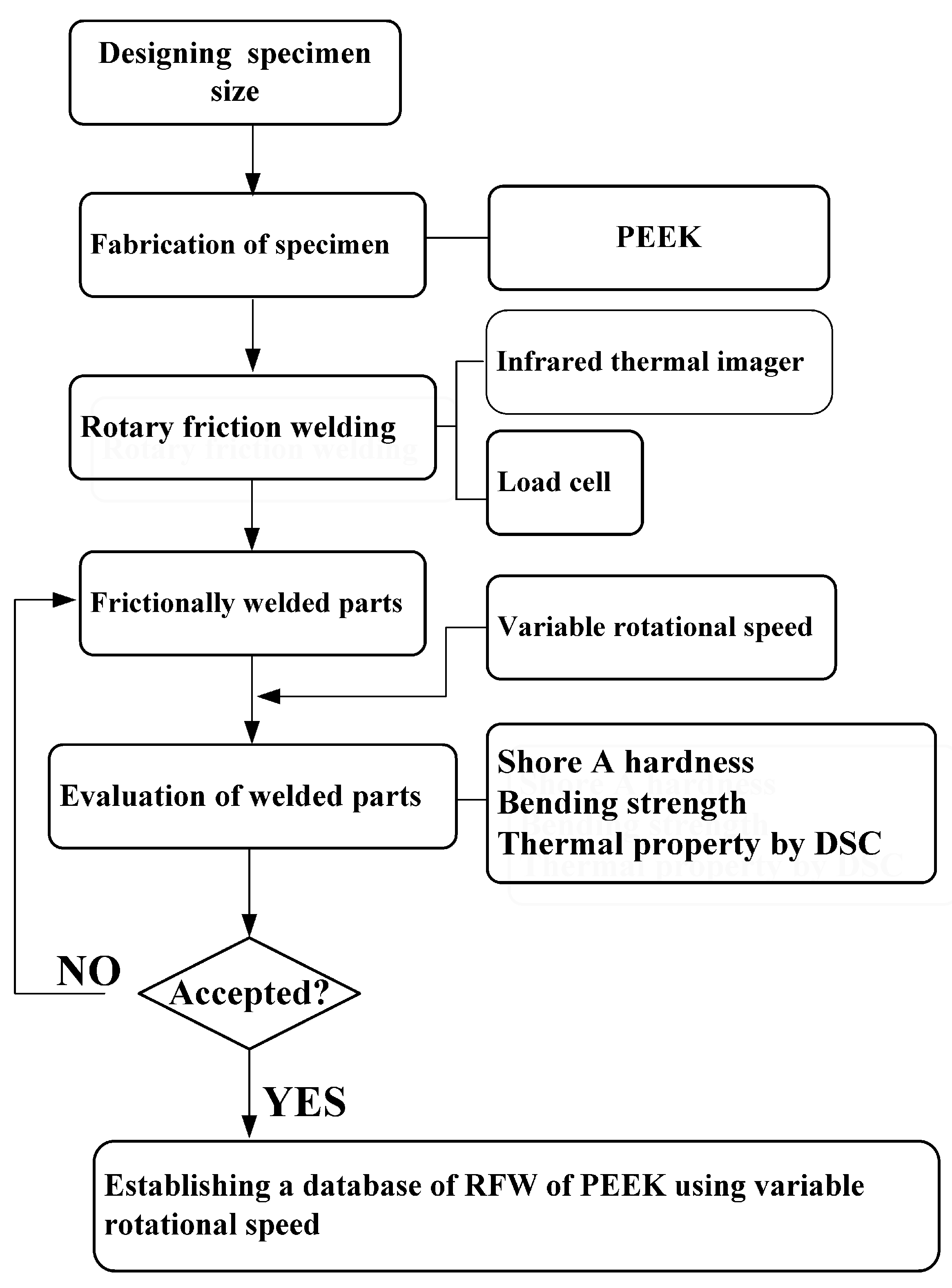
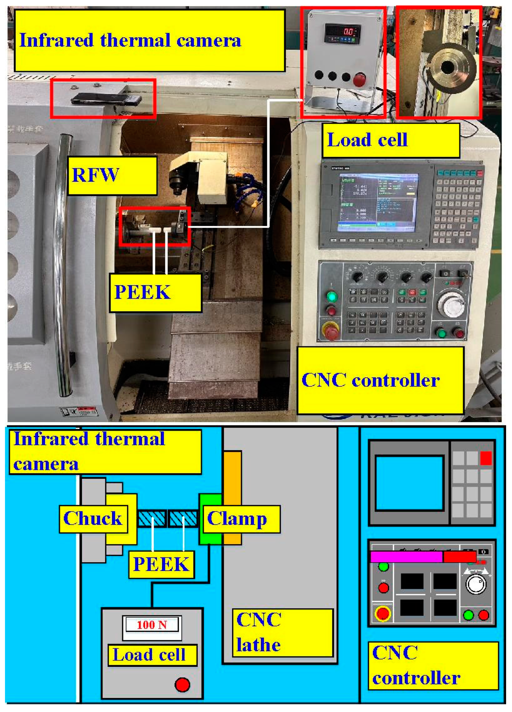
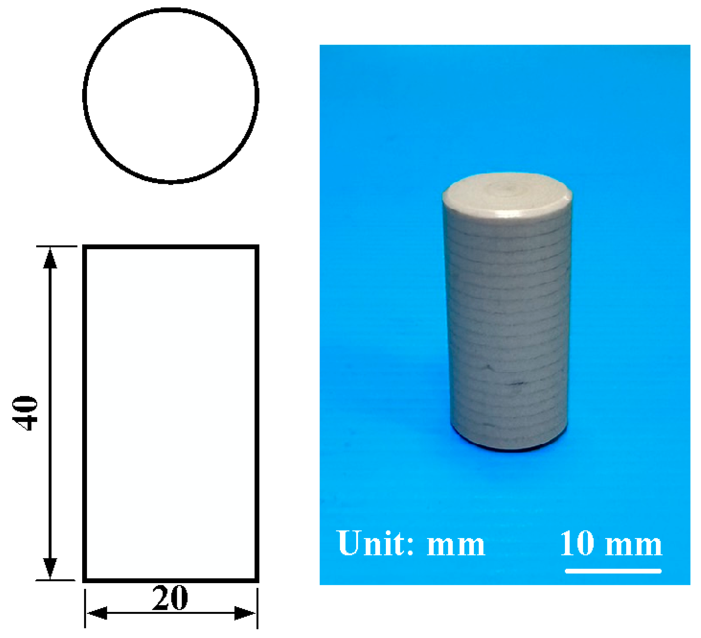
2. Experimental Details
3. Results and Discussion
4. Conclusions
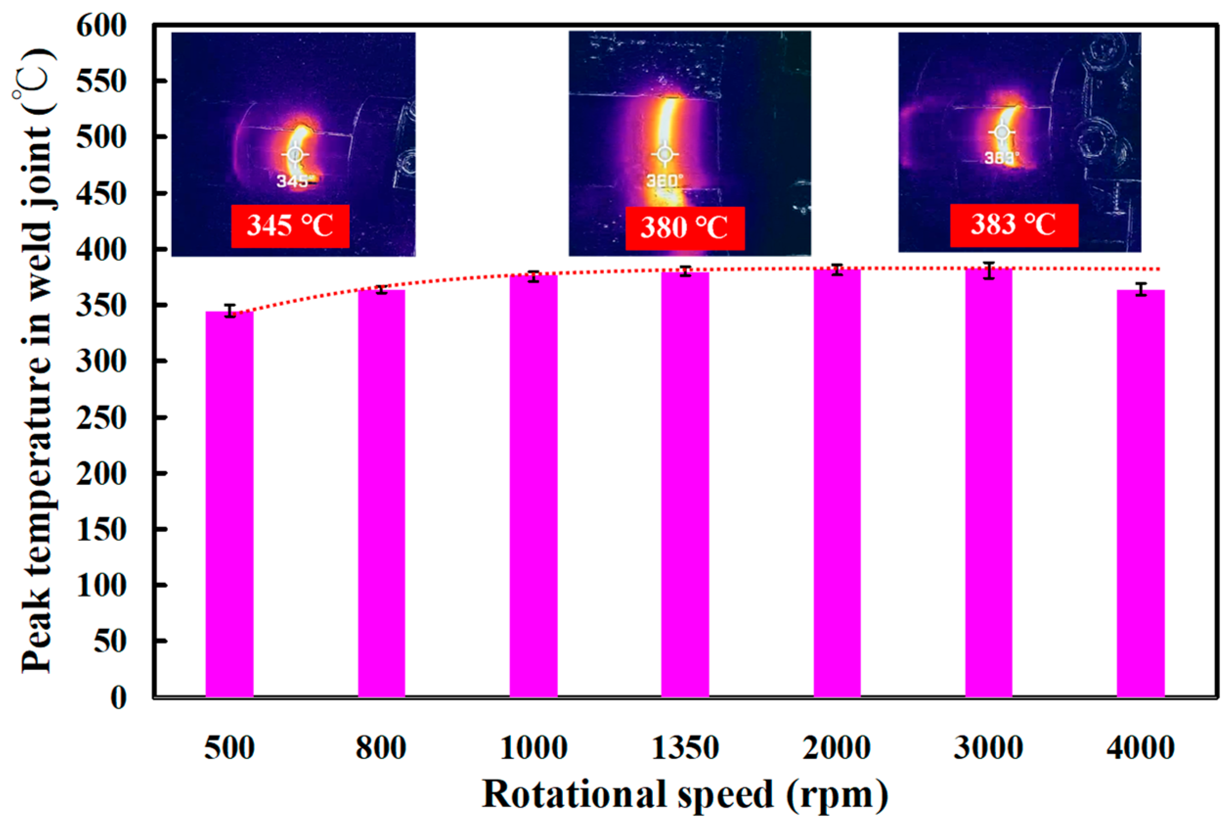
- The average peak temperature in the weld joint for rotational speeds of 1000 rpm, 1350 rpm, 2000 rpm, 3000 rpm, and 4000 rpm was about 377 °C, which is about 40 °C higher than the melting point of PEEK. The average peak temperature of the weld bead is slightly lower when the rotational speed of RFW is 4000 rpm. The main reason is that the high rotational speed causes air convection, accelerating the cooling of the peak temperature in the weld joint during RFW.
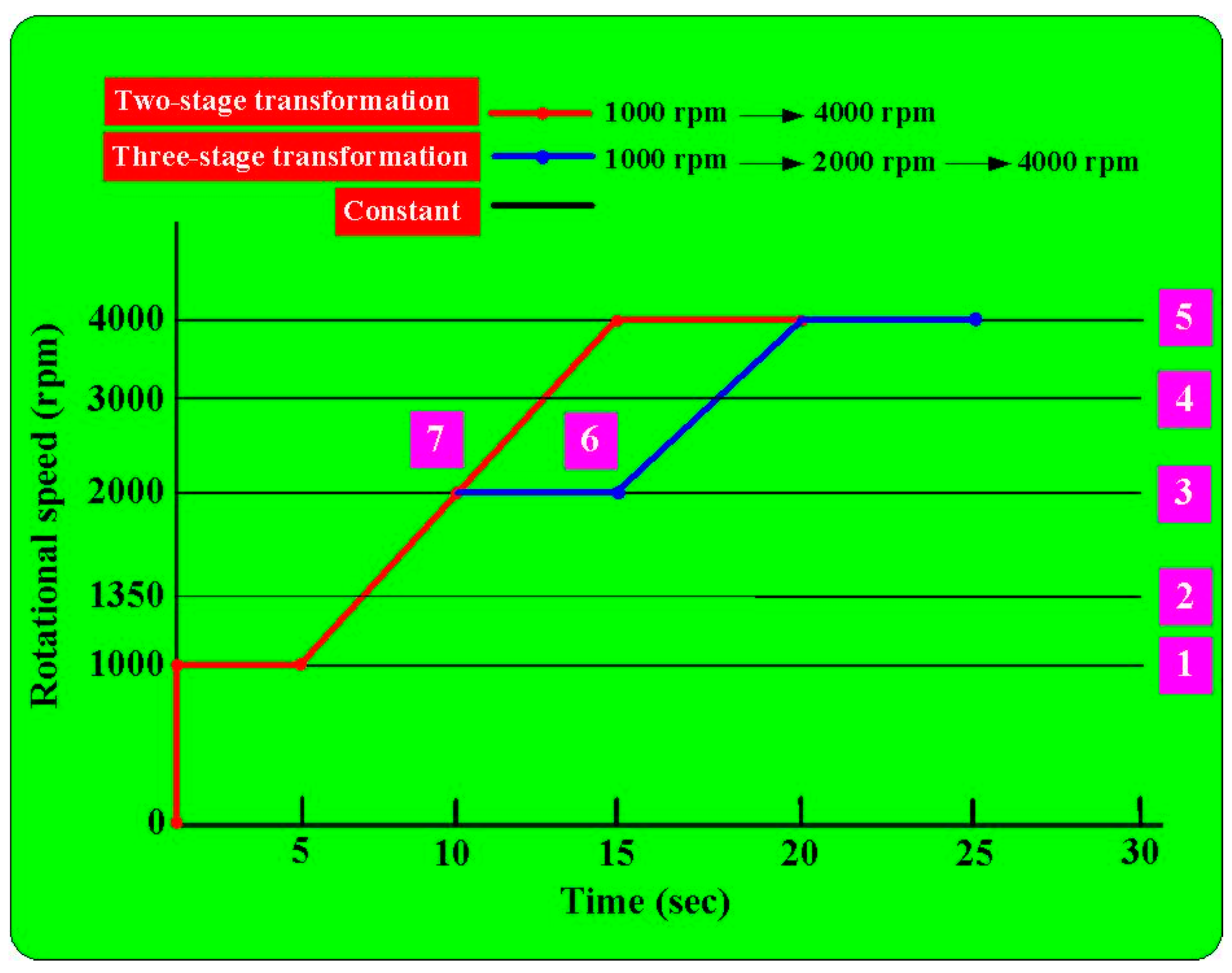
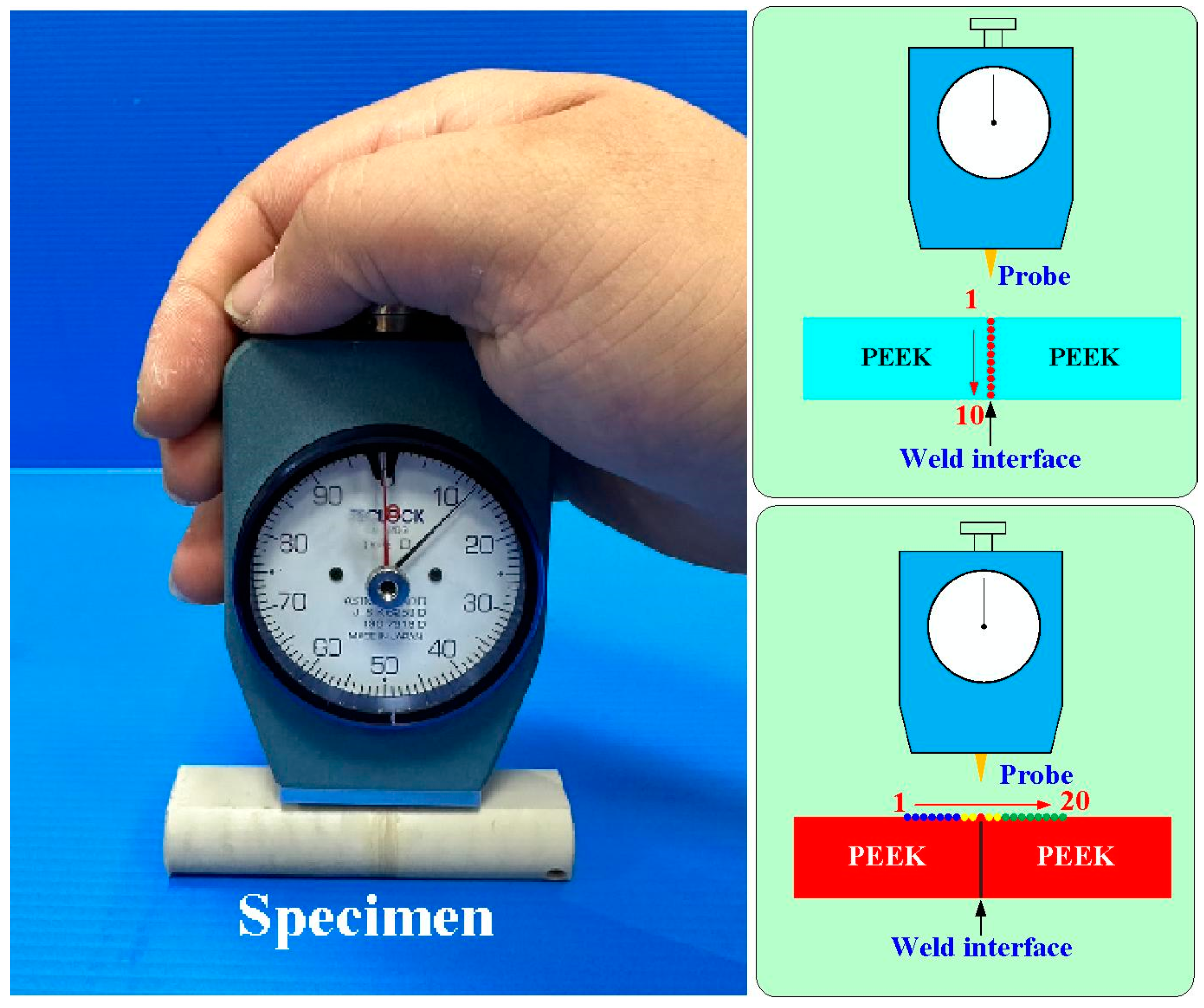
- For the two-stage transformation of RFW, the weld joint temperature can reach about 258 °C in the friction zone and the weld joint temperature can reach about 353 °C in the welding zone. For the two-stage transformation of RFW, the weld joint temperature can reach about 260 °C in the friction zone and the weld joint temperature can reach about 373 °C in the welding zone.
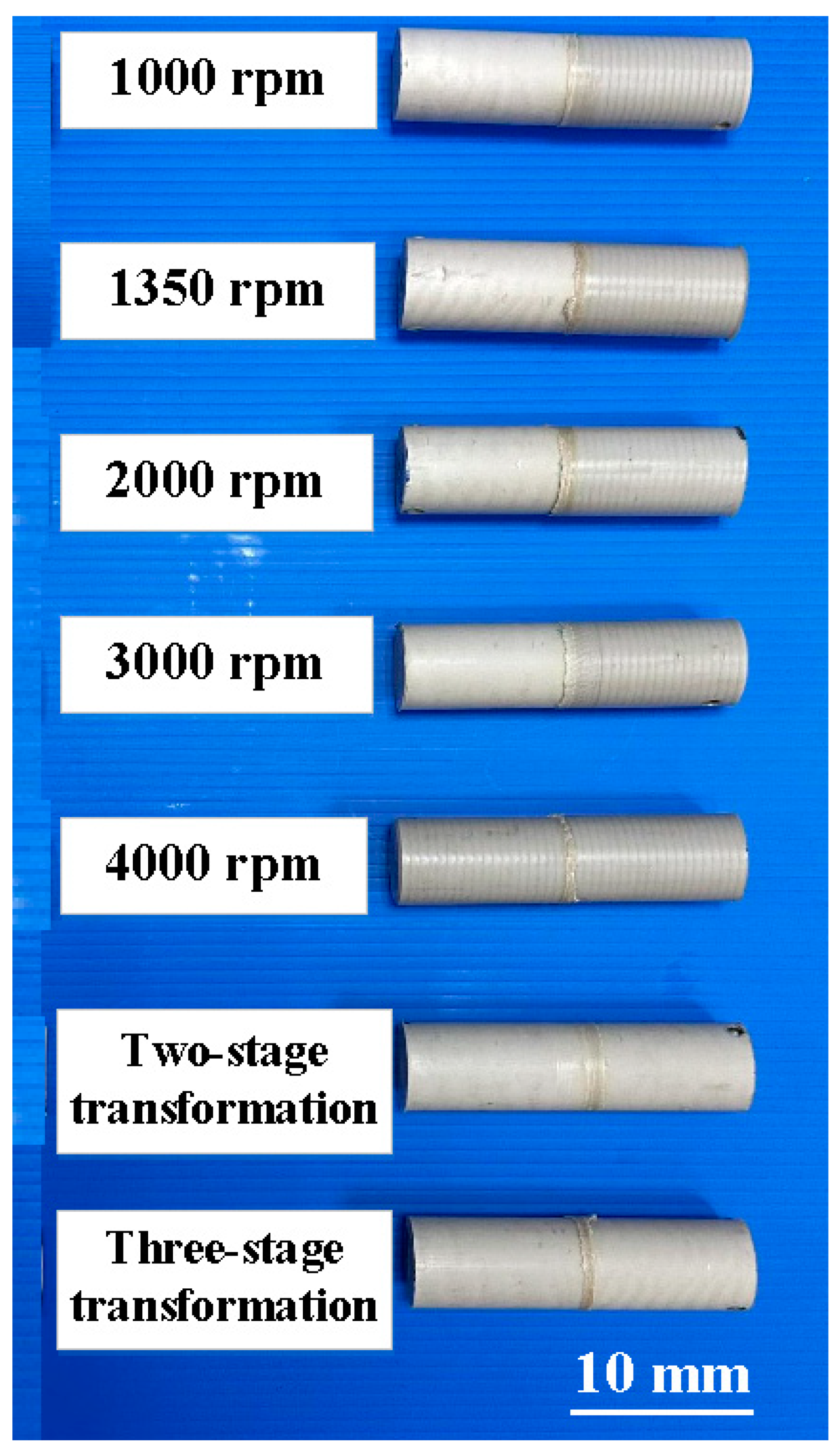
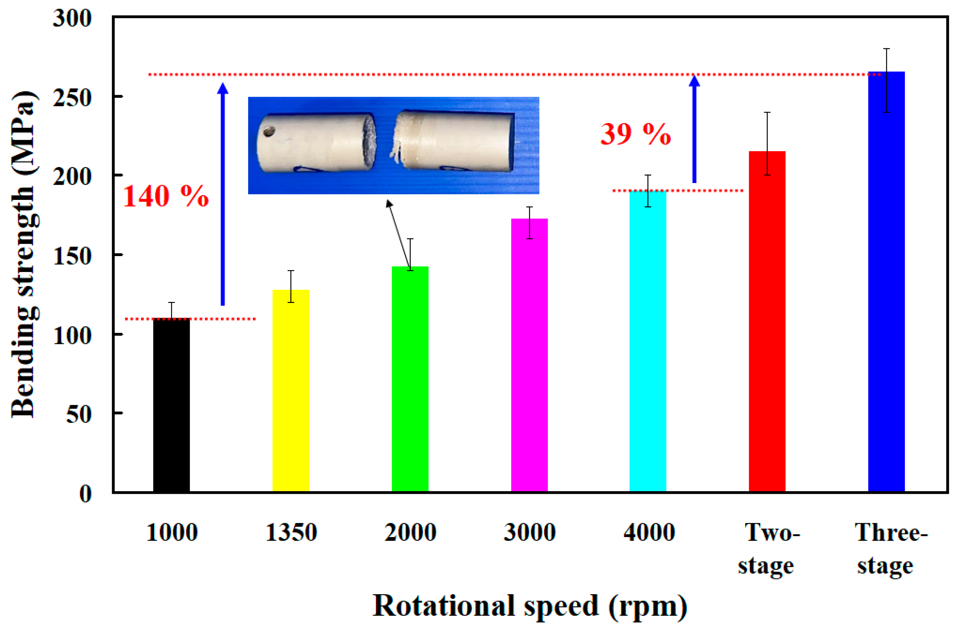
- The average bending strength of the welded part using three-stage transformation rotational speed was enhanced by about 140%, 107%, 85%, 53%, and 39% compared with five fixed rotational speeds. A reduction in the cycle time of about 6% can be obtained using a three-stage transformation rotational speed.
Author Contributions
Funding
Institutional Review Board Statement
Data Availability Statement
Conflicts of Interest
References
- Lambiase, F.; Grossi, V.; Paoletti, A. Effect of tilt angle in FSW of polycarbonate sheets in butt configuration. Int. J. Adv. Manuf. Technol. 2020, 107, 489–501. [Google Scholar] [CrossRef]
- Delijaicov, S.; Rodrigues, M.; Farias, A.; Neves, M.D.; Bortolussi, R.; Miyazaki, M.; Brandão, F. Microhardness and residual stress of dissimilar and thick aluminum plates AA7181-T7651 and AA7475-T7351 using bobbin, top, bottom, and double-sided FSW methods. Int. J. Adv. Manuf. Technol. 2020, 108, 277–287. [Google Scholar] [CrossRef]
- Hassan, A.J.; Boukharouba, T.; Miroud, D. Concept of forge application under effect of friction time for AISI 316 using friction welding process. Int. J. Adv. Manuf. Technol. 2021, 112, 2223–2231. [Google Scholar] [CrossRef]
- Yin, P.; Xu, C.; Pan, Q.; Zhang, W.; Jiang, X. Effect of Different Ultrasonic Power on the Properties of RHA Steel Welded Joints. Materials 2022, 15, 768. [Google Scholar] [CrossRef]
- Li, B.; Liu, Q.; Jia, S.; Ren, Y.; Yang, P. Effect of V Content and Heat Input on HAZ Softening of Deep-Sea Pipeline Steel. Materials 2022, 15, 794. [Google Scholar] [CrossRef]
- Iftikhar, S.H.; Mourad, A.-H.I.; Sheikh-Ahmad, J.; Almaskari, F.; Vincent, S. A Comprehensive Review on Optimal Welding Conditions for Friction Stir Welding of Thermoplastic Polymers and Their Composites. Polymers 2021, 13, 1208. [Google Scholar] [CrossRef]
- Khalaf, H.I.; Al-Sabur, R.; Demiral, M.; Tomków, J.; Łabanowski, J.; Abdullah, M.E.; Derazkola, H.A. The Effects of Pin Profile on HDPE Thermomechanical Phenomena during FSW. Polymers 2022, 14, 4632. [Google Scholar] [CrossRef]
- Vidakis, N.; Petousis, M.; Korlos, A.; Mountakis, N.; Kechagias, J.D. Friction Stir Welding Optimization of 3D-Printed Acrylonitrile Butadiene Styrene in Hybrid Additive Manufacturing. Polymers 2022, 14, 2474. [Google Scholar] [CrossRef]
- Skowrońska, B.; Chmielewski, T.; Zasada, D. Assessment of Selected Structural Properties of High-Speed Friction Welded Joints Made of Unalloyed Structural Steel. Materials 2023, 16, 93. [Google Scholar] [CrossRef]
- Eliseev, A.; Osipovich, K.; Fortuna, S. Gradient Structure of the Transfer Layer in Friction Stir Welding Joints. Materials 2022, 15, 6772. [Google Scholar] [CrossRef]
- Anwar, S.; Rehman, A.U.; Usmani, Y.; Al-Samhan, A.M. Influence of Post Weld Heat Treatment on the Grain Size, and Mechanical Properties of the Alloy-800H Rotary Friction Weld Joints. Materials 2021, 14, 4366. [Google Scholar] [CrossRef]
- Rashed, K.; Kafi, A.; Simons, R.; Bateman, S. Optimization of material extrusion additive manufacturing process parameters for polyether ketone ketone (PEKK). Int. J. Adv. Manuf. Technol. 2023, 126, 1067–1091. [Google Scholar] [CrossRef]
- Miura, D.; Ishida, Y.; Shinya, A. The Effects of Different Molding Orientations, Highly Accelerated Aging, and Water Absorption on the Flexural Strength of Polyether Ether Ketone (PEEK) Fabricated by Fused Deposition Modeling. Polymers 2023, 15, 1602. [Google Scholar] [CrossRef] [PubMed]
- Kuo, C.-C.; Xu, J.-Y.; Lee, C.-H. Weld Strength of Friction Welding of Dissimilar Polymer Rods Fabricated by Fused Deposition Modeling. Polymers 2022, 14, 2582. [Google Scholar] [CrossRef] [PubMed]
- Sundaraselvan, S.; Senthilkumar, N.; Balamurugan, T.; Kaviarasu, C.; Sathishkumar, G.; Rajesh, M. Optimization of friction welding process parameters for Joining Al6082 and mild steel using RSM. Mater. Today Proc. 2023, 74 Pt 1, 91–96. [Google Scholar] [CrossRef]
- Kuo, C.-C.; Gurumurthy, N.; Chen, H.-W.; Hunag, S.-H. Mechanical Performance and Microstructural Evolution of Rotary Friction Welding of Acrylonitrile Butadiene Styrene and Polycarbonate Rods. Materials 2023, 16, 3295. [Google Scholar] [CrossRef]
- Bazani Shaik, G.; Harinath Gowd, B.; Prasad, D. Experimental and parametric studies with friction stir welding on aluminium alloys. Mater. Today Proc. 2019, 19 Pt 2, 372–379. [Google Scholar] [CrossRef]
- Kuo, C.-C.; Gurumurthy, N.; Chen, H.-W.; Hunag, S.-H. Experimentation and Numerical Modeling of Peak Temperature in the Weld Joint during Rotary Friction Welding of Dissimilar Plastic Rods. Polymers 2023, 15, 2124. [Google Scholar] [CrossRef]
- Kuo, C.-C.; Chen, H.-W.; Xu, J.-Y.; Lee, C.-H.; Hunag, S.-H. Effects of Rotational Speed on Joint Characteristics of Green Joining Technique of Dissimilar Polymeric Rods Fabricated by Additive Manufacturing Technology. Polymers 2022, 14, 4822. [Google Scholar] [CrossRef]
- Nagu, K.; Kumar, A. Effect of tool rotational speed on microstructure and mechanical properties of friction stir welded AA6061-T6 alloy using brass interlayer. Mater. Today Proc. 2020, 33 Pt 8, 5486–5491. [Google Scholar] [CrossRef]
- Mehri, A.; Abdollah-Zadeh, A.; Habibi, N.; Hajian, M.; Wang, J.T. The Effects of Rotational Speed on Microstructure and Mechanical Properties of Friction Stir-Welded 7075-T6 Thin Sheet. J. Mater. Eng. Perform. 2020, 29, 2316–2323. [Google Scholar] [CrossRef]
- Palaniappan, S.P.; Muthukumar, K.; Sabariraj, R.V.; Kumar, S.D.; Sathish, T. CNC turning process parameters optimization on Aluminium 6082 alloy by using Taguchi and ANOVA. Mater. Today Proc. 2020, 21 Pt 1, 1013–1021. [Google Scholar] [CrossRef]
- Zlatanovic, D.L.; Bergmann, J.P.; Balos, S.; Gräzel, M.; Pejic, D.; Sovilj, P.; Goel, S. Influence of rotational speed on the electrical and mechanical properties of the friction stir spot welded aluminium alloy sheets. Weld. World 2022, 66, 1179–1190. [Google Scholar] [CrossRef]
- Zhou, L.; Yu, M.; Jiang, Z.; Guo, F.; Zhao, H.; Huang, Y.; Song, X. Influence of Rotation Speed on Microstructure and Mechanical Properties of Friction Stir Lap Welded Joints of AA 6061 and Ti6Al4V Alloys. Met. Mater. Trans. A 2019, 50, 733–745. [Google Scholar] [CrossRef]
- Sasmito, A.; Ilman, M.N.; Iswanto, P.T.; Muslih, R. Effect of Rotational Speed on Static and Fatigue Properties of Rotary Friction Welded Dissimilar AA7075/AA5083 Aluminium Alloy Joints. Metals 2022, 12, 99. [Google Scholar] [CrossRef]
- Raguraman, D.; Balu, P.; Manavalan, S.; Raja, E. Multi-linear optimization of machining parameters of CNC turning of AA6061alloy using GRA method. Mater. Today Proc. 2023, in press. [Google Scholar] [CrossRef]
- Bokam, V.K.; Sonaye, S.Y.; Nagaraju, P.; Naganaboyina, H.P.; Sikder, P. Effect of milling on the compounding of poly-ether-ether ketone (PEEK) and amorphous magnesium phosphate (AMP) composites. Powder Technol. 2023, 427, 118747. [Google Scholar] [CrossRef]
- Toro, S.A.; Ridruejo, A.; González, C.; Monclús, M.A.; Fernández-Blázquez, J.P. Optimization of Processing Conditions and Mechanical Properties for PEEK/PEI Multilayered Blends. Polymers 2022, 14, 4597. [Google Scholar] [CrossRef]
- Mir, F.A.; Khan, N.Z.; Siddiquee, A.N.; Parvez, S. Friction based solid state welding—A review. Mater. Today Proc. 2022, 62 Pt 1, 55–62. [Google Scholar]
- Wu, F.; Flint, T.; Kindermann, R.M.; Roy, M.J.; Yang, L.; Robertson, S.; Zhou, Z.; Smith, M.; Shanthraj, P.; English, P.; et al. Evolution and formation of dissimilar metal interfaces in fusion welding. Acta Mater. 2023, 258, 119232. [Google Scholar] [CrossRef]
- Belioka, M.-P.; Markozanne, G.; Chrissopoulou, K.; Achilias, D.S. Advanced Plastic Waste Recycling—The Effect of Clay on the Morphological and Thermal Behavior of Recycled PET/PLA Sustainable Blends. Polymers 2023, 15, 3145. [Google Scholar] [CrossRef] [PubMed]
- Rennert, M.; Hiller, B.T. Influence of Coffee Variety and Processing on the Properties of Parchments as Functional Bioadditives for Biobased Poly (butylene succinate) Composites. Polymers 2023, 15, 2985. [Google Scholar] [CrossRef] [PubMed]
- Wang, J.; Lu, Y.; Han, J.; Qi, J.; Sun, L.; Jiang, Z.; Ma, C.; Linton, V. Study on microstructure evolution and mechanical properties of high-strength low-alloy steel welds realized by flash butt welding thermomechanical simulation. Int. J. Adv. Manuf. Technol. 2022, 122, 639–658. [Google Scholar] [CrossRef]
- Salamati, M.; Soltanpour, M.; Fazli, A. Processing and tooling considerations in joining by forming technologies; part B—Friction-based welding. Int. J. Adv. Manuf. Technol. 2020, 106, 4023–4081. [Google Scholar] [CrossRef]
- Rehman, M.A.U.; Batool, S.A. Development of sustainable antibacterial coatings based on electrophoretic deposition of multilayers: Gentamicin-loaded chitosan/gelatin/bioactive glass deposition on PEEK/bioactive glass layer. Int. J. Adv. Manuf. Technol. 2022, 120, 3885–3900. [Google Scholar] [CrossRef]
- Oladapo, B.; Zahedi, A.; Ismail, S.; Fernando, W.; Ikumapayi, O. 3D-printed biomimetic bone implant polymeric composite scaffolds. Int. J. Adv. Manuf. Technol. 2023, 126, 4259–4267. [Google Scholar] [CrossRef]
- Khatri, B.; Roth, M.F.; Balle, F. Ultrasonic Welding of Additively Manufactured PEEK and Carbon-Fiber-Reinforced PEEK with Integrated Energy Directors. J. Manuf. Mater. Process. 2023, 7, 2. [Google Scholar] [CrossRef]
- Alexenko, V.O.; Panin, S.V.; Stepanov, D.Y.; Byakov, A.V.; Bogdanov, A.A.; Buslovich, D.G.; Panin, K.S.; Tian, D. Ultrasonic Welding of PEEK Plates with CF Fabric Reinforcement—The Optimization of the Process by Neural Network Simulation. Materials 2023, 16, 2115. [Google Scholar] [CrossRef]
- Bonmatin, M.; Chabert, F.; Bernhart, G.; Cutard, T.; Djilali, T. Ultrasonic welding of CF/PEEK composites: Influence of welding parameters on interfacial temperature profiles and mechanical properties. Compos. Part A Appl. Sci. Manuf. 2022, 162, 107074. [Google Scholar] [CrossRef]
- Abdul-Rashid, S.H.; Mohamad, M.N.; Sakundarini, N.; Ghazilla, R.A.R.; Thurasamy, R. Modelling sustainable manufacturing practices effects on sustainable performance: The contingent role of ownership. Int. J. Adv. Manuf. Technol. 2022, 122, 3997–4012. [Google Scholar] [CrossRef]
- Tian, S.; Xie, X.; Xu, W.; Liu, J.; Zhang, X. Dynamic assessment of sustainable manufacturing capability based on correlation relationship for industrial cloud robotics. Int. J. Adv. Manuf. Technol. 2023, 124, 3113–3135. [Google Scholar] [CrossRef]
- Klimant, P.; Koriath, H.-J.; Schumann, M.; Winkler, S. Investigations on digitalization for sustainable machine tools and forming technologies. Int. J. Adv. Manuf. Technol. 2021, 117, 2269–2277. [Google Scholar] [CrossRef]
- Zhou, L.; Zhou, J.; Huang, P.; Zhang, G.; Lin, Z.; Zhao, Z.; Huang, Y.; Jiao, H.; Long, Y. Study on the mechanism of quasi-continuous wave (QCW) fiber laser low-damage processing of carbon fiber-reinforced plastics. Int. J. Adv. Manuf. Technol. 2023, 124, 429–447. [Google Scholar] [CrossRef]
- Liu, S.Q.; Han, S.W.; Hwang, T.W.; Abolhasani, D.; Moon, Y.H. Design and application of laser scanning strategy for machining deep surface grooves with a continuous-wave fiber laser. Int. J. Adv. Manuf. Technol. 2023, 127, 4133–4147. [Google Scholar] [CrossRef]
- Rushworth, A.G.A.; Xie, K.G.; Fang, B.L.; Shen, Y.X.; Huang, Z.P.; Zhang, X.Y. Generating Profiled Diamond Grinding Wheels by 2000 W Fiber Laser: On the Understanding of Laser Ablation Law with High Power and Establishment of a Predictive Model. Int. J. Adv. Manuf. Technol. 2022, 120, 3045–3063. [Google Scholar] [CrossRef]
- Luo, Y.; Zhu, X.; Zhang, W.; Chang, C.; Gao, S.; Lu, B.; Yan, X. Modeling of tow-to-spot diameter ratio for laser cutting of single-layer carbon fiber–reinforced plastics (CFRP). Int. J. Adv. Manuf. Technol. 2023, 127, 4439–4452. [Google Scholar] [CrossRef]
- Moritz, J.; Seidel, A.; Kopper, M.; Bretschneider, J.; Gumpinger, J.; Finaske, T.; Riede, M.; Schneeweiß, M.; López, E.; Brückner, F.; et al. Hybrid manufacturing of titanium Ti-6Al-4V combining laser metal deposition and cryogenic milling. Int. J. Adv. Manuf. Technol. 2020, 107, 2995–3009. [Google Scholar] [CrossRef]
- Mansour, H.; Soliman, E.A.; El-Bab, A.M.F.; Abdel-Mawgood, A.L. Development of epoxy resin-based microfluidic devices using CO2 laser ablation for DNA amplification point-of-care (POC) applications. Int. J. Adv. Manuf. Technol. 2022, 120, 4355–4372. [Google Scholar] [CrossRef]
- Li, Y.; Geng, S.; Gu, S.; Huang, D.; Wang, Y.; Mi, G.; Jiang, P. Effect of liquid column on process stability and weld formation under ultra-high power fiber laser-arc hybrid welding of thick plates. Int. J. Adv. Manuf. Technol. 2022, 121, 8243–8255. [Google Scholar] [CrossRef]
- Ribeiro, C.A.C.; Ferreira, J.R.; Lima e Silva, S.M.M. Thermal influence analysis of coatings and contact resistance in turning cutting tool using COMSOL. Int. J. Adv. Manuf. Technol. 2022, 118, 275–289. [Google Scholar] [CrossRef]
- Schorr, L.; Johnson, B.; McFall, J.; Shepherd, D.; Hadimani, R.L. High-temperature gripper for collaborative robots in additive manufacturing. Int. J. Adv. Manuf. Technol. 2023, 128, 1291–1303. [Google Scholar] [CrossRef]
- Yang, C.; Wei, J.; Chen, Z.; Qu, S.; Han, X. Study of fracture damage criteria and influence of process parameters on punching of hot stamped ultra-high strength steel. Int. J. Adv. Manuf. Technol. 2023, 128, 1493–1504. [Google Scholar] [CrossRef]
- Yao, M.; Kong, F.; Tong, W. A 3D finite element analysis of thermally induced residual stress distribution in stainless steel coatings on a mild steel by laser hot wire cladding. Int. J. Adv. Manuf. Technol. 2023, 126, 759–776. [Google Scholar] [CrossRef]


Disclaimer/Publisher’s Note: The statements, opinions and data contained in all publications are solely those of the individual author(s) and contributor(s) and not of MDPI and/or the editor(s). MDPI and/or the editor(s) disclaim responsibility for any injury to people or property resulting from any ideas, methods, instructions or products referred to in the content. |
© 2023 by the authors. Licensee MDPI, Basel, Switzerland. This article is an open access article distributed under the terms and conditions of the Creative Commons Attribution (CC BY) license (https://creativecommons.org/licenses/by/4.0/).
Share and Cite
Kuo, C.-C.; Liang, H.-X.; Huang, S.-H.; Tseng, S.-F. Rotary Friction Welding of Polyetheretherketone Biopolymer Rods Using Variable Rotational Speed. Polymers 2023, 15, 4077. https://doi.org/10.3390/polym15204077
Kuo C-C, Liang H-X, Huang S-H, Tseng S-F. Rotary Friction Welding of Polyetheretherketone Biopolymer Rods Using Variable Rotational Speed. Polymers. 2023; 15(20):4077. https://doi.org/10.3390/polym15204077
Chicago/Turabian StyleKuo, Chil-Chyuan, Hua-Xhin Liang, Song-Hua Huang, and Shih-Feng Tseng. 2023. "Rotary Friction Welding of Polyetheretherketone Biopolymer Rods Using Variable Rotational Speed" Polymers 15, no. 20: 4077. https://doi.org/10.3390/polym15204077
APA StyleKuo, C.-C., Liang, H.-X., Huang, S.-H., & Tseng, S.-F. (2023). Rotary Friction Welding of Polyetheretherketone Biopolymer Rods Using Variable Rotational Speed. Polymers, 15(20), 4077. https://doi.org/10.3390/polym15204077