
Study on Deterioration Characteristics of a Composite Crossarm Mandrel in a 10 kV Distribution Network Based on Multi-Factor Aging

 ,
,
Abstract
:1. Introduction
2. Experiment
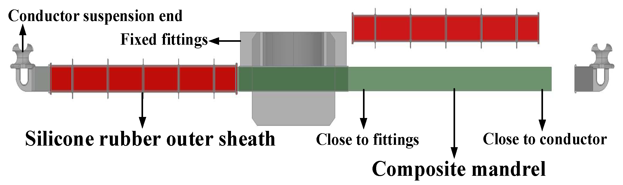
2.1. Materials
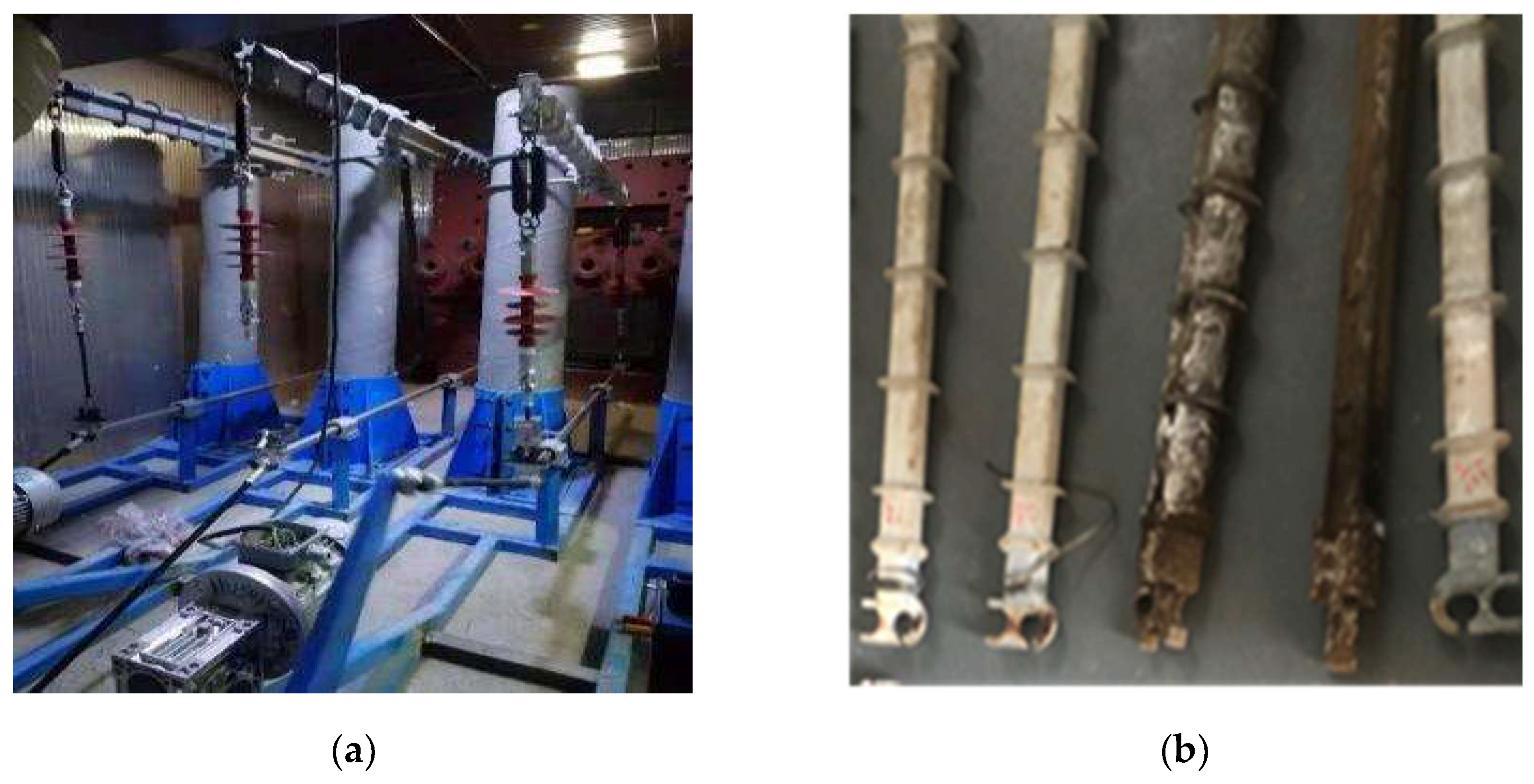
2.2. Multi-Factor Aging Test of the Composite Crossarm
2.3. Hydrophobic Property Test of Outer Sheath of Composite Crossarm after Aging
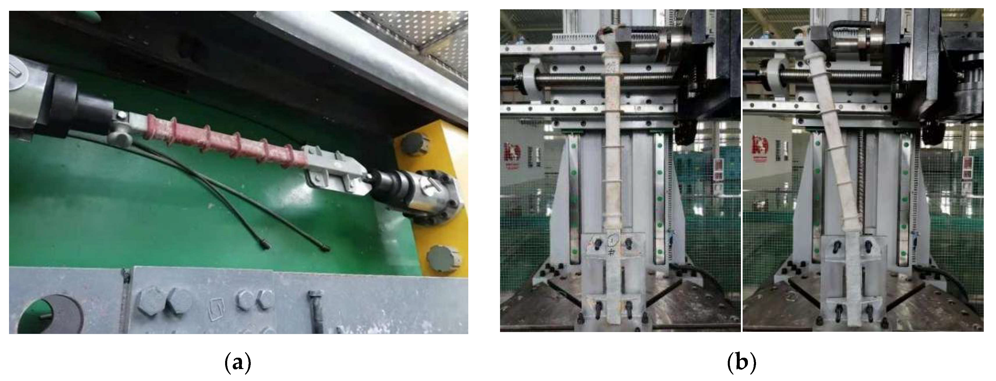
2.4. Test of Mechanical Properties of the Full-Size Composite Crossarm
2.5. Performance Test of the Composite Crossarm Mandrel Material
- (1)
- Mechanical test
- (2)
- Moisture absorption rate
- (3)
- Electrical test
- (4)
- TGA
- (5)
- SEM analysis and 3D CT nondestructive testing
3. Analysis and Discussion of Experimental Results
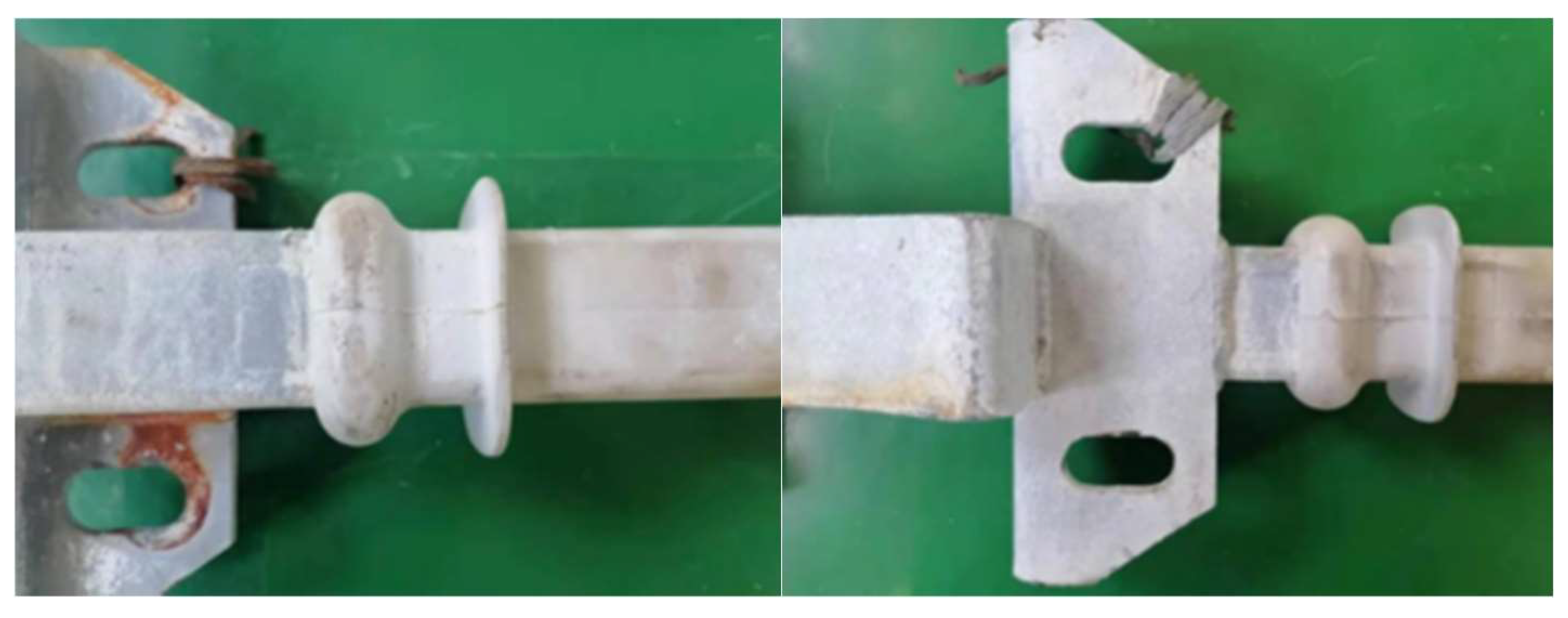
3.1. Mechanical Properties Test of the Full-Size Composite Crossarm
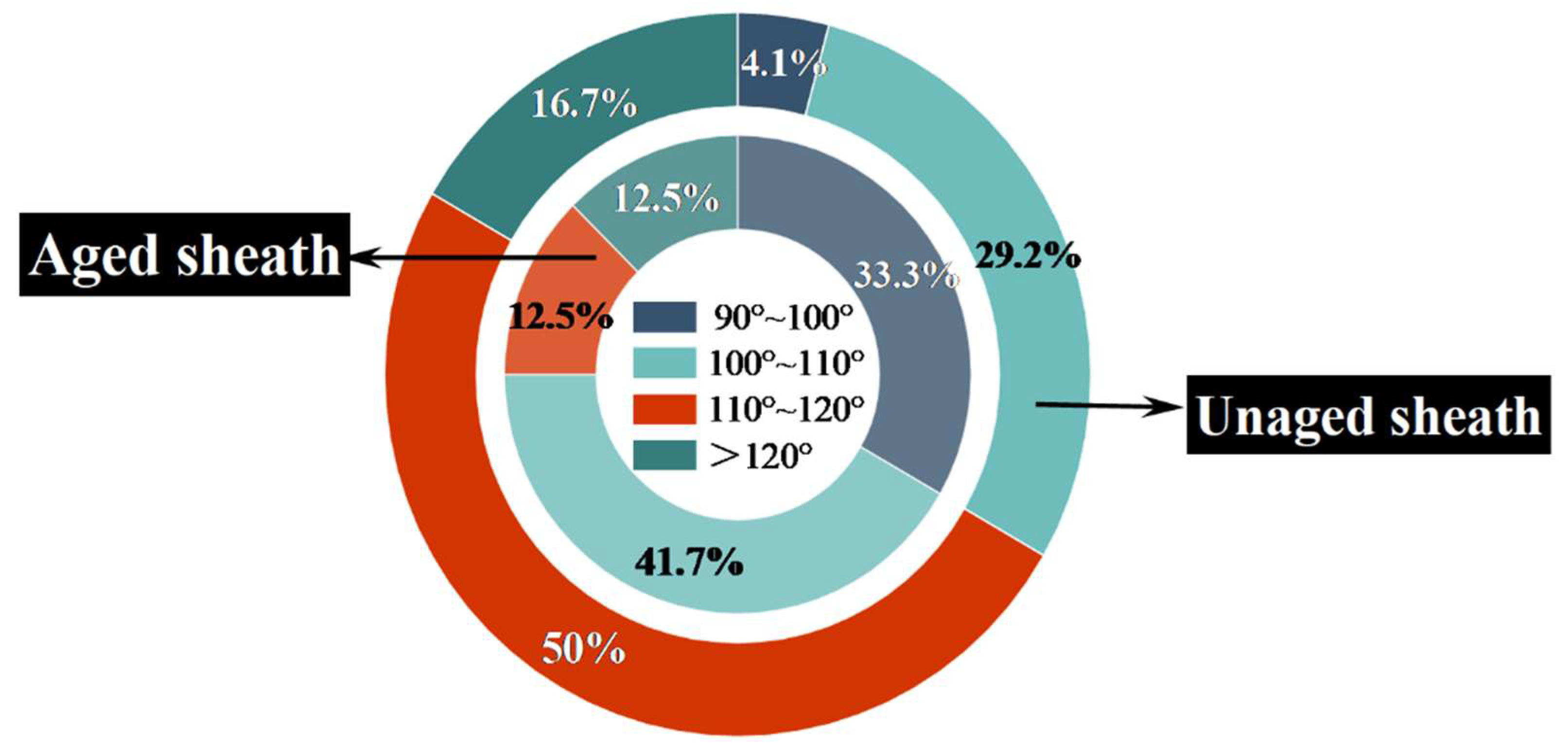
3.2. Hydrophobic Characteristics of the Outer Sheath of the Composite Crossarm after Aging
3.3. Macroscopic Characteristics of the Composite Crossarm Mandrel
- (1)
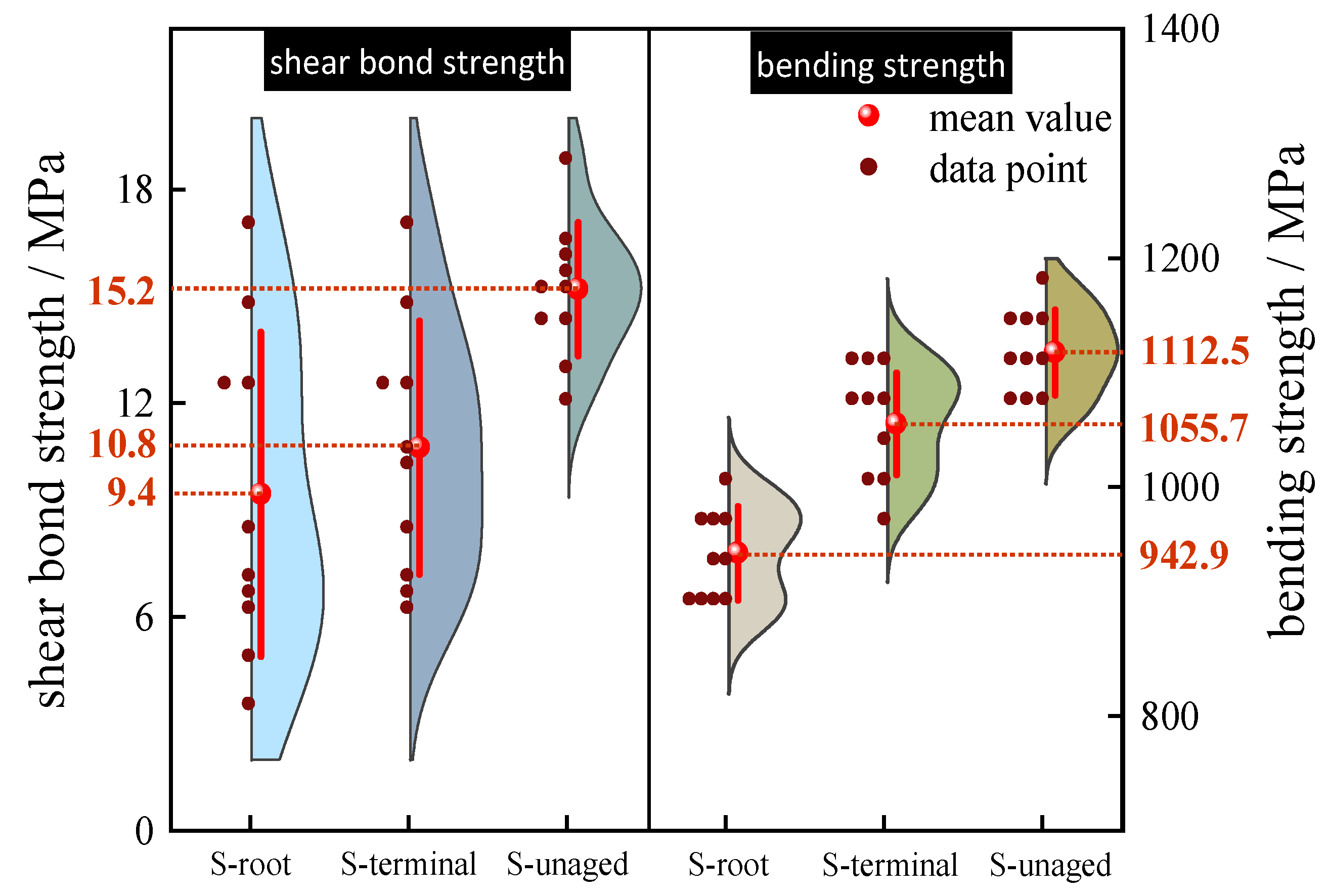
- Mechanical test
- (2)
- Moisture absorption rate
- (3)
- Electrical performance test and 3D CT scanning
3.4. Micro-Properties of the Composite Crossarm Mandrel
- (1)
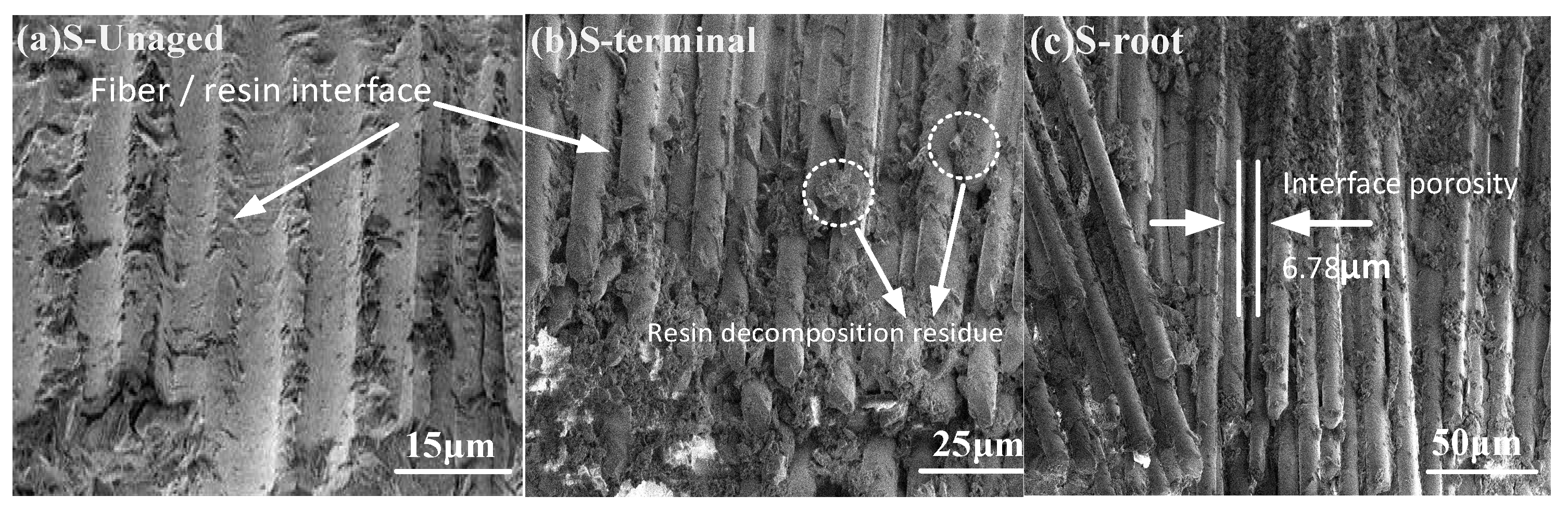
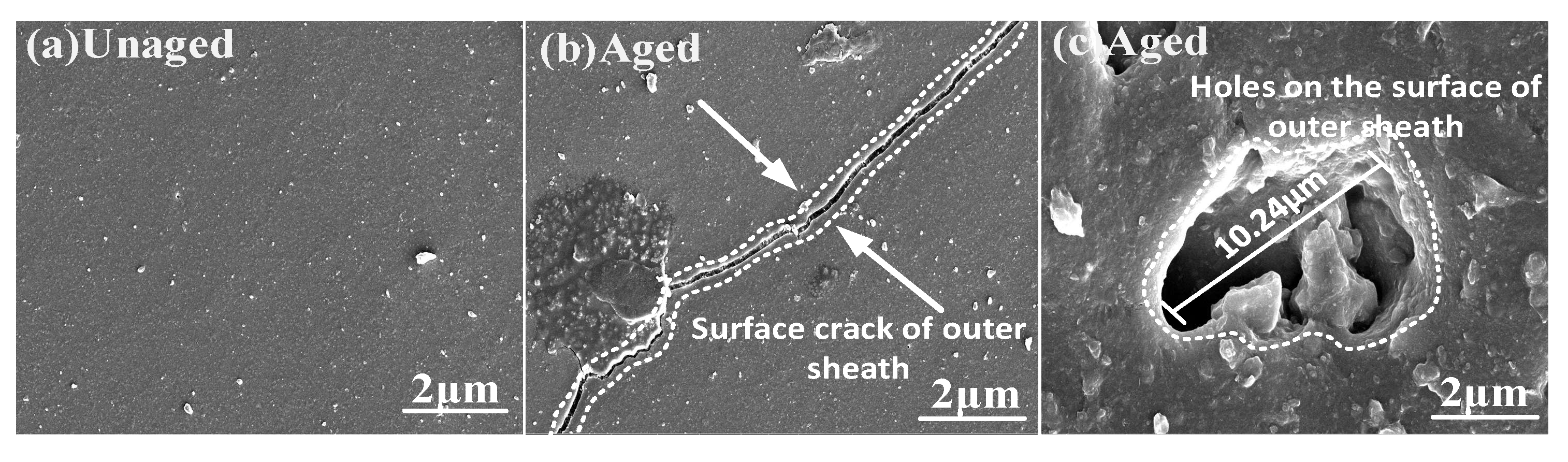
- SEM
- (2)
- TGA
3.5. Multi-Factor Aging Mechanism Analysis of the Composite Crossarm
- (1)
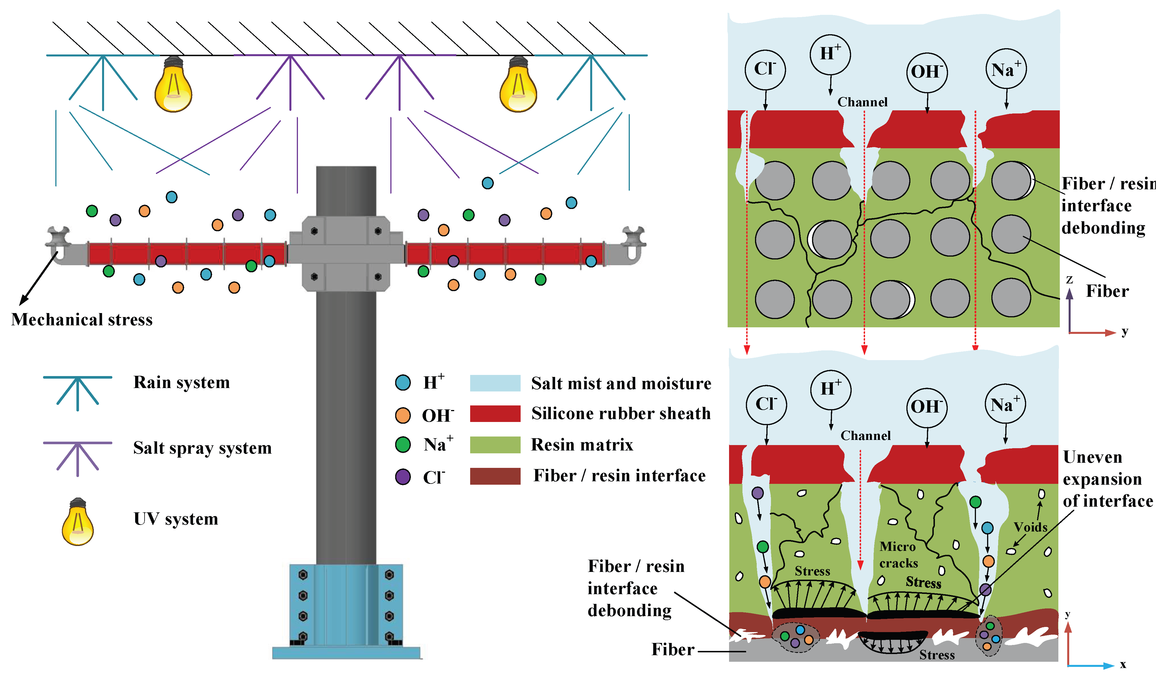
- Outer sheath aging. The composite crossarm worked under multi-factor aging for 5000 h. The main chain of Si-O-Si in the material broke due to rain, high temperatures, salt spray corrosion, and UV irradiation. The hydrophobic group Si-CH3 decreased and the hydrophilic group OH increased [22,23], resulting in a decrease in the hydrophobicity of the silicone rubber sheath. At the same time, the mechanical fatigue vibration will also aggravate the cracking of the outer sheath. According to the results of SEM, there are cracks and holes on the surface of silicone rubber, which provide a diffusion channel for H2O, Na+, and Cl− to invade the mandrel.
- (2)
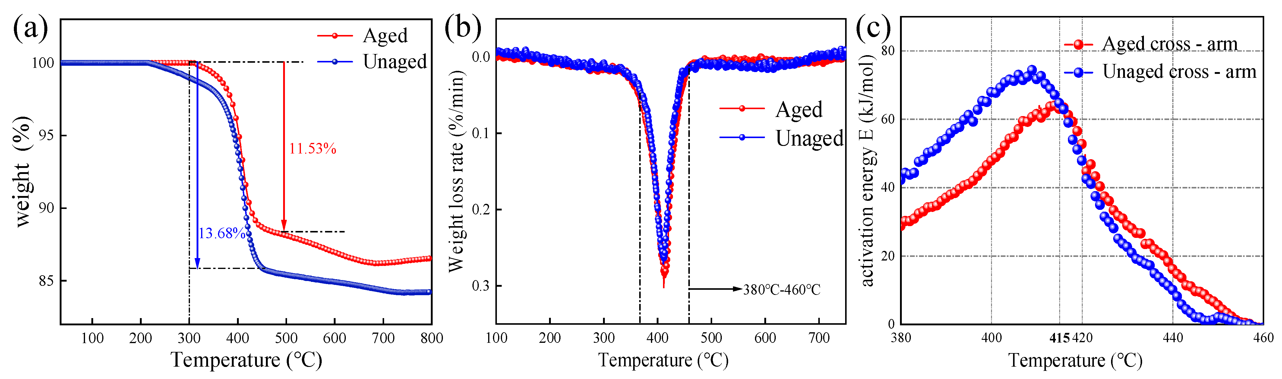
- Mandrel material aging. In terms of the resin matrix, TG test results show that after H2O, Na+, and Cl− penetrate into the mandrel through the damaged outer sheath, a small amount of the resin matrix decomposes and the molecular chain breaks under the combined aging of rain and high temperature, resulting in a decline in its thermal stability. At the same time, the continuously humid and hot environment will also increase the plasticity and reduce the stiffness of the resin matrix. For the fiber/resin interface, moisture and other ions infiltrating into the mandrel will cause uneven expansion in the humid and hot environment, resulting in interfacial debonding. From the results of three-dimensional CT and SEM, under the long-term action of high temperature, high humidity, and high salt accompanied by mechanical load, there are microcracks and pores in the resin matrix and fiber/resin interface, and local defects have a trend toward connectivity. This will affect the macroscopic mechanical properties, electrical properties, and moisture absorption characteristics of the core shaft material to a certain extent.
4. Conclusions
- (1)
- The tensile strength and bending strength of the full-scale composite crossarm after aging decreased by only 7.74%, still well above the rated load during normal operation, meeting operational requirements. However, the overall mechanical strength design margin of the composite crossarm is relatively large. In areas where the natural environment aligns with the multi-factor aging system parameters in this study, a moderate reduction in the margin is feasible.
- (2)
- After aging, the hydrophobicity of the composite crossarm’s outer sheath decreases, leading to the appearance of cracks and holes on the surface. This allows a small amount of moisture from the outside to penetrate into the mandrel through the sheath. For coastal environments, it is crucial to focus on enhancing the quality of the outer sheath to effectively protect the internal mandrel.
- (3)
- The test results of mandrel materials suggest that improving the bonding strength and thermal stability of the fiber-resin interface can help reduce the formation of defects, such as internal pores in the crossarm, in harsh environments. This improvement contributes to enhancing the mechanical and electrical strength of the composite crossarm.
Author Contributions
Funding
Data Availability Statement
Conflicts of Interest
References
- Wu, X.; Cai, W.; Li, J.; Sun, Q.; Zhu, X.; He, C.; Ke, R. Application progress of power fiber reinforced composites. Compos. Mater. Sci. Eng. 2021, 11, 116–128. [Google Scholar]
- Ke, R.; Du, T.; He, C.L.; Zhu, X.D.; Dong, Z.Q.; Guo, W. Ageing Characteristics of Composite Insulation Cross-arm for Distribution Network. Insul. Mater. 2019, 52, 36–40. [Google Scholar]
- Tian, L.; Zhang, Z.J.; Ma, X.H. Characteristics of Powdered Layer on Silicone Rubber Surface. J. Mater. Res. Technol. 2021, 5, 36–46. [Google Scholar]
- Hou, S.Z.; Zhong, Z.; Huang, Q.L. Simulation analysis of temperature rise and heat source of short sample of crisp composite insulator in high and low humidity environment. J. North China Electr. Power Univ. 2023, 50, 1–11. [Google Scholar]
- Nie, Z.X.; Wang, L.M.; Yang, C.R. Aging characteristics of the interface between core rod and sheath of composite insulator under the action of water and high temperature. Chin. J. Electr. Eng. 2018, 38, 4601-4611+4661. [Google Scholar]
- Mohamad, A.D.; Ahmet, E. UV accelerated aging and sewage sludge ash particle effects on mode I interlaminar fracture properties of glass fiber/epoxy composites. Iran. Polym. J. 2021, 30, 811–820. [Google Scholar]
- IEC/TR 62730-2012; HV Polymeric Insulators for Indoor and Outdoor Use Tracking and Erosion Testing by Wheel Test and 5000 h Test. International Electrotechnical Commission: Geneva, Switzerland, 2012.
- Peng, W.; Gou, X.; Qin, H.; Zhao, M.; Zhao, X.; Guo, Z. Robust Mg(OH)2/epoxy resin superhydrophobic coating applied to composite insulators. Appl. Surf. Sci. 2019, 466, 126–132. [Google Scholar] [CrossRef]
- Q/GDW 12069-2020; Technology Specification of Composite cross Arm of 10kV Distribution Line. STATE GRID Corporation of China: Beijing, China, 2020.
- ISO 14130-1997; Fibre-Reinforced Plastic Composites—Determination of Apparent Interlaminar Shear Strength by Short-Beam Method. ISO: Geneva, Switzerland, 1997.
- IEC 60243-1-2013; Electric Strength of Insulating Materials—Test Methods—Part 1: Tests at Power Frequencies. China National Standardization Administrative Committee: Beijing, China, 2013.
- Gautier, L.; Mortaigne, B.; Bellenger, V. Interface damage study of hydrothermally aged glass-®bre-reinforced polyester composites. Compos. Sci. Technol. 1999, 59, 2329–2337. [Google Scholar] [CrossRef]
- Hou, S.Z.; Zhong, Z.; Liu, Y.P. Numerical simulation of moisture absorption characteristics and wet stress distribution of GFRP material for high voltage composite insulator. Trans. China Electrotech. Soc. 2022, 37, 1010–1019. [Google Scholar]
- Zeng, L.L.; Zhang, Y.; Deng, Z.B. Study on hygrothermal aging characteristics of composite insulator core rod. Porcelain Arrester 2020, 2, 196–203. [Google Scholar] [CrossRef]
- Akil, H.M.; Cheng, L.W.; Mohd Ishak, Z.A.; Abu Bakar, A.; Abd Rahman, M.A. Water absorption study on pultruded jute fibre reinforced unsaturated polyester composites. Compos. Sci. Technol. 2009, 69, 1942–1948. [Google Scholar] [CrossRef]
- Yuan., Z.K. Deterioration Characteristics and Mechanism of Composite Insulator Materials in High Humidity Environment. Ph.D. Thesis, North China Electric Power University, Beijing, China, 2019. (In Chinese). [Google Scholar]
- Zhang, J.Z.; Chen, T.J.; Wua, J.L. A novel Gaussian-DAEM-reaction model for the pyrolysis of cellulose, hemicellulose and lignin. Rsc Adv. 2014, 4, 17513–17520. [Google Scholar] [CrossRef]
- Kinetics of thermal analysis, fundamentals and applications of calorimetry. Energetic Mater. 2011, 19, 744.
- Du, X.; Qin, Q.H.; Lei, H.S.; Yao, Y.; Li, H.M.; Fang, D.N. Preparation and mechanical properties characterization of new composite Miura structure. In Proceedings of the Third China International Conference on Composites Technology, Hangzhou, China, 21 October 2017. [Google Scholar]
- Guo, J.J.; Sun., J.L.; Ren., M.S. The most probable Malek method for analysis of curing mechanism of TDE-85/MeNA epoxy resin system. Compos. Sci. Eng. 2009, 6, 12–15. (In Chinese) [Google Scholar]
- Shen, H. Study on Degradation Mechanism of Core Rod Epoxy Resin in Brittle Fracture of Composite Insulator. Master’s Thesis, Shandong University, Jinan, China, 2020. [Google Scholar]
- Liang, X.; Bao, W.; Gao, Y. Decay-like Fracture Mechanism of Silicone Rubber Composite Insulator. IEEE Trans. Dielectr. Electr. Insul. 2018, 25, 110–119. [Google Scholar] [CrossRef]
- Zhang, Z.; Liang, T.; Jiang, X.; Li, C.; Yang, S.; Zhang, Y. Characterization of Silicone Rubber Degradation Under Salt-Fog Environment with AC Test Voltage. IEEE Access 2019, 7, 66714–66724. [Google Scholar] [CrossRef]


| Aging Factor | Parametric Design |
|---|---|
| Humidity | 98% RH |
| Temperature | 50 °C ± 0.5 °C |
| Rain wet | 24 h rainfall 50~100 mm |
| Salt spray | Particle size: 5~10 μm; NaCl content: 7 kg/m3; flow rate: 0.5 kg/m3 h |
| UV | Xenon lamp power: 6 kW; UV wavelength: 290~800 nm; irradiance: 550 W/m2 |
| Mechanics | Horizontal load: 177.89 N; vertical load: 319.69 N; Mechanical force frequency: 0.6 Hz |
| Voltage | 10 kV |
Disclaimer/Publisher’s Note: The statements, opinions and data contained in all publications are solely those of the individual author(s) and contributor(s) and not of MDPI and/or the editor(s). MDPI and/or the editor(s) disclaim responsibility for any injury to people or property resulting from any ideas, methods, instructions or products referred to in the content. |
© 2023 by the authors. Licensee MDPI, Basel, Switzerland. This article is an open access article distributed under the terms and conditions of the Creative Commons Attribution (CC BY) license (https://creativecommons.org/licenses/by/4.0/).
Share and Cite
Ma, L.; Fu, X.; Chen, L.; Chen, X.; Zhang, C.; Li, X.; Li, W.; Fu, F.; Fu, C.; Lin, T.; et al. Study on Deterioration Characteristics of a Composite Crossarm Mandrel in a 10 kV Distribution Network Based on Multi-Factor Aging. Polymers 2023, 15, 3576. https://doi.org/10.3390/polym15173576
Ma L, Fu X, Chen L, Chen X, Zhang C, Li X, Li W, Fu F, Fu C, Lin T, et al. Study on Deterioration Characteristics of a Composite Crossarm Mandrel in a 10 kV Distribution Network Based on Multi-Factor Aging. Polymers. 2023; 15(17):3576. https://doi.org/10.3390/polym15173576
Chicago/Turabian StyleMa, Long, Xiaotao Fu, Lincong Chen, Xiaolin Chen, Cong Zhang, Xinran Li, Wei Li, Fangda Fu, Chuanfu Fu, Taobei Lin, and et al. 2023. "Study on Deterioration Characteristics of a Composite Crossarm Mandrel in a 10 kV Distribution Network Based on Multi-Factor Aging" Polymers 15, no. 17: 3576. https://doi.org/10.3390/polym15173576
APA StyleMa, L., Fu, X., Chen, L., Chen, X., Zhang, C., Li, X., Li, W., Fu, F., Fu, C., Lin, T., Mao, W., & Liu, H. (2023). Study on Deterioration Characteristics of a Composite Crossarm Mandrel in a 10 kV Distribution Network Based on Multi-Factor Aging. Polymers, 15(17), 3576. https://doi.org/10.3390/polym15173576