
Electropolymerisation Technologies for Next-Generation Lithium–Sulphur Batteries


Abstract
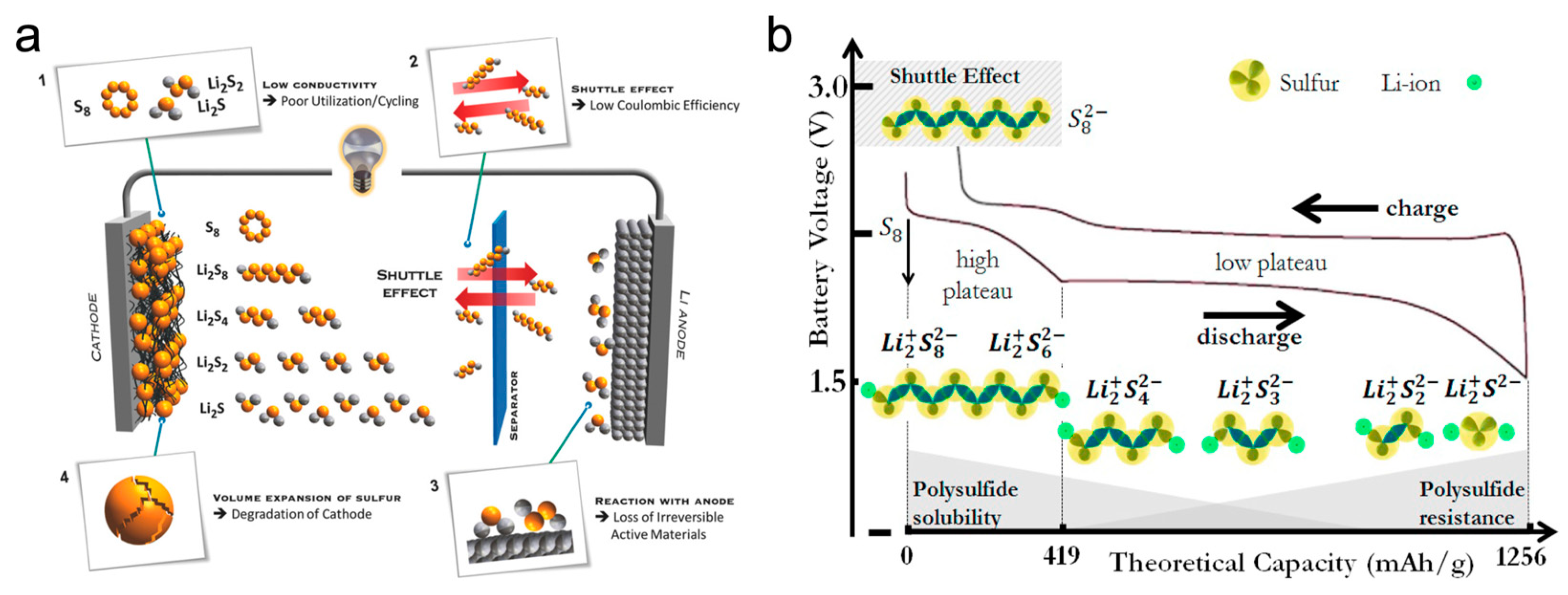
:1. Introduction

2. Discussion
2.1. Application in Cathode
2.2. Application in Anode
2.3. Application in Separator
2.4. Application in Electrolyte
3. Conclusions and Perspectives
Author Contributions
Funding
Institutional Review Board Statement
Data Availability Statement
Acknowledgments
Conflicts of Interest
References
- Awuzie, C.I. Conducting Polymers. Mater. Today Proc. 2017, 4, 5721–5726. [Google Scholar] [CrossRef]
- Guimard, N.K.; Gomez, N.; Schmidt, C.E. Conducting polymers in biomedical engineering. Prog. Polym. Sci. 2007, 32, 876–921. [Google Scholar] [CrossRef]
- Swager, T.M. 50th Anniversary Perspective: Conducting/Semiconducting Conjugated Polymers. A Personal Perspective on the Past and the Future. Macromolecules 2017, 50, 4867–4886. [Google Scholar] [CrossRef]
- Shirakawa, H. The Discovery of Polyacetylene Film: The Dawning of an Era of Conducting Polymers (Nobel Lecture). Angew. Chem. Int. Ed. 2001, 40, 2574–2580. [Google Scholar] [CrossRef]
- Ensafi, A.A.; Mousaabadi, K.Z.; Fazel-Zarandi, R. Application of Conductive Polymers in Electrochemistry. In Conductive Polymers in Analytical Chemistry; ACS Symposium Series; American Chemical Society: Washington, DC, USA, 2022; Volume 1405, pp. 185–217. [Google Scholar]
- Namsheer, K.; Rout, C.S. Conducting polymers: A comprehensive review on recent advances in synthesis, properties and applications. RSC Adv. 2021, 11, 5659–5697. [Google Scholar] [CrossRef]
- Kumar, R.; Singh, S.; Yadav, B. Conducting polymers: Synthesis, properties and applications. Int. Adv. Res. J. Sci. Eng. Technol. 2015, 2, 110–124. [Google Scholar]
- Fomo, G.; Waryo, T.; Feleni, U.; Baker, P.; Iwuoha, E. Electrochemical Polymerization. In Functional Polymers; Jafar Mazumder, M.A., Sheardown, H., Al-Ahmed, A., Eds.; Springer International Publishing: Cham, Switzerland, 2019; pp. 105–131. [Google Scholar]
- Sadki, S.; Schottland, P.; Brodie, N.; Sabouraud, G. The mechanisms of pyrrole electropolymerization. Chem. Soc. Rev. 2000, 29, 283–293. [Google Scholar] [CrossRef]
- Castro-Beltran, A.; Alvarado-Beltran, C.G.; Lara-Sanchez, J.F.; de la Cruz, W.; Castillon-Barraza, F.F.; Cruz-Silva, R. Electrochemical Deposition of Polypyrrole in the Presence of Silanes as Adhesion Promoters. Polymers 2023, 15, 2354. [Google Scholar] [CrossRef]
- Kim, S.; Cho, M.; Lee, Y. Point-of-Care Platform for Early Diagnosis of Parkinson’s Disease. ACS Appl. Bio Mater. 2020, 3, 8997–9001. [Google Scholar] [CrossRef]
- Zhao, M.; Li, B.-Q.; Zhang, X.-Q.; Huang, J.-Q.; Zhang, Q. A Perspective toward Practical Lithium–Sulfur Batteries. ACS Cent. Sci. 2020, 6, 1095–1104. [Google Scholar] [CrossRef]
- Kim, S.; Cho, M.; Chanthad, C.; Lee, Y. New redox-mediating polymer binder for enhancing performance of Li-S batteries. J. Energy Chem. 2020, 44, 154–161. [Google Scholar] [CrossRef] [Green Version]
- Kim, S.; Cho, M.; Lee, Y. Saponin-containing multifunctional binder toward superior long-term cycling stability in Li–S batteries. J. Mater. Chem. A 2020, 8, 10419–10425. [Google Scholar] [CrossRef]
- Yoo, G.; Kim, S.; Chanthad, C.; Cho, M.; Lee, Y. Elastic rubber-containing multifunctional binder for advanced Li-S batteries. Chem. Eng. J. 2021, 405, 126628. [Google Scholar] [CrossRef]
- Zhang, J.; Huang, H.; Bae, J.; Chung, S.-H.; Zhang, W.; Manthiram, A.; Yu, G. Nanostructured Host Materials for Trapping Sulfur in Rechargeable Li–S Batteries: Structure Design and Interfacial Chemistry. Small Methods 2018, 2, 1700279. [Google Scholar] [CrossRef]
- Propp, K.; Marinescu, M.; Auger, D.J.; O’Neill, L.; Fotouhi, A.; Somasundaram, K.; Offer, G.J.; Minton, G.; Longo, S.; Wild, M.; et al. Multi-temperature state-dependent equivalent circuit discharge model for lithium-sulfur batteries. J. Power Sources 2016, 328, 289–299. [Google Scholar] [CrossRef] [Green Version]
- Alex, A.; Singha, N.K.; Choudhury, S. Exploring inverse vulcanization in lithium–sulfur batteries. Curr. Opin. Electrochem. 2023, 39, 101271. [Google Scholar] [CrossRef]
- Nakamura, N.; Ahn, S.; Momma, T.; Osaka, T. Future potential for lithium-sulfur batteries. J. Power Sources 2023, 558, 232566. [Google Scholar] [CrossRef]
- Rosenman, A.; Markevich, E.; Salitra, G.; Aurbach, D.; Garsuch, A.; Chesneau, F.F. Review on Li-Sulfur Battery Systems: An Integral Perspective. Adv. Energy Mater. 2015, 5, 1500212. [Google Scholar] [CrossRef]
- Liu, T.; Hu, H.; Ding, X.; Yuan, H.; Jin, C.; Nai, J.; Liu, Y.; Wang, Y.; Wan, Y.; Tao, X. 12 years roadmap of the sulfur cathode for lithium sulfur batteries (2009–2020). Energy Storage Mater. 2020, 30, 346–366. [Google Scholar] [CrossRef]
- Kim, S.; Kim, J.; Kim, M.; Cho, M.; Lee, Y. Aqua-processable carbon quantum dot–assisted resilient polymer binder for advanced lithium-sulfur batteries. Int. J. Energy Res. 2021, 45, 21050–21057. [Google Scholar] [CrossRef]
- Liang, Y.; Zhao, C.-Z.; Yuan, H.; Chen, Y.; Zhang, W.; Huang, J.-Q.; Yu, D.; Liu, Y.; Titirici, M.-M.; Chueh, Y.-L.; et al. A review of rechargeable batteries for portable electronic devices. InfoMat 2019, 1, 6–32. [Google Scholar] [CrossRef] [Green Version]
- Liu, J.; Wang, M.; Xu, N.; Qian, T.; Yan, C. Progress and perspective of organosulfur polymers as cathode materials for advanced lithium-sulfur batteries. Energy Storage Mater. 2018, 15, 53–64. [Google Scholar] [CrossRef]
- Ning, J.; Yu, H.; Mei, S.; Schütze, Y.; Risse, S.; Kardjilov, N.; Hilger, A.; Manke, I.; Bande, A.; Ruiz, V.G.; et al. Constructing Binder- and Carbon Additive-Free Organosulfur Cathodes Based on Conducting Thiol-Polymers through Electropolymerization for Lithium-Sulfur Batteries. ChemSusChem 2022, 15, e202200434. [Google Scholar] [CrossRef]
- Schütze, Y.; Gayen, D.; Palczynski, K.; de Oliveira Silva, R.; Lu, Y.; Tovar, M.; Partovi-Azar, P.; Bande, A.; Dzubiella, J. How Regiochemistry Influences Aggregation Behavior and Charge Transport in Conjugated Organosulfur Polymer Cathodes for Lithium–Sulfur Batteries. ACS Nano 2023, 17, 7889–7900. [Google Scholar] [CrossRef] [PubMed]
- Ramezanitaghartapeh, M.; Hollenkamp, A.F.; Musameh, M.; Mahon, P.J. High capacity polycarbazole-sulfur cathode for use in lithium-sulfur batteries. Electrochim. Acta 2021, 391, 138898. [Google Scholar] [CrossRef]
- Xu, P.; Han, X.; Zhang, B.; Du, Y.; Wang, H.-L. Multifunctional polymer–metal nanocomposites via direct chemical reduction by conjugated polymers. Chem. Soc. Rev. 2014, 43, 1349–1360. [Google Scholar] [CrossRef] [PubMed]
- Kim, S.; Yang, X.; Cho, M.; Lee, Y. Nanostructured conductive polymer shield for highly reversible dendrite-free zinc metal anode. Chem. Eng. J. 2022, 427, 131954. [Google Scholar] [CrossRef]
- Contal, E.; Lakard, S.; Dumur, F.; Lakard, B. Investigation of polycarbazoles thin films prepared by electrochemical oxidation of 3- and 9-substituted carbazoles. Prog. Org. Coat. 2022, 162, 106563. [Google Scholar] [CrossRef]
- Kaiser, M.R.; Han, Z.; Wang, J. Electro-polymerized polypyrrole film for fabrication of flexible and slurry-free polypyrrole-sulfur-polypyrrole sandwich electrode for the lithium-sulfur battery. J. Power Sources 2019, 437, 226925. [Google Scholar] [CrossRef]
- Nakamura, N.; Yokoshima, T.; Nara, H.; Mikuriya, H.; Shiosaki, A.; Ahn, S.; Momma, T.; Osaka, T. Polypyrrole Modification of High Sulfur-Loaded Three-Dimensional Aluminum Foam Cathode in Lithium–Sulfur Batteries for High-Rate Capability. J. Electrochem. Soc. 2021, 168, 040517. [Google Scholar] [CrossRef]
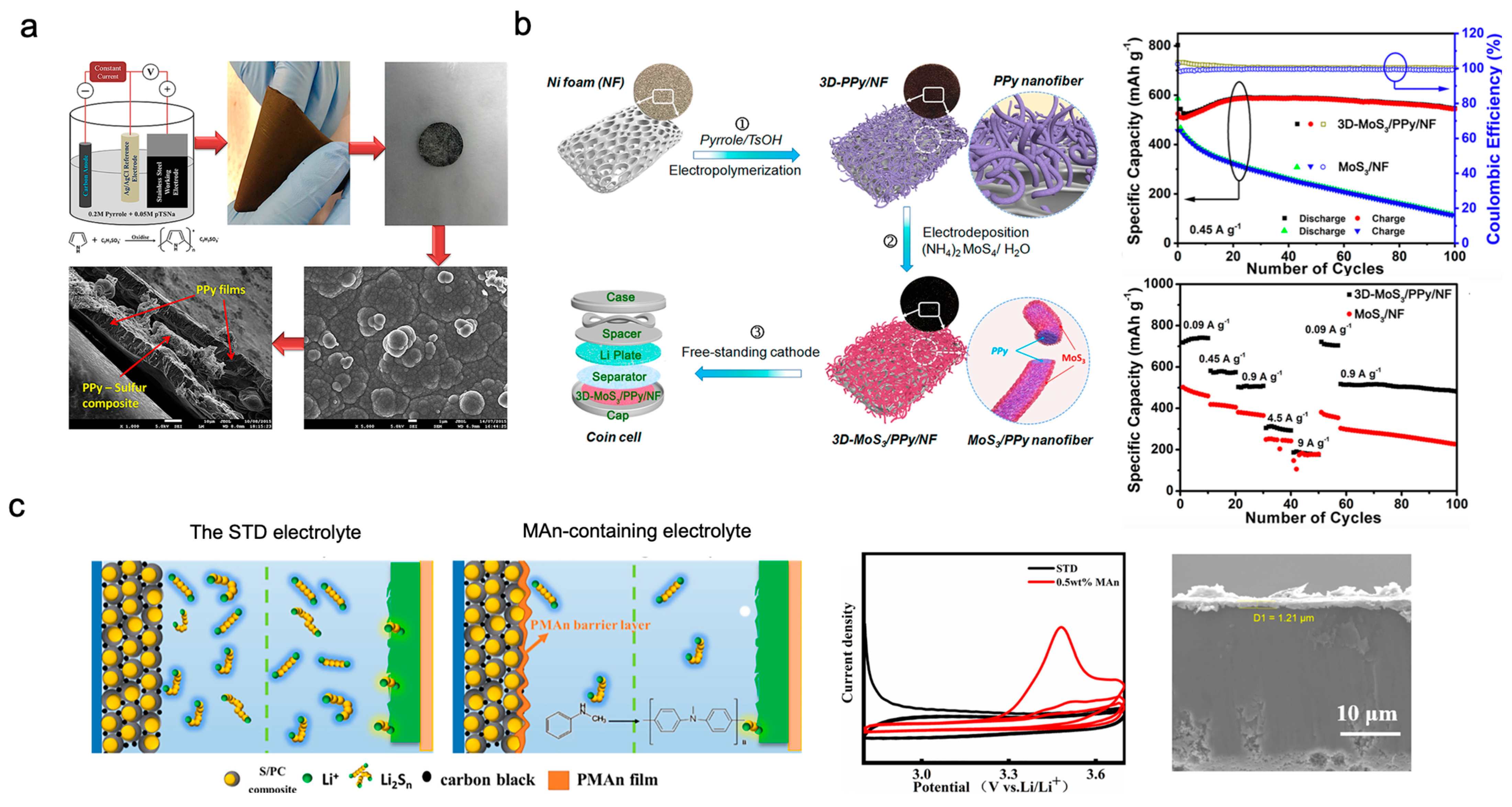
- Yu, H.; Siebert, A.; Mei, S.; Garcia-Diez, R.; Félix, R.; Quan, T.; Xu, Y.; Frisch, J.; Wilks, R.G.; Bär, M.; et al. Electrochemical Realization of 3D Interconnected MoS3/PPy Nanowire Frameworks as Sulfur-Equivalent Cathode Materials for Li-S Batteries. Energy Environ. Mater. 2022, e12539. [Google Scholar] [CrossRef]
- Shi, C.; Hong, B.; Zhang, X.; Xiang, Q.; Zhang, Z.; Zhang, K.; Fang, J.; Lai, Y. In-situ growth poly(N-methylaniline) coating on sulfur cathode for lithium-sulfur battery. J. Electroanal. Chem. 2020, 871, 114312. [Google Scholar] [CrossRef]
- Gao, X.; Guo, C.; Ma, Z.; Xi, G.; Meng, Y.; Li, Y. Boosting Li–S battery performance using an in-cell electropolymerized conductive polymer. Mater. Adv. 2021, 2, 974–984. [Google Scholar] [CrossRef]
- Liu, B.; Zhang, J.-G.; Xu, W. Advancing Lithium Metal Batteries. Joule 2018, 2, 833–845. [Google Scholar] [CrossRef] [Green Version]
- Yang, K.M.; Yang, K.; Cho, M.; Kim, S.; Lee, Y. Self-assembled functional layers onto separator toward practical lithium metal batteries. Chem. Eng. J. 2023, 454, 140191. [Google Scholar] [CrossRef]
- Liu, J.; Cao, Y.; Zhou, J.; Wang, M.; Chen, H.; Yang, T.; Sun, Y.; Qian, T.; Yan, C. Artificial Lithium Isopropyl-Sulfide Macromolecules as an Ion-Selective Interface for Long-Life Lithium–Sulfur Batteries. ACS Appl. Mater. Interfaces 2020, 12, 54537–54544. [Google Scholar] [CrossRef]
- Kim, S.; Kim, D.H.; Cho, M.; Lee, W.B.; Lee, Y. Fast-Charging Lithium–Sulfur Batteries Enabled via Lean Binder Content. Small 2020, 16, 2004372. [Google Scholar] [CrossRef]
- Huang, C.; Xiao, J.; Shao, Y.; Zheng, J.; Bennett, W.D.; Lu, D.; Saraf, L.V.; Engelhard, M.; Ji, L.; Zhang, J.; et al. Manipulating surface reactions in lithium–sulphur batteries using hybrid anode structures. Nat. Commun. 2014, 5, 3015. [Google Scholar] [CrossRef] [Green Version]
- Grotkopp, N.L.; Horst, M.; Batzer, M.; Garnweitner, G.; Jean-Fulcrand, A. Flexible Freestanding Thin Polyethylene Oxide-Based Film as Artificial Solid–Electrolyte Interface to Protect Lithium Metal in Lithium–Sulfur Batteries. Adv. Energy Sustain. Res. 2023, 4, 2200146. [Google Scholar] [CrossRef]
- Ma, T.; Ren, X.; Hu, L.; Teng, W.; Wang, X.; Wu, G.; Liu, J.; Nan, D.; Yu, X. Functional Polymer Materials for Advanced Lithium Metal Batteries: A Review and Perspective. Polymers 2022, 14, 3452. [Google Scholar]
- Teng, W.; Li, Y.; Ma, T.; Ren, X.; Nan, D.; Liu, J.; Wang, X.; Yang, Q.; Deng, J. Uniform Lithium Deposition Induced by ZnFx(OH)y for High-Performance Sulfurized Polyacrylonitrile-Based Lithium-Sulfur Batteries. Polymers 2022, 14, 4494. [Google Scholar] [CrossRef] [PubMed]
- Xiong, X.; Qiao, Q.; Zhou, Q.; Cheng, X.; Liu, L.; Fu, L.; Chen, Y.; Wang, B.; Wu, X.; Wu, Y. Constructing a lithiophilic polyaniline coating via in situ polymerization for dendrite-free lithium metal anode. Nano Res. 2023, 16, 8448–8456. [Google Scholar] [CrossRef]
- Zhang, J.; Zhou, M.; Shi, J.; Zhao, Y.; Wen, X.; Su, C.-C.; Wu, J.; Guo, J. Regulating lithium deposition via electropolymerization of acrylonitrile in rechargeable lithium metal batteries. Nano Energy 2021, 88, 106298. [Google Scholar] [CrossRef]
- Huang, X. Separator technologies for lithium-ion batteries. J. Solid State Electrochem. 2011, 15, 649–662. [Google Scholar] [CrossRef]
- Kim, S.; Shirvani-Arani, S.; Choi, S.; Cho, M.; Lee, Y. Strongly Anchoring Polysulfides by Hierarchical Fe3O4/C3N4 Nanostructures for Advanced Lithium–Sulfur Batteries. Nano-Micro Lett. 2020, 12, 139. [Google Scholar] [CrossRef] [PubMed]
- Kim, S.; Kim, D.H.; Cho, M.; Lee, W.B.; Lee, Y. Long-life lithium–sulfur battery enabled by a multifunctional gallium oxide shield. Chem. Eng. J. 2021, 420, 129772. [Google Scholar] [CrossRef]
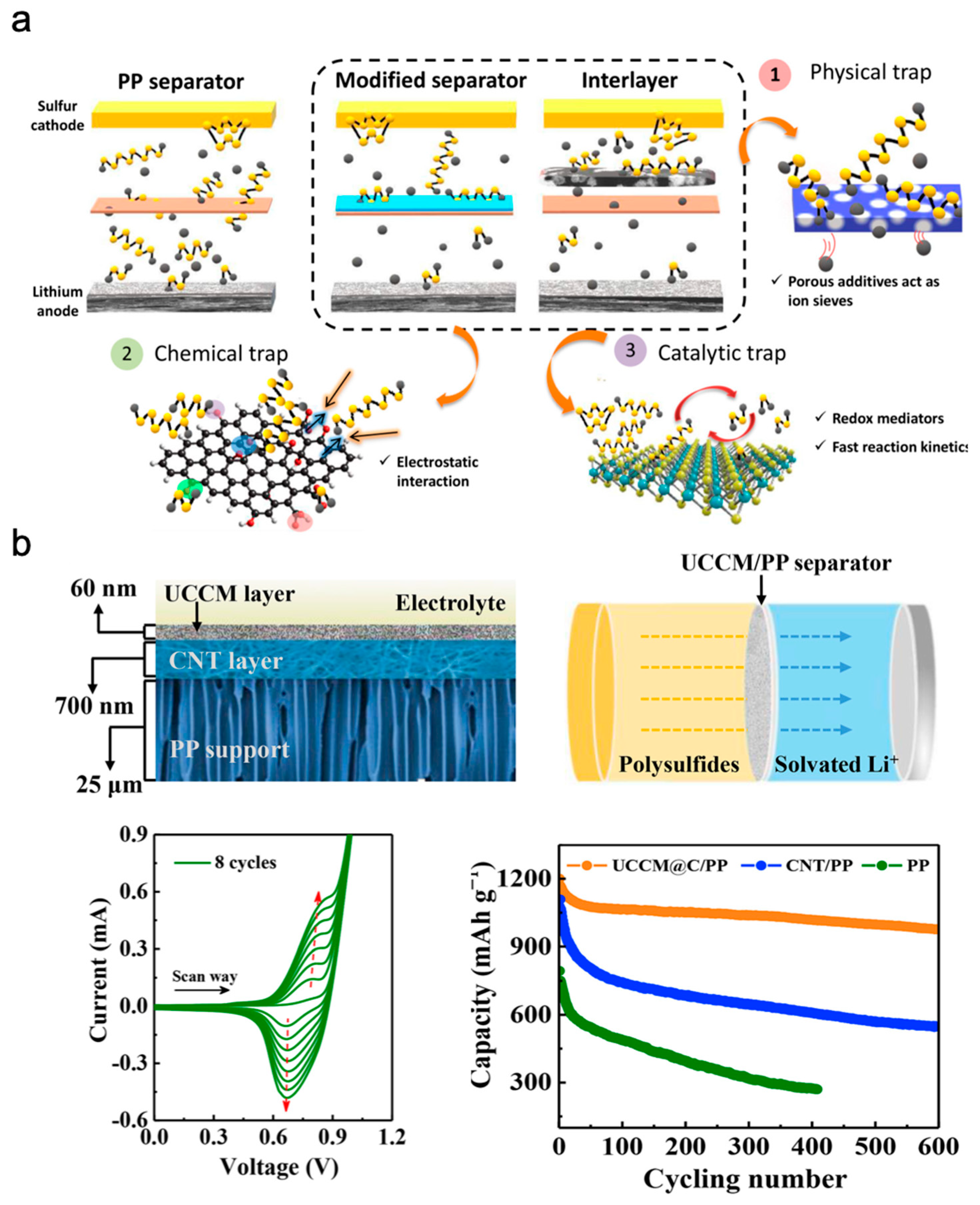
- Fan, L.; Li, M.; Li, X.; Xiao, W.; Chen, Z.; Lu, J. Interlayer Material Selection for Lithium-Sulfur Batteries. Joule 2019, 3, 361–386. [Google Scholar] [CrossRef] [Green Version]
- Su, Y.-S.; Manthiram, A. A new approach to improve cycle performance of rechargeable lithium–sulfur batteries by inserting a free-standing MWCNT interlayer. Chem. Commun. 2012, 48, 8817–8819. [Google Scholar] [CrossRef] [Green Version]
- Suriyakumar, S.; Stephan, A.M. Mitigation of Polysulfide Shuttling by Interlayer/Permselective Separators in Lithium–Sulfur Batteries. ACS Appl. Energy Mater. 2020, 3, 8095–8129. [Google Scholar] [CrossRef]
- Deimede, V.; Elmasides, C. Separators for Lithium-Ion Batteries: A Review on the Production Processes and Recent Developments. Energy Technol. 2015, 3, 453–468. [Google Scholar] [CrossRef]
- Guo, D.; Li, X.; Ming, F.; Zhou, Z.; Liu, H.; Hedhili, M.N.; Tung, V.; Alshareef, H.N.; Li, Y.; Lai, Z. Electropolymerization growth of an ultrathin, compact, conductive and microporous (UCCM) polycarbazole membrane for high energy Li–S batteries. Nano Energy 2020, 73, 104769. [Google Scholar] [CrossRef]
- Qin, J.; Kim, S.; Cho, M.; Lee, Y. Hierarchical and ultra-sensitive amyloid beta oligomer sensor for practical applications. Chem. Eng. J. 2020, 401, 126055. [Google Scholar] [CrossRef]
- Yang, K.M.; Kim, S.; Yang, K.; Choi, S.; Cho, M.; Lee, Y. Ultra-Stable Lithium-Sulfur Batteries Using Nickel Phosphide@Carbon Fabric Interlayer. J. Electrochem. Soc. 2021, 168, 120513. [Google Scholar] [CrossRef]
- Yang, K.; Chen, J.; Kim, S.; Xiong, P.; Chen, W.; Cho, M.; Lee, Y. Achieving Fast and Reversible Sulfur Redox by Proper Interaction of Electrolyte in Potassium Batteries. ACS Energy Lett. 2023, 8, 2169–2176. [Google Scholar] [CrossRef]
- Kim, S.; Cho, M.; Lee, Y. High-Performance Li–Se Battery Enabled via a One-Piece Cathode Design. Adv. Energy Mater. 2020, 10, 1903477. [Google Scholar] [CrossRef]
- Zhang, B.; Wu, J.; Gu, J.; Li, S.; Yan, T.; Gao, X.-P. The Fundamental Understanding of Lithium Polysulfides in Ether-Based Electrolyte for Lithium–Sulfur Batteries. ACS Energy Lett. 2021, 6, 537–546. [Google Scholar] [CrossRef]
- Lin, Z.; Liu, Z.; Fu, W.; Dudney, N.J.; Liang, C. Phosphorous Pentasulfide as a Novel Additive for High-Performance Lithium-Sulfur Batteries. Adv. Funct. Mater. 2013, 23, 1064–1069. [Google Scholar] [CrossRef]
- Yang, K.; Kim, S.; Yang, X.; Cho, M.; Lee, Y. Binder-Free and High-Loading Cathode Realized by Hierarchical Structure for Potassium–Sulfur Batteries. Small Methods 2022, 6, 2100899. [Google Scholar] [CrossRef]
- Agostini, M.; Xiong, S.; Matic, A.; Hassoun, J. Polysulfide-containing Glyme-based Electrolytes for Lithium Sulfur Battery. Chem. Mater. 2015, 27, 4604–4611. [Google Scholar] [CrossRef]
- Lee, J.H.; Kim, S.; Cho, M.; Chanthad, C.; Lee, Y. Crosslinked Gel Polymer Electrolytes for Si Anodes in Li-Ion Batteries. J. Electrochem. Soc. 2019, 166, A2755. [Google Scholar] [CrossRef]
- Manthiram, A.; Yu, X.; Wang, S. Lithium battery chemistries enabled by solid-state electrolytes. Nat. Rev. Mater. 2017, 2, 16103. [Google Scholar] [CrossRef]
- Bonnick, P.; Muldoon, J. The Dr Jekyll and Mr Hyde of lithium sulfur batteries. Energy Environ. Sci. 2020, 13, 4808–4833. [Google Scholar] [CrossRef]
- Guo, W.; Zhang, W.; Si, Y.; Wang, D.; Fu, Y.; Manthiram, A. Artificial dual solid-electrolyte interfaces based on in situ organothiol transformation in lithium sulfur battery. Nat. Commun. 2021, 12, 3031. [Google Scholar] [CrossRef] [PubMed]
- Chen, J.; Lu, H.; Zhang, X.; Zhang, Y.; Yang, J.; Nuli, Y.; Huang, Y.; Wang, J. Electrochemical polymerization of nonflammable electrolyte enabling fast-charging lithium-sulfur battery. Energy Storage Mater. 2022, 50, 387–394. [Google Scholar] [CrossRef]
- Zhong, H.; Wang, C.; Xu, Z.; Ding, F.; Liu, X. A novel quasi-solid state electrolyte with highly effective polysulfide diffusion inhibition for lithium-sulfur batteries. Sci. Rep. 2016, 6, 25484. [Google Scholar] [CrossRef] [PubMed] [Green Version]
- Kim, S.; Cho, M.; Lee, Y. Multifunctional Chitosan–rGO Network Binder for Enhancing the Cycle Stability of Li–S Batteries. Adv. Funct. Mater. 2020, 30, 1907680. [Google Scholar] [CrossRef]
- Choi, S.; Kim, S.; Cho, M.; Lee, Y. Durable Conductive Webs as Multifunctional Binder for the High-Performance Lithium–Sulfur Battery. ACS Appl. Energy Mater. 2020, 3, 7825–7831. [Google Scholar] [CrossRef]
- Kim, S.; Yang, J.; Liu, D.; Huang, Y.; Lee, Y. Bio-Derived Materials Achieving High Performance in Alkali Metal–Chalcogen Batteries. Adv. Funct. Mater. 2021, 31, 2008354. [Google Scholar] [CrossRef]
- Liu, Y.; Meng, X.; Wang, Z.; Qiu, J. A Li2S-based all-solid-state battery with high energy and superior safety. Sci. Adv. 2022, 8, eabl8390. [Google Scholar] [CrossRef]
- Janek, J.; Zeier, W.G. Challenges in speeding up solid-state battery development. Nat. Energy 2023, 8, 230–240. [Google Scholar] [CrossRef]
- Kim, S.; Chart, Y.A.; Narayanan, S.; Pasta, M. Thin Solid Electrolyte Separators for Solid-State Lithium–Sulfur Batteries. Nano Lett. 2022, 22, 10176–10183. [Google Scholar] [CrossRef] [PubMed]
- Wang, H.; Chen, S.; Fu, C.; Ding, Y.; Liu, G.; Cao, Y.; Chen, Z. Recent Advances in Conversion-Type Electrode Materials for Post Lithium-Ion Batteries. ACS Mater. Lett. 2021, 3, 956–977. [Google Scholar] [CrossRef]
- Choi, S.; Kim, S.; Yang, K.; Cho, M.; Lee, Y. Highly Stable Potassium-Ion Battery Enabled by Nanoengineering of an Sb Anode. ACS Appl. Mater. Interfaces 2022, 14, 17175–17184. [Google Scholar] [CrossRef] [PubMed]
- Yu, S.-H.; Feng, X.; Zhang, N.; Seok, J.; Abruña, H.D. Understanding Conversion-Type Electrodes for Lithium Rechargeable Batteries. Acc. Chem. Res. 2018, 51, 273–281. [Google Scholar] [CrossRef]
- Xiao, A.W.; Galatolo, G.; Pasta, M. The case for fluoride-ion batteries. Joule 2021, 5, 2823–2844. [Google Scholar] [CrossRef]


Disclaimer/Publisher’s Note: The statements, opinions and data contained in all publications are solely those of the individual author(s) and contributor(s) and not of MDPI and/or the editor(s). MDPI and/or the editor(s) disclaim responsibility for any injury to people or property resulting from any ideas, methods, instructions or products referred to in the content. |
© 2023 by the authors. Licensee MDPI, Basel, Switzerland. This article is an open access article distributed under the terms and conditions of the Creative Commons Attribution (CC BY) license (https://creativecommons.org/licenses/by/4.0/).
Share and Cite
Kim, S.; Lee, Y. Electropolymerisation Technologies for Next-Generation Lithium–Sulphur Batteries. Polymers 2023, 15, 3231. https://doi.org/10.3390/polym15153231
Kim S, Lee Y. Electropolymerisation Technologies for Next-Generation Lithium–Sulphur Batteries. Polymers. 2023; 15(15):3231. https://doi.org/10.3390/polym15153231
Chicago/Turabian StyleKim, Soochan, and Youngkwan Lee. 2023. "Electropolymerisation Technologies for Next-Generation Lithium–Sulphur Batteries" Polymers 15, no. 15: 3231. https://doi.org/10.3390/polym15153231
APA StyleKim, S., & Lee, Y. (2023). Electropolymerisation Technologies for Next-Generation Lithium–Sulphur Batteries. Polymers, 15(15), 3231. https://doi.org/10.3390/polym15153231