
Development and Characterisation of Sustainable Prepregs with Improved Fire Behaviour Based on Furan Resin and Basalt Fibre Reinforcement

 ,
,  and
and
Abstract
:1. Introduction
2. Materials and Methods
2.1. Materials
2.1.1. Furan Resin System
2.1.2. Basalt Fibre
2.1.3. Flame Retardants
2.2. Methods
2.2.1. Development and Characterisation of Resin Formulations
Selection of The Most Efficient Flame Retardant
DSC Characterisation of the Formulations
Fire Behaviour of The Formulations
- Calorimetric Cone
Study of the Effect of Flame-Retardant Concentration on the Viscosity of the Resin Formulation
Study of the Effect of Flame-Retardant Concentration on the Fire Behaviour
2.2.2. Development and Characterisation of Sustainable Prepregs
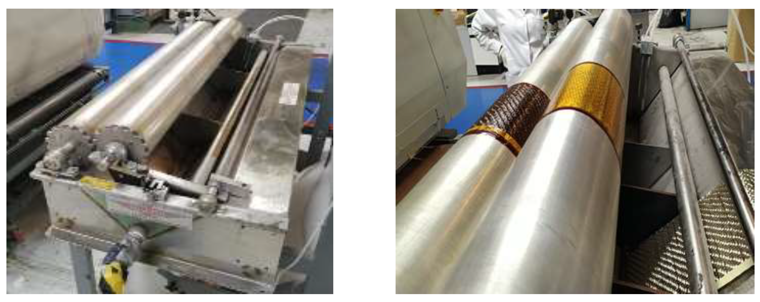
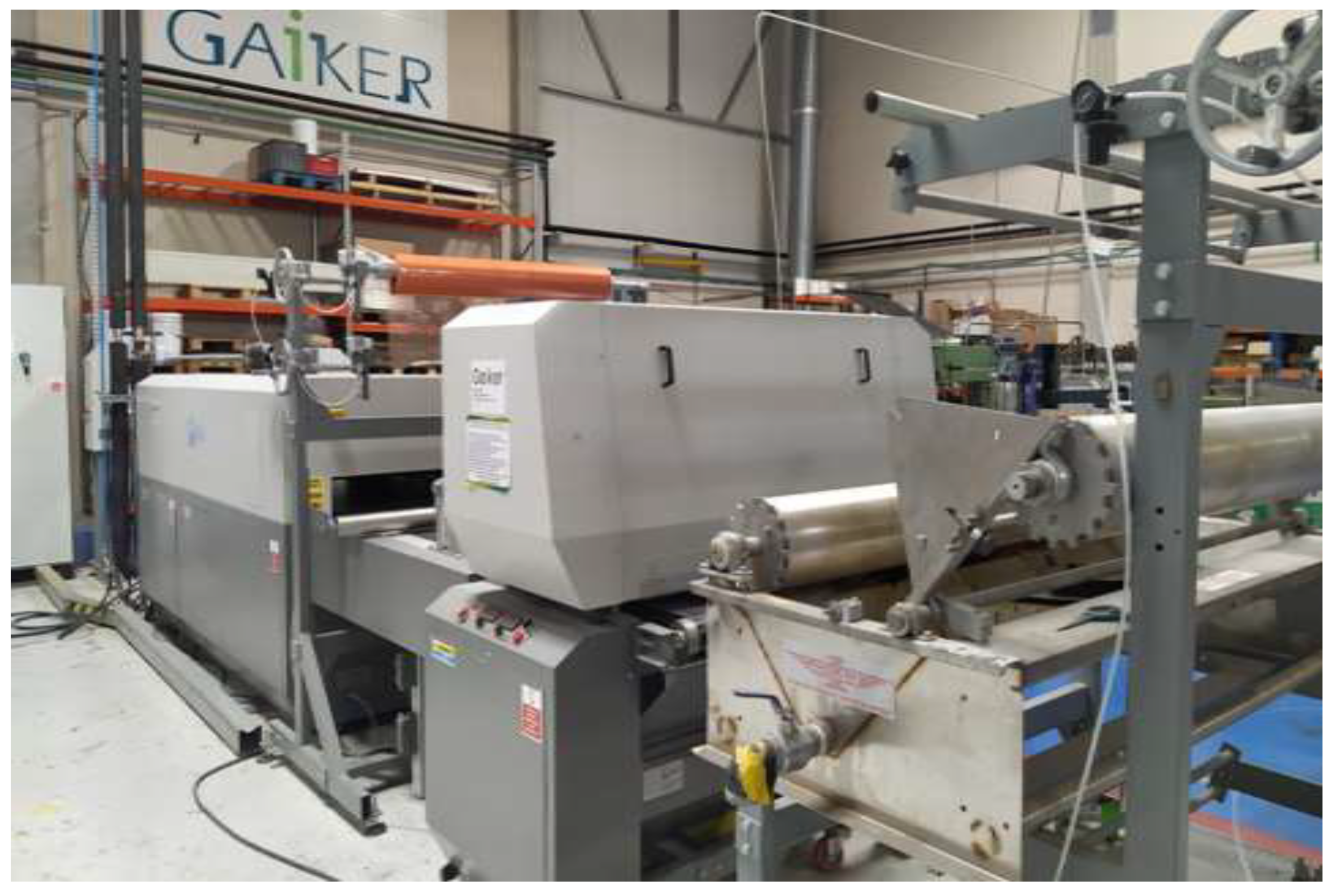
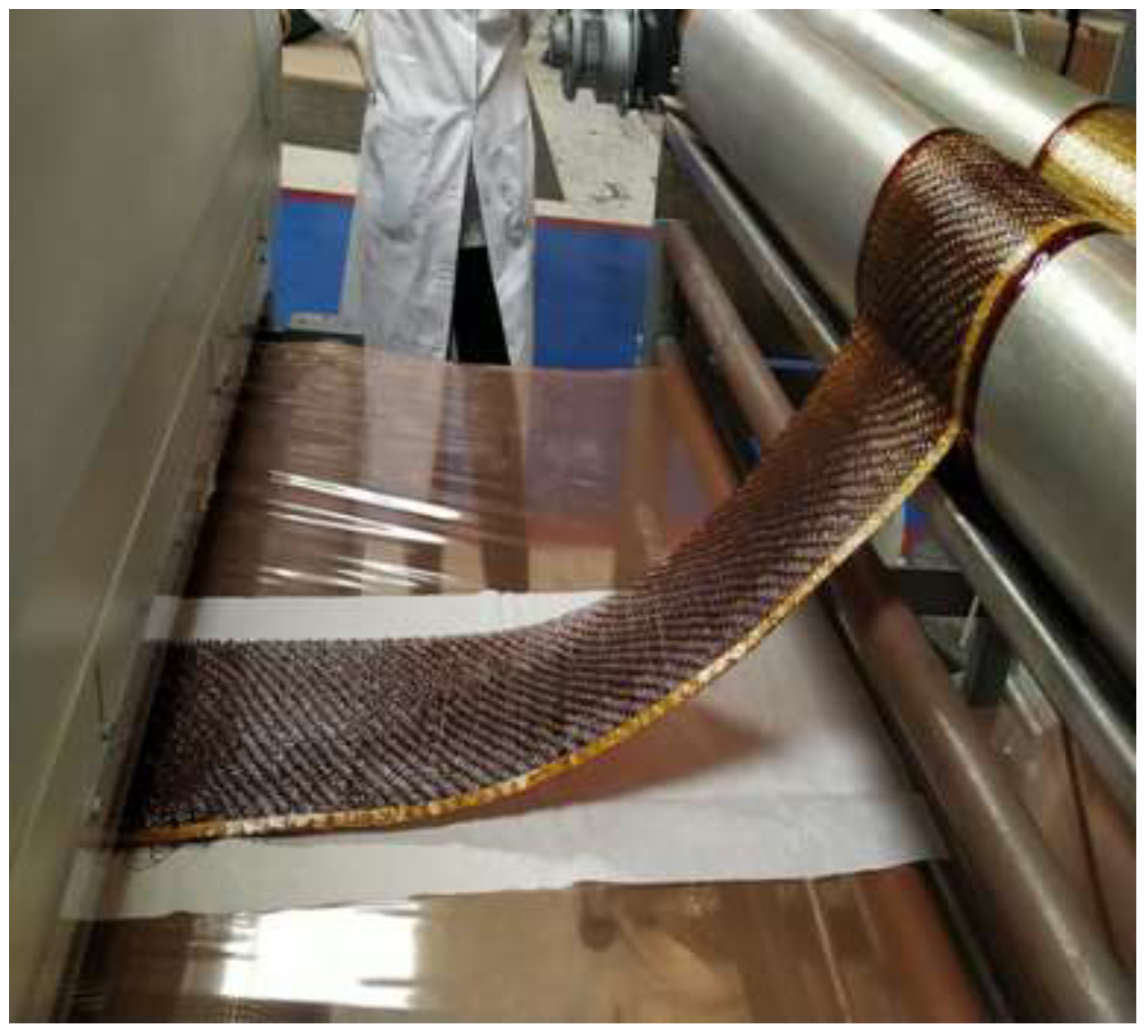
Manufacture and Processing of the Prepregs
Characterisation of Prepregs
- Calorimetric Cone
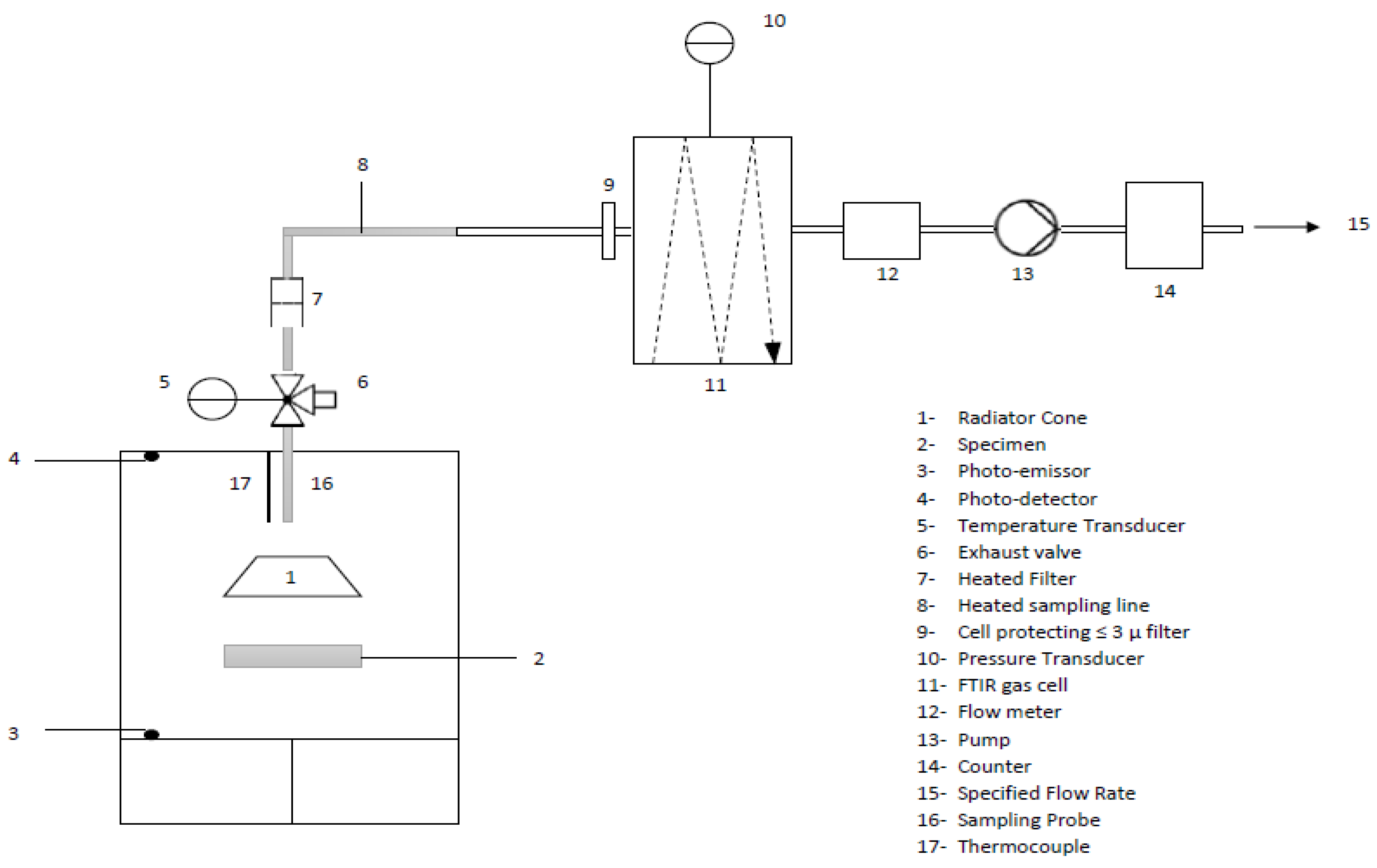
- Smoke Density and Gas Toxicity
- Pchamber: pressure of the chamber in Pa,
- Mgas: molar mass of the measured gas in kg/mol,
- R: gas constant (8.3143 J/molK),
- Cgas: volume fraction (dimensionless) of the measured gas by the FTIR in ppm,
- Tchamber: absolute temperature of the chamber at the FTIR sampling probe in K.
- Vertical Radiant Panel
3. Results and Discussion
3.1. Characterisation of the Resin Formulations with the Different Flame Retardants
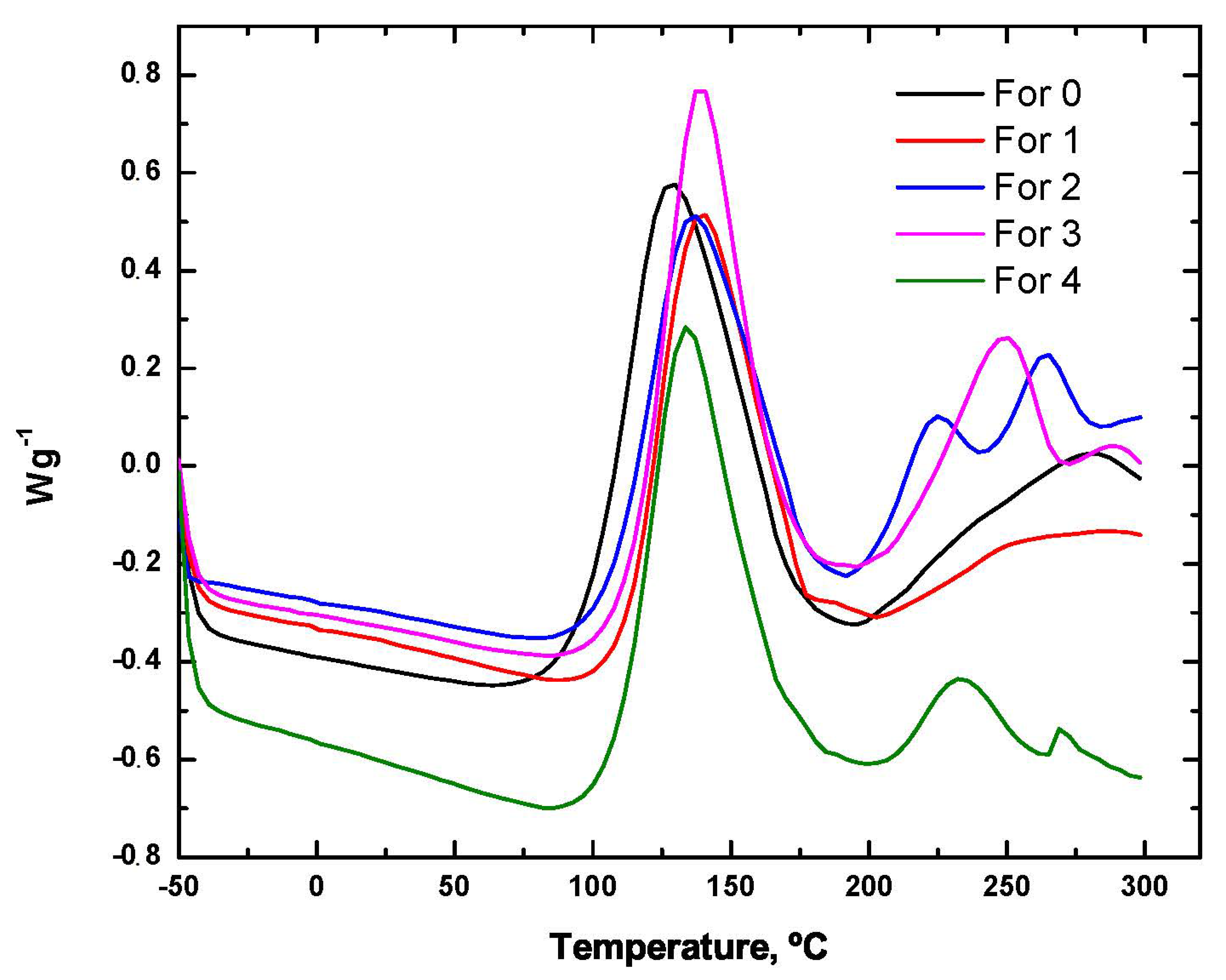
3.1.1. Differential Scanning Calorimetry (DSC)
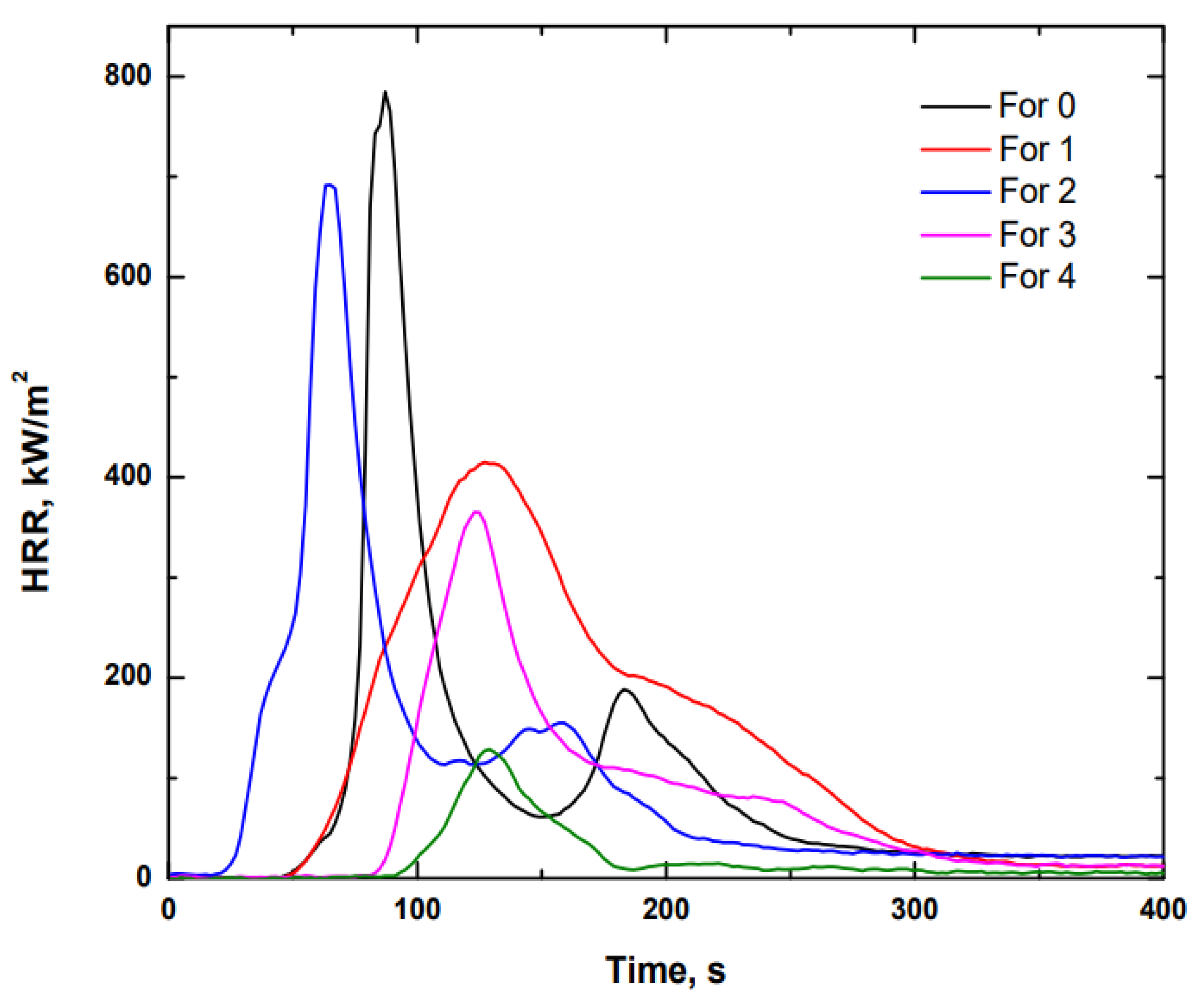
3.1.2. Calorimetric Cone
3.1.3. Viscosity
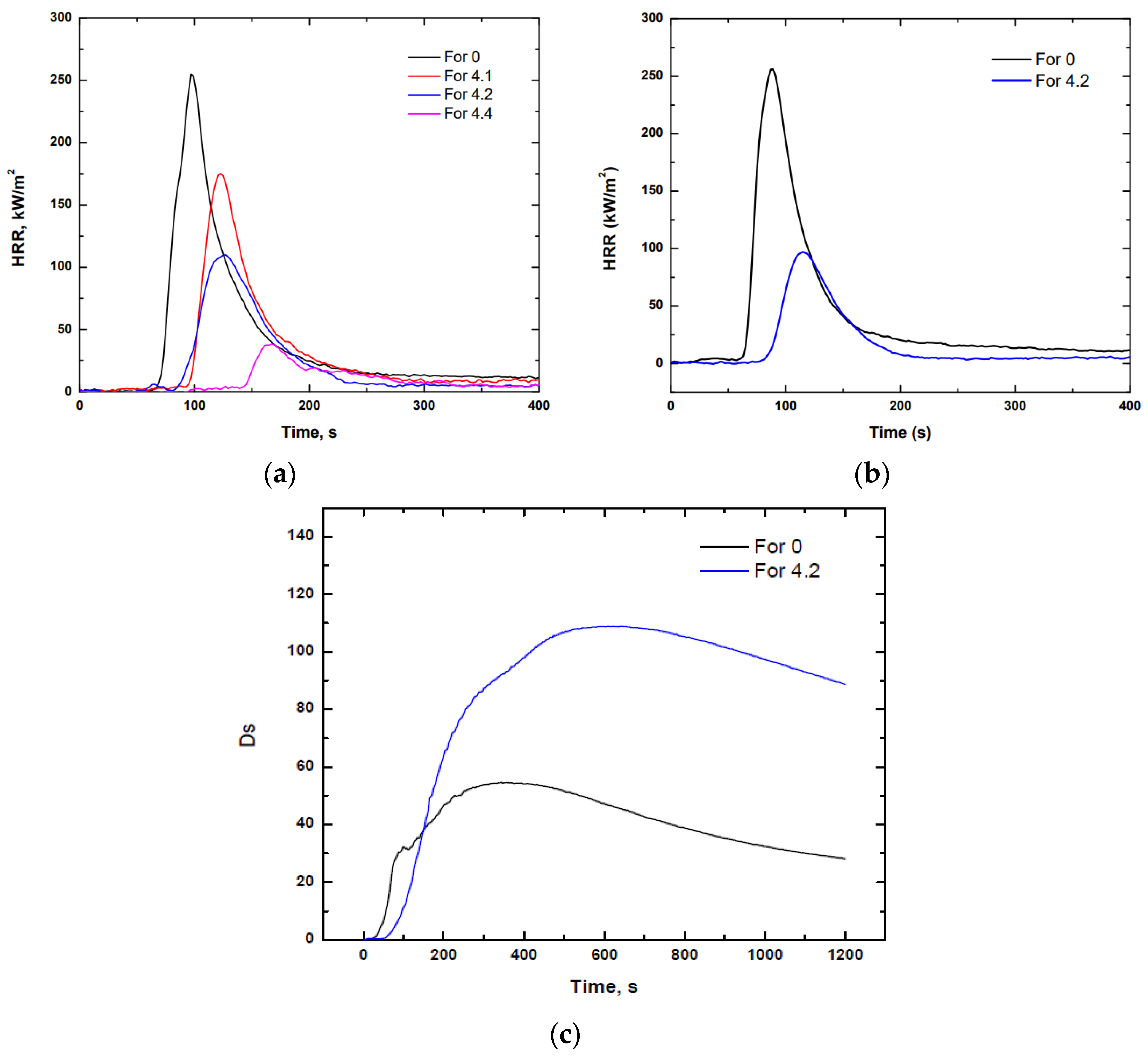
3.1.4. Calorimetric Cone
3.2. Prepreg Characterisation
3.2.1. Calorimetric Cone
3.2.2. Smoke Density and Gas Toxicity
3.2.3. Vertical Radiant Panel
4. Conclusions
- Flame-retarded material: R1HL3
- Reference material (non-flame-retarded material): R1HL2
Author Contributions
Funding
Institutional Review Board Statement
Informed Consent Statement
Data Availability Statement
Conflicts of Interest
References
- Aly, N.M. A review on utilization of textile composites in transportation towards sustainability. IOP Conf. Ser. Mater. Sci. Eng. 2017, 254, 042002. [Google Scholar] [CrossRef] [Green Version]
- Das, O.; Babu, K.; Shanmugam, V.; Sykam, K.; Tebyetekerwa, M.; Neisiany, R.E.; Försth, M.; Sas, G.; Gonzalez-Libreros, J.; Capezza, A.J.; et al. Natural and industrial wastes for sustainable and renewable polymer composites. Renew. Sustain. Energy Rev. 2022, 158, 112054. [Google Scholar] [CrossRef]
- Islam, S.; Islam, S.; Hasan, M. Natural Fiber Reinforced Polymer Composites as Sustainable Green Composites. Ref. Modul. Mater. Sci. Mater. Eng. 2022. [Google Scholar] [CrossRef]
- Andrew, J.J.; Dhakal, H. Sustainable biobased composites for advanced applications: Recent trends and future opportunities – A critical review. Compos. Part C Open Access 2021, 7, 100220. [Google Scholar] [CrossRef]
- Mohanty, A.K.; Vivekanandhan, S.; Pin, J.-M.; Misra, M. Composites from renewable and sustainable resources: Challenges and innovations. Science 2018, 362, 536–542. [Google Scholar] [CrossRef] [PubMed] [Green Version]
- Nicolais, L.; Bellucci, F.; Camino, G. Flammability of Polymer Composites. In Wiley Encyclopedia of Composites; Wiley: Alessandria, Italy, 2012. [Google Scholar] [CrossRef]
- Weil, E.D.; Levchik, S.V. Flame Retardants for Plastics and Textiles; Hanser: Munich, Germany, 2009. [Google Scholar]
- Troitzch, J. Plastics Flammability Handbook, 3rd ed.; Hanser: Munich, Germany, 2004. [Google Scholar]
- McKillip, W. ACS Symposium Series, Adhesives from Renewable Resources, Chapter 29, Chemistry of Furan Polymers 385; American Chemical Society: Washington, DC, USA, 1989; p. 408. [Google Scholar]
- Dunlop, A.P.; Peters, F.N. The Furans; Reinhold: New York, NY, USA, 1953. [Google Scholar]
- Monti, M.; Hoydonckx, H.; Stappers, F.; Camino, G. Thermal and combustion behavior of furan resin/silica nanocomposites. Eur. Polym. J. 2015, 67, 561–569. [Google Scholar] [CrossRef]
- Lopez de Vergara, U.; Sarrionandia, M.; Gondra, K.; Aurrekoetxea, J. Polymerization and curing kinetics of furan resins under conventional and microwave heating. Thermochim. Acta 2014, 581, 92–99. [Google Scholar] [CrossRef]
- de Vergara, U.L.; Sarrionandia, M.; Gondra, K.; Aurrekoetxea, J. Impact behaviour of basalt fibre reinforced furan composites cured under microwave and thermal conditions. Compos. Part B Eng. 2014, 66, 156–161. [Google Scholar] [CrossRef]
- Gómez Estévez, A.; Pérez Bermúdez, I.; Cordobés Herrera, M.; Garrido Carralero, N.; Lorenzo Maiquez, M.; Ramos, I. Introduction of R&D Results. Furanic Resin Plant. 2018. Available online: https://www.atamexico.com.mx/wp-content/uploads/2018/04/02.DERIVADOS-CUBA.pdf (accessed on 30 March 2022).
- Osuna Esteban, S. Study of the Surface Energy of Organic Matrices by Inverse Gas Chromatography for Its Application in the Development of Composite Materials; University of Alcalá. 2010. Available online: https://ebuah.uah.es/xmlui/handle/10017/8739 (accessed on 30 March 2022).
- Navarro Muedra, A. Influence of the Curing Cycle on the Shear Characteristics of High Grammage Composites with Vinyl-Urethane Resins. University of Valencia. 2002. Available online: https://riunet.upv.es/handle/10251/29959 (accessed on 30 March 2022).
- Czigány, T. Trends in fiber reinforcements—The future belongs to basalt fiber. Express Polym. Lett. 2007, 1, 59. [Google Scholar] [CrossRef]
- Czigány, T. Basalt Fiber Reinforced Hybrid Polymer Composites. Mater. Sci. Forum 2005, 473-474, 59–64. [Google Scholar] [CrossRef]
- Liu, Q.; Shaw, M.T.; McDonnell, A.M.; Parnas, R.S. Investigation of basalt fiber composites mechanical properties for application in transportation. PolymCompos 2006, 27, 41–48. [Google Scholar] [CrossRef]
- Zhou, Y.; Wang, H.; Bi, H.; Liu, X.; Gou, Q. Heat release rate of high-speed train fire in railway tunnels. Tunn. Undergr. Space Technol. 2020, 105. [Google Scholar] [CrossRef]
- AENOR. Standard UNE-EN 45545-2:2013+A1:2016. 2016. Available online: https://tienda.aenor.com/norma-une-en-45545-2-2013-a1-2016-n0056018 (accessed on 30 March 2022).
- Khalili, P.; Liu, X.; Tshai, K.Y.; Rudd, C.; Yi, X.; Kong, I. Development of fire retardancy of natural fiber composite encouraged by a synergy between zinc borate and ammonium polyphosphate. Compos. Part B Eng. 2018, 159, 165–172. [Google Scholar] [CrossRef]
- Sangregorio, A.; Muralidhara, A.; Guigo, N.; Marlair, G.; de Jong, E.; Sbirrazzuoli, N. Natural fibre composites with furanic thermoset resins. Comparison between polyfurfuryl alcohol and humins from sugar conversion. Compos. Part C Open Access 2021, 4. [Google Scholar] [CrossRef]
- Yu, Z.-R.; Mao, M.; Li, S.-N.; Xia, Q.-Q.; Cao, C.-F.; Zhao, L.; Zhang, G.-D.; Zheng, Z.-J.; Gao, J.-F.; Tang, L.-C. Facile and green synthesis of mechanically flexible and flame-retardant clay/graphene oxide nanoribbon interconnected networks for fire safety and prevention. Chem. Eng. J. 2020, 405, 126620. [Google Scholar] [CrossRef]
- Xiao, Y.; Ma, C.; Jin, Z.; Wang, J.; He, L.; Mu, X.; Song, L.; Hu, Y. Functional covalent organic framework for exceptional Fe2+, Co2+ and Ni2+ removal: An upcycling strategy to achieve water decontamination and reutilization as smoke suppressant and flame retardant simultaneously. Chem. Eng. J. 2020, 421, 127837. [Google Scholar] [CrossRef]
- Lim, K.-S.; Bee, S.-T.; Sin, L.T.; Tee, T.-T.; Ratnam, C.T.; Hui, D.; Rahmat, A.R. A review of application of ammonium polyphosphate as intumescent flame retardant in thermoplastic composites. Compos. Part B Eng. 2016, 84, 155–174. [Google Scholar] [CrossRef]


| Property | FL | FAM |
|---|---|---|
| Density (kg/m3) | 1210–1230 | 1160–1170 |
| Viscosity (cP) | 5000–10,000 | 2000–3000 |
| Dry weight (%) | 75–85 | 70–75 |
| Gel time (s) | 5–15 | 5–12 |
| Pot life (min) | - | 40–50 |
| Property | Epoxy | Polyester | Phenol | Furan |
|---|---|---|---|---|
| Density (kg/m3) | 1200–1250 | 1170–1260 | 1250 | 1160–1230 |
| Tensile strength (MPa) | 48–90 | 40 | 32.8–36.2 | 29.2–39.4 |
| Tensile modulus (MPa) | 3100–3800 | 3100 | 2480–2500 | 2840–3000 |
| Elongation at break (%) | 1.5–8 | <3 | 1.4–1.5 | 1.2–1.9 |
| Property | Basalt | E-Glass | S-Glass | Carbon | Aramid |
|---|---|---|---|---|---|
| Density (g/cm3) | 2.65–2.80 | 2.50–2.60 | 2.46–2.54 | 1.75–1.95 | 1.45 |
| Diameter (µm) | 6–17 | 7–13 | - | 7–9 | - |
| Tensile strength (MPa) | 3000–4840 | 3100–3800 | 4020–4650 | 2500–6000 | 2900–3400 |
| Elasticity modulus (GPa) | 80–150 | 63–78 | 83–86 | 230–650 | 70–185 |
| Elongation at break (%) | 3.1–3.3 | 2.5–4.7 | 5.3–5.6 | 0.5–2.0 | 2.8–3.6 |
| Max. service temperature (°C) | 650–980 | 350–650 | 300–500 | 400–500 | 250 |
| Melting temperature (°C) | 1450 | 1120 | 1550 | - | - |
| Mass loss (%) after 3 h immersed in: | |||||
| H2O | 0.2 | 0.6 | 0.6 | - | - |
| 2N NaOH | 5 | 6 | 5 | - | - |
| 2N HCl | 2.2 | 38.9 | 15.7 | - | - |
| Requirement Set (Relevant Product No.) | Test Method Reference | Parameter and Unit | Maximum or Minimum | HL1 | HL2 | HL3 |
|---|---|---|---|---|---|---|
| R1 (IN1A; IN1B; IN1D; IN1E; IN4; IN5; IN6A; IN7; IN8; IN9B; IN11; IN12A; IN12B; IN14; F5) | T02 ISO 5658-2 | CFE, kW/m2 | Min. | 20 | 20 | 20 |
| T03.01 ISO 5660-1:50 kW/m2 | MARHE, kW/m2 | Max. | - | 90 | 60 | |
| T10.01 EN ISO 5659-2:50 kW/m2 | Ds (4) | Max. | 600 | 300 | 150 | |
| T10.02 EN ISO 5659-2:50 kW/m2 | VOF4, min | Max. | 1200 | 600 | 300 | |
| T11.01 EN ISO 5659-2:50 kW/m2 | CITG | Max. | 1.2 | 0.9 | 0.75 |
| Property | Value |
|---|---|
| Water content (wt.%) | 5.5 |
| Viscosity (25 °C, cP) | 4400 |
| pH | 5.1 |
| Property | Value |
|---|---|
| Density (g/cm3) | 2.67 |
| Range of work temperature (°C) | −250–650 |
| Monofilament diameter (µm) | 10–13 |
| Humidity Content (wt.%) | <0.5 |
| Specific tensile strength (mN/tex) | >650 |
| Grammage (g/cm2) | 600 |
| Watp (F/10 cm) | 25 |
| Weft (F/10 cm) | 25 |
| Thickness (mm) | 0.6 |
| Property | Value |
|---|---|
| Appearance | Clear, colourless liquid |
| Phosphorus content (%) | 17 |
| TEP content (%) | Min. 99.5 |
| Acid value (mg KOH/g) | Max. 0.05 |
| Water content (%) | Max. 0.2 |
| Hazen colour value | Max. 20 |
| Refractive index 20 °C | 1.405–1.407 |
| Density at 20 °C (g/cm3) | 1.065–1.074 |
| Viscosity at 20 °C (mPas) | 1.7 |
| Property | Value |
|---|---|
| Appearance | White powder |
| Phosphorus content (%) | 23.3–24 |
| Water content (%) | Max. 0.2 |
| Density at 20 °C (g/cm3) | 1.35 |
| Bulk density (kg/m3) | 400–600 |
| Decomposition temperature (°C) | >300 |
| Average particle size (D50) (µm) | 20–40 |
| Property | Value |
|---|---|
| Appearance | Fine, white powder |
| P2O5 content (%) | 72 |
| N content (%) | 14 |
| Specific gravity (g/cm3) | 1.95 |
| pH (10% in water) | 5.5 |
| Bulk density (g/cm3) | 0.6 |
| Solubility in water (g/100 cm3) | 0.8 |
| Oil absorption (g oil/100 g) | 27 |
| Decomposition temperature (°C) | 300 |
| Average particle size (D50) (µm) | 18 |
| Refuse at 45 µm (%) | 1 |
| Moisture (%) | 0.05 |
| Property | Value |
|---|---|
| Appearance | White powder |
| P2O5 content (%) | 31–35 |
| N content (%) | 40–44 |
| pH value (1% solution) | 5–6 |
| Decomposition temperature (°C) | >325 |
| Solubility (g/100 mL H2O) | <0.1 |
| Mean diameter (µm) | 8 |
| Component | For 0 | For 1 | For 2 | For 3 | For 4 |
|---|---|---|---|---|---|
| Furolite Resin 050915 A RF 2ST HV | 100 | 100 | 100 | 100 | 100 |
| Catalyst HM 1448 | 4 | 4 | 4 | 4 | 4 |
| Catalyst ATMP | 1 | 1 | 1 | 1 | 1 |
| Phosphinate Exolit OP1230 (powder) | - | 20 | - | - | - |
| Triethyl phosphate LEVAGARD TEPZ (liquid) | - | - | 20 | - | - |
| Melamine polyphosphate (MPP) BUDIT 3141 (powder) | - | - | - | 20 | - |
| Ammonium polyphosphate (APP) FR CROS484 (powder) | - | - | - | - | 20 |
| Component | For 0 | For 4.1 | For 4.2 | For 4.3 | For 4.4 |
|---|---|---|---|---|---|
| Furolite Resin 050915 A RF 2ST HV | 100 | 100 | 100 | 100 | 100 |
| Catalyst HM 1448 | 4 | 4 | 4 | 4 | 4 |
| Catalyst ATMP | 1 | 1 | 1 | 1 | 1 |
| Flame retardant, APP | - | 10 | 20 | 30 | 40 |
| Sample | Maximum Exotherm Temperature (°C) | Cure Enthalpy |
|---|---|---|
| For 0 | 128.42 | 272.52 |
| For 1 | 139.21 | 194.34 |
| For 2 | 136.04 | 198.30 |
| For 3 | 138.81 | 212.83 |
| For 4 | 133.96 | 205.81 |
| Formulation | Ignition Time (s) | Time to Extintion (s) | MARHE 1 (kW/m2) | THR 2 1200 s (MJ/m2) | Qmax. (kW/m2) | Average Mass Loss Rate (g/m2s) |
|---|---|---|---|---|---|---|
| 0 | 81 | >1200 | 169.7 | 55.6 | 784.7 | 2.63 |
| 1 | 75 | >1200 | 190.9 | 70.5 | 415.1 | 3.35 |
| 2 | 57 | >1200 | 245.3 | 60.6 | 691.7 | 2.40 |
| 3 | 97 | >1200 | 103.4 | 42.4 | 365.4 | 2.41 |
| 4 | 131 | 181 | 31.3 | 12.5 | 128.6 | 1.32 |
| Sample | Viscosity (cP) |
|---|---|
| For 4.1 | 9540 |
| For 4.2 | 11,514 |
| For 4.3 | 13,165 |
| For 4.4 | 20,854 |
| Formulation | Ignition Time (s) | Time to Extintion (s) | MARHE 1 (kW/m2) | THR 2 1200 s (MJ/m2) | Qmax. (kW/m2) | Average Mass Loss Rate (g/m2s) |
|---|---|---|---|---|---|---|
| 0 | 78 | 391 | 73.1 | 23.0 | 254.8 | 0.948 |
| 4.1 | 105 | 281 | 47.7 | 18.3 | 179.9 | 0.777 |
| 4.2 | 102 | 227 | 36.6 | 11.8 | 112.7 | 0.723 |
| 4.4 | 131 | 214 | 9.5 | 7.8 | 39.0 | 0.651 |
| Formulation | Ignition Time (s) | Time to Extintion (s) | MARHE 1 (kW/m2) | THR 2 1200 s (MJ/m2) | Qmax. (kW/m2) | Average Mass Loss Rate (g/m2s) |
|---|---|---|---|---|---|---|
| 0 | 77 | 387 | 80.5 ± 10.85 | 22.0 | 269.5 | 0.990 |
| 4.2 | 97 | 230 | 29.9 ± 3.82 | 10.5 | 101.0 | 0.638 |
| Formulation | Ignition Time (s) | Extinction Time (s) | Ds (4) | VOF4 (min) | Ds max | CITG4 | CITG8 |
|---|---|---|---|---|---|---|---|
| For 0 | 47 | 101 | 50.2 ± 26.7 | 111.9 ± 23.6 | 58.9 ± 31.5 | 0.167 ± 0.03 | 0.198 ± 0.05 |
| For 4.2 | - | - | 76.3 ± 1.74 | 113.7 ± 6.04 | 109.0 ± 7.7 | 0.111 ± 0.04 | 0.120 ± 0.03 |
| Formulation | Ignition Time (s) | Time to Extintion (s) | CFE (kW/m2) | Maximum Distance Reached (mm) |
|---|---|---|---|---|
| For 0 | 62 | 363 | 38 | 250 |
| For 4.2 | 108 | 204 | 50 | - |
Publisher’s Note: MDPI stays neutral with regard to jurisdictional claims in published maps and institutional affiliations. |
© 2022 by the authors. Licensee MDPI, Basel, Switzerland. This article is an open access article distributed under the terms and conditions of the Creative Commons Attribution (CC BY) license (https://creativecommons.org/licenses/by/4.0/).
Share and Cite
Ares Elejoste, P.; Allue, A.; Ballestero, J.; Neira, S.; Gómez-Alonso, J.L.; Gondra, K. Development and Characterisation of Sustainable Prepregs with Improved Fire Behaviour Based on Furan Resin and Basalt Fibre Reinforcement. Polymers 2022, 14, 1864. https://doi.org/10.3390/polym14091864
Ares Elejoste P, Allue A, Ballestero J, Neira S, Gómez-Alonso JL, Gondra K. Development and Characterisation of Sustainable Prepregs with Improved Fire Behaviour Based on Furan Resin and Basalt Fibre Reinforcement. Polymers. 2022; 14(9):1864. https://doi.org/10.3390/polym14091864
Chicago/Turabian StyleAres Elejoste, Patricia, Alexandra Allue, Jesus Ballestero, Santiago Neira, José Luis Gómez-Alonso, and Koldo Gondra. 2022. "Development and Characterisation of Sustainable Prepregs with Improved Fire Behaviour Based on Furan Resin and Basalt Fibre Reinforcement" Polymers 14, no. 9: 1864. https://doi.org/10.3390/polym14091864
APA StyleAres Elejoste, P., Allue, A., Ballestero, J., Neira, S., Gómez-Alonso, J. L., & Gondra, K. (2022). Development and Characterisation of Sustainable Prepregs with Improved Fire Behaviour Based on Furan Resin and Basalt Fibre Reinforcement. Polymers, 14(9), 1864. https://doi.org/10.3390/polym14091864