Article

Preparing Biomass Carbon Fiber Derived from Waste Rabbit Hair as a Carrier of TiO2 for Photocatalytic Degradation of Methylene Blue

1
State Key Laboratory of Separation Membranes and Membrane Processes, National Center for International Joint Research on Separation Membranes, School of Textile Science and Engineering, Tiangong University, No. 399 BinShuiXi Road, XiQing District, Tianjin 300387, China
2
Shandong Provincial Key Laboratory of Olefin Catalysis and Polymerization, Shandong Chambroad Holding Group Co., Ltd., Economic Development Zone of Boxing County, Binzhou 256500, China
*
Authors to whom correspondence should be addressed.
These authors contributed equally to this work.
Polymers 2022, 14(8), 1593; https://doi.org/10.3390/polym14081593
Submission received: 9 March 2022 / Revised: 11 April 2022 / Accepted: 12 April 2022 / Published: 14 April 2022
(This article belongs to the Section Polymer Applications)

Abstract

:
In the past few years, biomass carbon materials have gained wide attention from many scholars as TiO2 carrier materials to improve photocatalytic activity due to their renewable, green, low-cost, and high-efficiency advantages. In this study, TiO2/carbonized waste rabbit fibers (TiO2/CRFs) nanocomposites with the hierarchical microporous/mesoporous structure were fabricated by a combination of carbonization, immersion, and calcination methods using tetrabutyl titanate as the titanium source and waste rabbit hair as the carbon source. The properties and catalytic activity of TiO2/CRFs composite were evaluated based on several characterization techniques and methylene blue (MB) photodegradation studies. The results showed that the degradation of MB by TiO2/CRFs could reach 98.1% after 80 min of solar irradiation. Moreover, TiO2/CRFs still maintained high photocatalytic activity after five cycles of degradation tests, exhibiting good stability and reusability. The improved photocatalytic performance of TiO2/CRFs materials is attributed to the natural carbon and nitrogen element doping of TiO2/CRFs and its morphology, which reduces the compounding of photogenerated electron-hole pairs and narrows the TiO2 band gap, while the multiple reflections of visible light in the pore channels enhance the visible light absorption of the materials. Furthermore, the large specific surface area provides abundant reaction sites for adsorbed reactants. This paper provides the experimental basis for the application of waste rabbit biomass carbon composites in photocatalytic degradation field.

Graphical Abstract

1. Introduction

Textile wastewaters contain a large variety of dyes and chemical substances which cause serious environmental problems that affect human health and aquatic life. Therefore, effective treatment is necessary before emissions. Photocatalysis is considered to be one of the most effective techniques for treating wastewater laden with organic contaminants [1]. The common photocatalysts are mostly metal oxides, such as TiO2 [2,3], WO3 [4], ZnO [5], SnO2 [6,7], BiVO4 [8,9], Bi2O3 [10,11], and ZrO2 [12]. Among them, TiO2 has attracted wide attention because of its strong oxidation ability, high activity, long-term stability, strong ability to absorb ultraviolet rays, no irritation, low cost, and relatively non-toxicity [13,14]. Especially, anatase phase TiO2 has the advantage of high adsorption performance, strong affinity with organic molecules, and low electron-hole recombination rate, which present excellent application performance in the field of photocatalysis [15,16,17]. Nevertheless, TiO2 as a highly efficient photocatalyst still has two major defects limiting its large-scale application so far. First, TiO2 particles are too small to be separated from the water treatment system. Second, TiO2 has a wide bandgap, so ultraviolet light is needed in the photocatalytic reaction, which limits the possibility of using solar energy. To overcome these shortcomings, some scholars started attaching TiO2 to the body of carbon materials to prepare photocatalytic materials. On the one hand, carbon materials as carriers to TiO2 can recycle in the photocatalytic reaction. On the other hand, carbon materials can also effectively improve the performance of TiO2 by narrowing the band gap [18,19,20]. For example, Bin Wang et al. [21] loaded titanium dioxide on carbonized cotton fibers. The results implied that the TiO2 nanorods were successfully attached to carbonized cotton fibers. At the same time, the combination of titanium dioxide and carbonized cotton fibers can narrow the bandgap of titanium dioxide, and provide a sustainable and low-cost method to load nanostructured TiO2 on carbonized cotton fibers for environmental protection. Cheng Gang et al. [22] researched TiO2@RGO, TiO2@CNTs, and TiO2@C (glucose carbon) hybrid composites. These hybrid materials show enhanced visible light absorption and RhB-dye removal capability via adsorption and photocatalysis with their efficiency generally increasing with carbon content. Nguyen et al. [23] studied the photodegradation of methylene orange and methylene blue dyes catalyzed by palladium doped titanium dioxide (Pd-TiO2). The highest decolorization and mineralization were obtained with 0.5 wt.% Pd-TiO2 for single dyes and 0.75 wt.% Pd-TiO2 in the case of dye mixture. Orooji et al. [24] used tungstophosphoric acid (HPW) to locally modify gold nanoparticles on the surface of TiO2. The prepared nanocomposites have good multifunctional photocatalysis for the degradation of nitrobenzene under visible light irradiation and can be reused.
In the application of carbon materials, biomass-derived carbon materials have attracted widespread attention due to their advantages of renewability, ease of processing, controllable surface properties, and relatively low cost. Especially, Rabbit hair fiber with hollow structure is a sustainable protein biomass material, which could be an excellent carrier after carbonization. Large amounts of trimmings are produced in the textile processing and products of rabbit hair. According to statistics, dozens of tons of waste rabbit hair will be directly discarded in landfills every year. These rabbit hair wastes are animal protein fibers, which are quite rich in carbon and nitrogen elements; it is necessary to make full use of these. In this study, waste rabbit hair was used as a bio-carbon material. On one hand, it provides carbon and nitrogen sources for the catalysts, which means nitrogen can be introduced into the composites based on the introduction of carbon doping. It can further reduce the bandgap energy while broadening the light absorption range, and eventually exhibit stronger photocatalytic performance than pure TiO2 [25,26,27]. For example, Guidong Yang prepared nitrogen-doped TiO2 nitrogen materials. It was shown that the nitrogen-doped TiO2 catalysts enhanced the absorption in the visible region and showed higher activity for the photocatalytic degradation of model dyes (MB) [28]. On the other hand, rabbit hair fiber has a natural hollow structure, and the surface of the fiber has a scale layer so it is more conducive to the loading of other materials, has a larger specific surface area, more thin layers, and a stronger visible light absorption capacity [29]. The above characteristics can provide better adsorption, more convenient charge transfer channels, and catalytic activity of the material. In addition, the biocarbon fiber facilitates the migration of photogenerated charges, which greatly improves the separation efficiency of photogenerated electron-hole pairs and the performance of photocatalytic degradation of organic pollutants by the catalyst. Recycling these waste rabbit hairs has important significance in the field of photocatalysis, and making effective use of this will give play to potential value.
In this work, biomass protein carbon fibers (carbonized waste rabbit hair fibers) worked as a carrier for TiO2 and carbon and nitrogen doped TiO2/CRFs composites with hierarchical structure by a simple impregnation and calcination method, which were for the photocatalytic degradation of methylene blue. The photocatalytic performance for methylene blue degradation of the TiO2/CRFs composites was discussed under the conditions of different starting TiO2: CRFs mass ratios, photocatalyst dosage, reaction time, and initial concentration of methylene blue. The possibility of material recovery and reuse was tested through cyclic experiments. The prepared material has a large specific surface area, so that the anatase titanium dioxide nanoparticles are uniformly filled on the scale structure of CRFs, which improves the adsorption capacity of the dye, provides more reaction sites, and solves the problem of difficult TiO2 recycling. In addition, the natural carbon and nitrogen doping makes the TiO2/CRFs composites play an important role in reducing the band gap width. More importantly, it also provides a new material with excellent performance for TiO2/C family, and also has wide application prospects in energy storage and adsorption and other aspects.

2. Materials and Methods

2.1. Chemicals and Materials

The glacial acetic acid was bought from Tianjin Yongsheng Fine Chemical Co., Ltd. (Tianjin, China). The tetrabutyl titanate was purchased from Tianjin Kermel Chemical Reagent Co., Ltd. (Tianjin, China). The anhydrous ethanol was purchased from Tianjin Fengchuan Chemical Reagent Technology Co., Ltd. (Tianjin, China). The methylene blue (MB) was bought from Tianjin Hengxing Chemical Reagent Manufacturing Co., Ltd. (Tianjin, China). In addition, the rabbit hair was bought from a local farm in the Shandong province of China. All of the chemical reagents used have not been further purified.

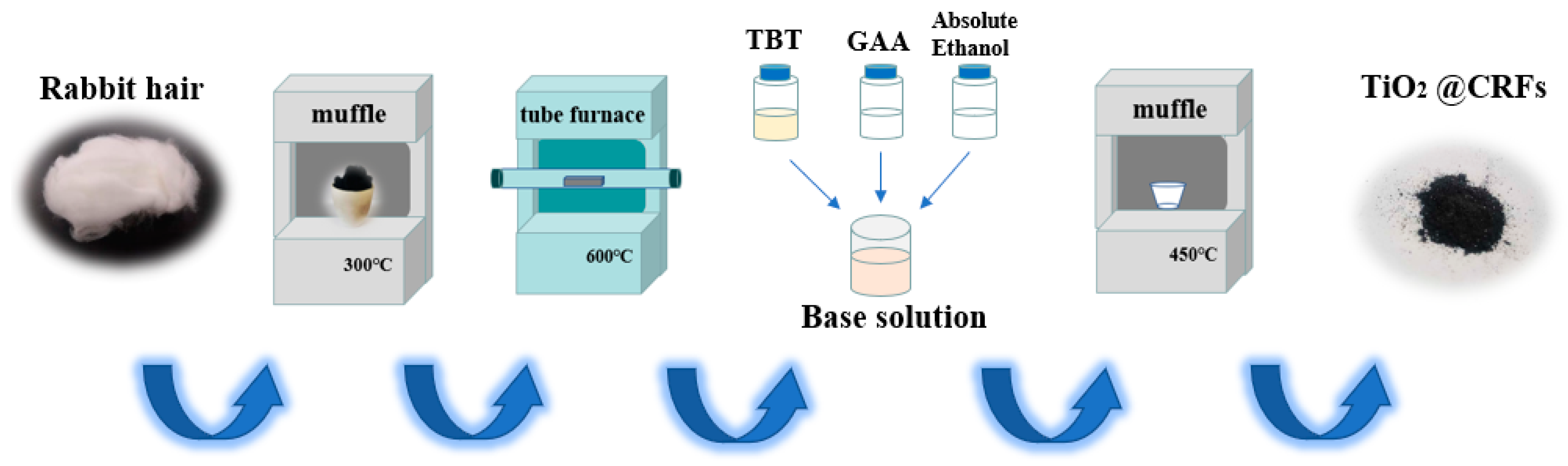
2.2. Preparation of CRFs Carbon Carrier

In order to remove impurities, the rabbit hair was washed with distilled water three times and then dried for 12 h at 80 °C. Subsequently, the rabbit fiber was pretreated in the muffle furnace at 300 °C with a rate of 2 °C min−1 in an open-air atmosphere for 90 min to maintain its hollow shape during the carbonization process. Finally, it was carbonized for 1 h at 600 °C with a rate of 2 °C min−1 under a nitrogen atmosphere in the tube furnace to obtain carbonized rabbit hair fiber (CRF).

2.3. Fabrication of TiO2/Carbonized Rabbit Hair Fibers Composites (TiO2/CRFs)

The impregnated solution was prepared by blending tetrabutyl titanate, glacial acetic acid, and anhydrous ethanol with a mass ratio of 1:2:4. Subsequently, the CRFs were added into the above-impregnated solution with different mass ratios of tetrabutyl titanate (in impregnated solution) and CRF (3:1, 5:1, and 7:1). After immersion for 4 h, the solution with CRFs were transferred to a vacuum oven (70 °C) for drying. Finally, the dried samples were calcinated to 450 °C for 1 h in a muffle furnace with a heating rate of 5 °C min−1. The obtained TiO2/CRFs composites were labeled as TiO2/CRFs = 3:1, TiO2/CRFs = 5:1, and TiO2/CRFs = 7:1 according to different mass ratios during the immersion process, respectively. The schematic of the formation of TiO2/CRFs composite materials was distinctly presented in Figure 1.

2.4. Characterization

The surface morphologies of CRFs and TiO2/CRFs were examined with a field emission scanning electron microscope (FE-SEM, Gemini SEM500, Oberkochen, Germany) after sputtering a thin gold layer. Meanwhile, the elemental mapping was obtained by energy disperse spectroscopy (EDS) connected to the FE-SEM. The crystalline phases of the samples were confirmed with X-ray diffraction (XRD) method using a Bruker AXS D8 Discover machine, and the diffraction angle 2θ was recorded from 10° to 80° with Ni-filtered CuKα radiation (λ = 0.154 nm). Moreover, the thermal properties were investigated by thermogravimetric analysis (TGA, NSK, TG/DTG 6300) under the air atmosphere at a heating rate of 10 °C min−1. The specific surface areas and pore size distribution of the synthesized samples were measured via physical adsorption at 77 K (BET, Quantachrome Instruments Autosorb-iQ, Boynton Beach, Florida, USA) following the nitrogen adsorption-desorption isotherms. In addition, the surface elemental composition of TiO2/CRFs was analyzed using an X-ray photoelectron spectroscopy (XPS) (K-al phaX, Thermo Fisher Co., Waltham, MA, USA). Fourier transform infrared spectra were carried out by diffused reflectance using a Fourier transform infrared spectrometer (FTIR, Nicolet iS50, Thermo Fisher Co., Ltd., Waltham, MA, USA). The UV-visible diffuse reflectance spectra were measured by a UV-visible diffuse reflectance spectrophotometer (Mapada UV-1800, Shanghai, China), and the spectra were recorded at room temperature in the air from 200 to 800 nm.

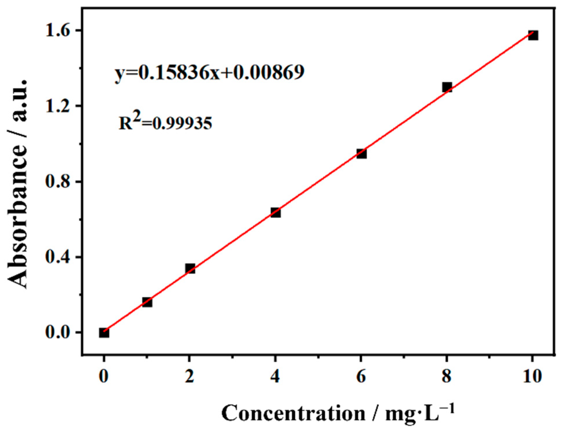
2.5. Evaluation of Photocatalytic Activity

Methylene blue (MB) is a common dye, which is extensively used in various industrial applications. In this study, the performance of the catalyst was tested by photocatalytic degradation of MB dyes. An appropriate amount (10 mg L−1) of MB was taken to simulate the wastewater and diluted with different multiples to obtain the MB solution with concentrations of 1, 2, 4, 6, 8, and 10 mg L−1, respectively. The standard working curve of MB solution was obtained by measuring the absorbance of MB solution at different concentrations, which was shown in Figure 2. After numerical fitting, the concentration of MB solution C (mg L−1) is linearly related to its absorbance A within a certain range, which can be approximately expressed as: A = 0.15836 C (R2 = 0.99935). Subsequently, an appropriate amount of photocatalyst was placed in 60 mL MB solution. First, they were stirred in a dark environment (300 r min−1) for 30 min to achieve adsorption equilibrium. Then, the beaker is exposed to ultraviolet light generated by an 18w UV lamp (the main wave peak is at 365 nm and the UV lamp is at 30 cm of the beaker) and solar light. Samples are taken at regular intervals to measure the absorbance at different times.

3. Results

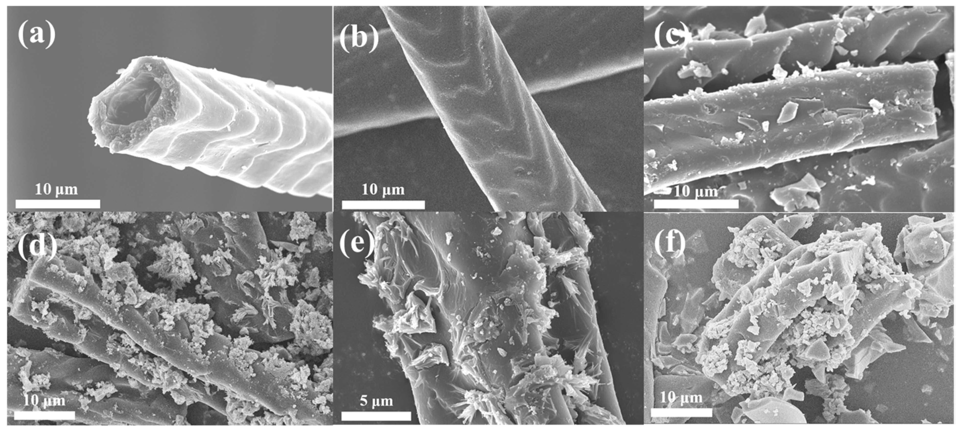
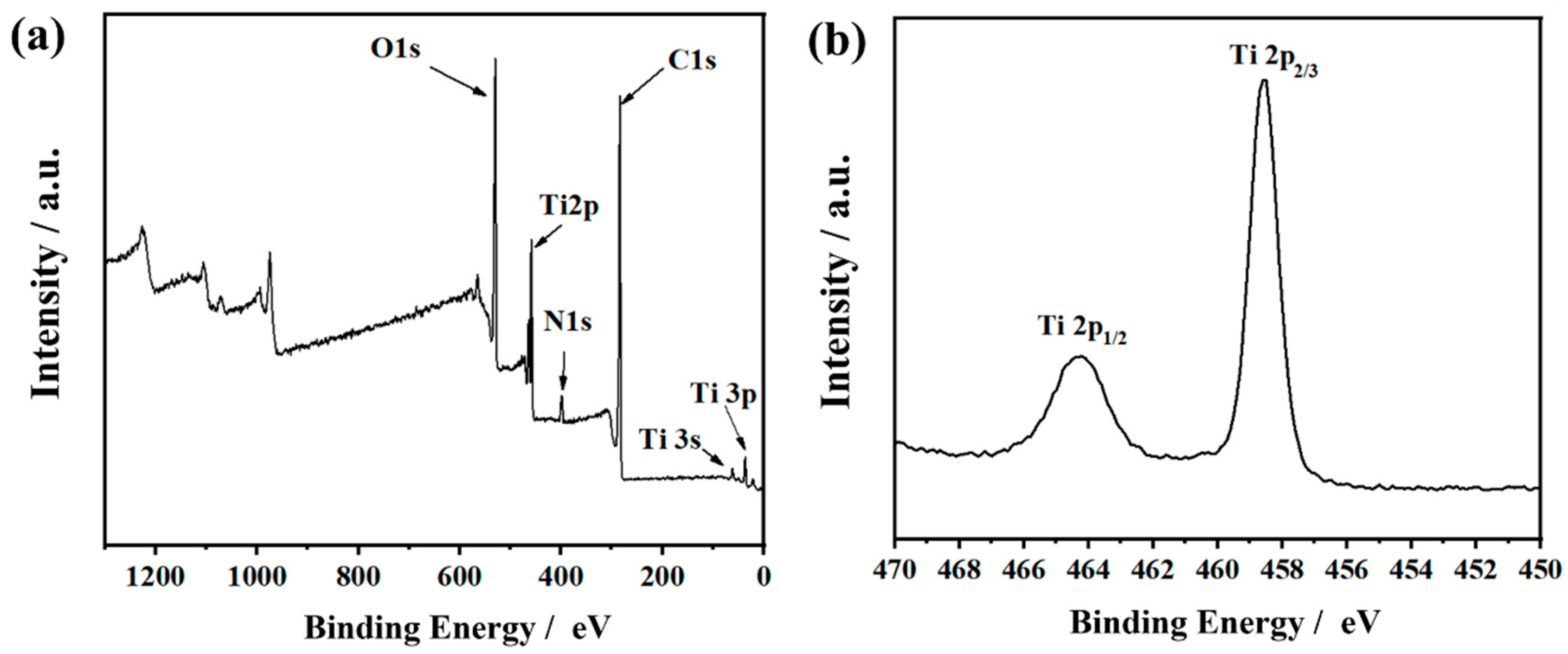
3.1. Morphologies and Chemical Properties

The morphologies for raw rabbit hair and carbonized rabbit hair fibers were presented in Figure 3a,b, respectively. It can be observed from Figure 3b that the surface of carbonized rabbit hair fiber has a rough cuticle layer, which is attribute to the special scale structure of the rabbit hair. In addition, the rough scale layer exposes more binding sites, which is more conducive to the loading of TiO2 particles. The SEM images of TiO2/CRFs with different doping contents of TiO2 nanoparticles are shown in Figure 3c–f. It can be seen that the number of TiO2 nanoparticles increases as the amount of immersion solution increases. When the mass ratio of TiO2 and CRFs is 3:1 (Figure 3c), there is only a small amount of TiO2 nanoparticles attached to the CRFs. When the mass ratio of TiO2/CRFs is 5:1 (Figure 3d,e), more TiO2 nanoparticles are distributed in the scale layer of CRF, forming a uniform layered structure [30]. However, as the ratio continues to grow, when the mass ratio of TiO2/CRFs reaches 7:1, TiO2 nanoparticles seem to be agglomerated (Figure 3f). By contrast, when the mass ratio of TiO2/CRFs is 5:1, the distribution of TiO2 nanoparticles is more uniform, which would provide more active sites in the catalysis process.
Figure 4 presents the X-ray energy dispersive spectrum of CRFs and TiO2/CRFs (TiO2/CRFs = 5:1). It indicates that there are five elements, including C, N, O, S and Ti, that exist in the composite material. Among them, C, N and S element derives from carbonized rabbit hair fiber as well as Ti and O coming from loaded nanoparticles.
Figure 5a presents XRD patterns of CRFs, TiO2, and TiO2/CRFs. The XRD pattern corresponding to CRFs shows a broad peak (2θ = 26°). This angle corresponds to the graphite phase of carbon, which proves the formation of the graphite phase during carbonization [31]. In addition, it can be observed that the prepared TiO2/CRFs = 5:1 has the same XRD pattern peaks with pure anatase TiO2 (JCPDS No.21-1272) [32]. It is known that TiO2 has three crystal forms: anatase, brookite, and rutile. Among them, anatase TiO2 has a low dielectric constant, low mass density, and high electron mobility, and the oxygen vacancies are larger than brookite crystals and rutile crystals, so anatase crystals have the highest catalytic activity [33]. In short, this article successfully synthesized a TiO2/CRFs composite catalyst with anatase crystal form, indicating its higher photocatalytic activity.
To confirm the contents of TiO2 in TiO2/CRFs = 5:1 composite material, the TG/DTG curves of TiO2/CRFs were presented in Figure 5b. The degradation occurred within a wider temperature range and showed two well separated processes in the DTG curves. The first thermal mass loss in the heating process occurred between 20 and 100 °C, corresponding to the evaporation of water molecules. The second mass loss occurred when the temperature was between 500 and 600 °C, which corresponds to the thermal decomposition of CRFs. At the same time, due to the high melting point, the remaining material is TiO2. The results showed that the high loading mass ratio of TiO2 into the TiO2/CRFs was up to 57.31%, which was benefited from the cuticle layer and pore structure of CRFs (as shown in Figure 3d).
The low-temperature nitrogen adsorption-desorption isotherm curves of TiO2/CRFs samples with different mass ratios were illustrated in Figure 5c. According to the standard IUPAC classification, the low-temperature nitrogen adsorption isotherm patterns of all samples belong to a combination of type I and IV isotherms, indicating that the pore structure of TiO2/CRFs materials has a variable distribution and a multi-scale pore structure [34]. The adsorption and desorption curves in Figure 5c are inconsistent, and hysteresis loops can be observed. According to the standard IUPAC, TiO2/CRF presents H4-type hysteresis loops, which are mostly found in solids with narrow fissure pores, distinguished from particle stacking. It is a kind of hole similar to that produced by the layered structure, in accordance with the previous SEM image showing that TiO2 particles are mostly stacked at the scale layer of CRFs, showing a layered distribution. Combined with the pore size distribution plots of the TiO2/CRFs samples in Figure 5d, TiO2/CRFs have more micropores (<2 nm) compared with CRFs, mainly because a small amount of TiO2 nanoparticle loading fills and plugs part of the mesopores (2–50 nm) in CRFs, forming a hierarchical micropore/mesopore structure. With the increase of TiO2 nanoparticles up to the amount of CRFs/TiO2 = 1:7, the number of mesopores increases, which may be due to the excessive accumulation of TiO2 nanoparticles in the fiber scale layer and the formation of larger mesopores between the particles. The hierarchical microporous/mesoporous structure endows TiO2/CRFs materials with higher light-trapping ability, shorter transport distance of photo-excited electron/hole, and higher specific surface area. Abundant pore channels afford a more effective transport path and facilitate the spread of molecules in the reaction process. Additionally, a porous structure can also promote the migration of electrons, which has been shown to suppress the carrier recombination [35].
The XPS spectra of TiO2/CRFs were presented in Figure 6, which presented that it predominantly contained N, Ti, C, and O elements [28]. The Ti 2p characteristic peaks observed at 459.0 and 464.8 eV were attributed to the existence of Ti4+ in TiO2/CRFs [32]. The high-resolution XPS spectrum of C 1s was shown in Figure 7a. Many peaks within the range of 282 eV to around 292 eV may be ascribed to the C–C (284.5 eV), C=C (285.2 eV), C–O (286 eV), and C=O (289.1 eV) bonds. Compared with CRFs, the peak area of C=C decreases, and the peak area of C-C increases in TiO2/CRFs, which indicates that C=C sp2 hybridization (graphite state) is converted to C-C sp3 hybridization. It is shown that the heteroatoms (including O, Ti, etc.) are bonded in the form of chemical bonds on carbon fibers instead of simple intermolecular binding [36]. The spectrum of O 1s is given in Figure 7b. The binding energy (BE) values of the individual components are 530.5 (Ti4+-O), 531.6 (Ti3+-O), and 532.76 eV (OH). Compared with pure TiO2, the appearance of O-Ti3+ in TiO2/CRFs proves that the defect concentration increased and the TiO2/CRFs display negative O-Ti4+ BE shift in the O 1s level, which further confirms the formation of O–Ti–N bonds [25]. The N1s XPS spectra for TiO2/CRFs are shown in Figure 7c. The N element comes from the natural rabbit hair, and it is successfully doped into TiO2 during prepared processes. The broad peak can be fitted by four peaks at 398.2, 399.5, 400.7, and 397.0 eV, suggesting four independent environments for N within TiO2/CRFs. Regarding CRFs materials, three types of N doping in carbon materials can be determined, namely Pyridinic N, Pyrrolic N, and graphitic N [37]. On the one hand, TiO2/CRFs have an N-Ti peak than CRFs, which proves the doping of N in TiO2 crystals and the chemical bonding of TiO2 crystal with N element in CRFs. On the other hand, the content of pyrrole N in TiO2/CRFs increased significantly, which is presumed to be caused by the etching effect of glacial acetic acid on CRFs during the co-heating process. This also means that the N element changes from the state of connecting carbon atoms (Pyridinic and graphitic Nitrogen) to the transition trend of connected heteroatom states (Pyrrolic Nitrogen). This transformation may be beneficial to generate more active sites that can be combined with Ti.
Figure 7d shows the FTIR spectra of CRFs and TiO2/CRFs. The two samples have similar spectra with the strong and broad absorption bands around 3400 cm−1 attributed to surface hydroxyl groups and absorbed water molecules [38]. The positions of 2965 cm−1 and 2863 cm−1 are -CH2- stretching vibration bands [22]. The strong band located at 500~700 cm−1 in TiO2/CRFs attribute to Ti–O stretching and Ti–O–Ti bridging stretching modes [28]. The peak at around ~1630 cm−1 corresponds to bending vibrations of O–H and N–H [28], and the band at around 1474 cm−1 is attributed to the vibrations of the Ti–N bond [25]. The appearance of the N–Ti bond in the samples suggests that the N species have been incorporated into the TiO2 lattice. This finding is in accordance with the XPS result previously discussed.

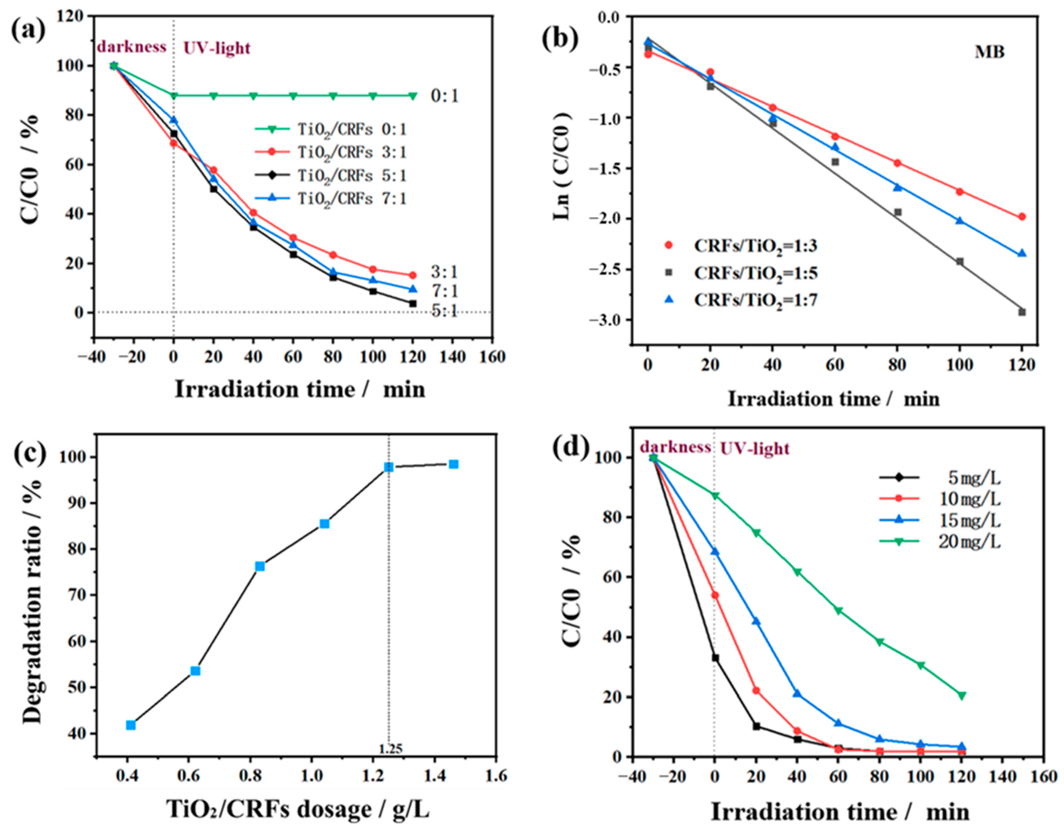
3.2. Photocatalytic Activity Performance

Figure 8a shows the photocatalytic degradation activity of MB with different loads of TiO2/CRFs. The as-prepared TiO2/CRFs are systematically evaluated under the condition that the mass concentration of MB was 10 mg L−1 (60 mL) and the sample amount of TiO2/CRFs was 50 mg. It is known from the literature that in the dark adsorption process, bare TiO2 basically has no adsorption effect on MB [39,40]. In the case of dark reaction for the first 30 min, TiO2/CRFs = 3:1 has the best adsorption performance, which is because the specific surface area of TiO2/CRFs = 3:1 is much larger than those of TiO2/CRFs = 5:1 and TiO2/CRFs = 7:1 (as listed in Table 1). In the following reaction under UV light, it is obvious that the photocatalytic degradation efficiency of MB solution first improves as the ratio of TiO2 and CRFs increasing. The reason could be explained that the increase of TiO2 load brings more active reaction sites. As the ratio of the two further increases, the degradation efficiency of the sample to MB solution decreases. This is because the TiO2 load continues to increase but the dispersibility is relatively poor, which reduces the effective adsorption of MB molecules and results in the reduction of the degradation efficiency. When the TiO2/CRFs = 5:1, the degradation efficiency of the sample to MB solution reached the maximum.
To determine the photocatalytic reaction rate, an attempt is made to fit the data using some common kinetic equations, which are shown in Figure 8b. The first-order kinetics is then confirmed by making a linear plot l n C / C 0 against time. The kinetic equation could be expressed as follows [41,42]:
l n C C 0 = k t
where C 0 is the concentration of the reactant before illumination (mg L−1); C is the concentration of the reactant after a certain illumination period t (mg L−1); k is the first-order rate constant (min−1) and t is the illumination time (min).
The kinetics of MB photoreduction with different samples are illustrated in Figure 8b, respectively. It is clearly seen that the photooxidation of MB follows a first-order kinetics equation. Figure 8c shows the influence of TiO2/CRFs = 5:1 dosage on the degradation performance of MB solution under the conditions of UV-light irradiation for 60 min and MB solution concentration of 10 mg L−1. It can be seen that the degradation rate of MB solution increases with the increase of TiO2/CRFs dosage. Specifically, when the dosage of TiO2/CRFs was 0.41 g L−1, 1.25 g L−1 and 1.46 g L−1, the degradation rates of MB solution were 41.9%, 97.9% and 98.3% respectively. However, when the amount of TiO2/CRFs is greater than 1.25 g L−1, the degradation rate of MB solution does not increase significantly. This is because increasing the amount of TiO2/CRFs at the beginning can increase the number of surface activity sites of TiO2 photocatalyst, thus increasing the degradation rate of MB solution [43]. However, due to the limited area of TiO2/CRFs photocatalyst exposed to UV-light, and the excessive TiO2/CRFs photocatalyst will block UV light, increasing the amount of TiO2/CRFs will not significantly improve the degradation rate. Therefore, in the photocatalytic experiment (60 mL 10 mg L−1 MB), the optimal amount of TiO2/CRFs photocatalyst is 1.25 g L−1, and the degradation rate can reach 97.9%. Compared with bare TiO2, the degradation rate of MB solution is only 85.35% when the UV lamp is irradiated within 60 min. [40]. Figure 8d shows the photocatalytic degradation activity with different MB concentrations under the condition that the sample of TiO2/CRFs = 5:1 was 1.25 g L−1 and the volume of MB was 60 mL. The degradation rates of the samples after 60 min of irradiation were 98.0% (5 mg L−1 MB), 97.9% (10 mg L−1 MB), 88.8% (15 mg L−1 MB) and 50.9% (20 mg L−1 MB), respectively. By comparison, the photocatalyst efficiency is similar when MB concentrations are 5 mg L−1 and 10 mg L−1, so the MB solution with a concentration of 10 mg L−1 is an appropriate choice.
The above three experiments (Figure 6c,d and Figure 8a) were designed to explore the proportion, dosage, and appropriate MB concentration of TiO2/CRFs composite materials under more stable conditions. However, in the face of industrial application, it is very important that dyes can be directly degraded by visible light irradiation. Therefore, the solar photocatalytic degradation activity of TiO2/CRFs has been shown in Figure 9a. Moreover, to further compare the advantages of rabbit fur as a carrier, Figure 9a also shows the comparison of photocatalytic degradation activities of TiO2/CRFs and TiO2/Cotton fibers under the condition of sunlight. The degradation rates of the two samples after 80 min of sunlight irradiation are 98.1% and 43.3%, respectively. According to a large amount of literature that has focused on the photocatalytic activity mechanism of N-doped TiO2, it is generally believed that N doping in TiO2 lattice changes the electronic band structure of TiO2, resulting in the formation of a new substituted N 2p band above the O 2p valence band, which reduces the band gap of TiO2 and transfers the optical absorption to the visible region [26,28,44]. In Figure 9a, the photocatalytic degradation activity of TiO2/CRFs in sunlight is significantly stronger than that of TiO2/Cotton fibers. It can be determined that this phenomenon is due to the N-doping of TiO2/CRFs, which decreased band-gap energy of the catalyst and thus enhances the solar energy absorption. Figure 9b shows the sunlight absorption curve of the TiO2/CRFs composite. It can be seen that the maximum absorbance value of MB is significantly reduced, and nearly all MB is degraded after 80 min of sunlight irradiation, indicating TiO2/CRFs have a significant photocatalytic degradation effect on MB.
Figure 10 shows the possible degradation mechanism of MB by TiO2/CRFs photocatalyst. After light irradiation, TiO2 nanoparticles generate electron-hole pairs after absorbing light with energy equal to or greater than the bandgap energy of TiO2 nanoparticles. These light-generated charge carriers are responsible for the photocatalytic degradation of MB by TiO2 nanoparticles. However, the rapid recombination of photogenerated electron-hole pairs leads to the low photocatalytic activity of TiO2 nanoparticles. The combination of TiO2 nanoparticles and CRFs nanomaterials improves photocatalytic efficiency mainly through two mechanisms, including greater adsorption on MB and feasible charge separation and transport. According to a series of carbonaceous–TiO2 composites with unique morphologies shown in Ref. [45], the carbonaceous nanomaterials can significantly increase the dye concentration on the photocatalyst surface with good adsorption properties. The results indicated that the bulk adsorption performance of dye molecules on the photocatalyst surface is a key factor to improve photocatalytic activity. In addition, the carbonaceous nanomaterials can play the central role of electron reservoir to obtain electrons from the electron-hole pairs of TiO2, thus improving the charge separation efficiency of TiO2. As seen in Figure 10, when TiO2 nanoparticles are irradiated by light, they may generate electrons in the conduction band (CB) and holes in the valence band (VB), and may also form reactive substances such as OH and O2− [46,47]. Therefore, the generated cavities and oxidizing species will break down the MB into CO2 and water by hydroxylation. Furthermore, it is known that carbonaceous nanomaterials can act as electron traps, allowing the rapid transfer of a fraction of photogenerated electrons from TiO2 nanoparticles CB to carbonaceous nanomaterials and the effective separation of photogenerated charge carriers [45]. Thus, electrons are transferred to the surface where they react with adsorbed oxygen (O2) to produce highly reactive superoxide radical anions (O2−), while cavities can oxidize H2O to OH radicals [48,49,50]. The stability of the photocatalyst under solar light irradiation is an essential indicator of the performance of photocatalytic degradation. TiO2/CRFs were centrifuged and reclaimed for MB degradation at a similar dye concentration. The regeneration analysis of the degradation of MB dye by TiO2/CRFs under natural solar light irradiation is exhibited in Figure 9c. From the results of regeneration cycles, the degradation efficiency of TiO2/CRFs of MB was reduced by 3.9% compared with the first cycle, indicating that the catalyst has a good persistent catalytic ability. Figure 11 shows before and after photocatalytic degradation of methylene blue solution. Table 2 shows the comparison of the results of the TiO2/CRFs prepared in this study with other titanium dioxide composite photocatalysts in the literature for the degradation of MB, and it was found that the TiO2/CRFs prepared in this study had a significant advantage in degrading MB, maintaining a high level of effectiveness.

4. Conclusions

In this study, a novel TiO2/CRFs nanocomposite photocatalyst was designed by combining carbonization, impregnation, and calcination processes with improved photocatalytic performance and excellent stability. TiO2/CRFs are naturally doped with carbon and nitrogen elements from waste rabbit hair, which effectively reduce the compounding of photogenerated electron-hole pairs and the band gap of TiO2, and the absorption of visible light is enhanced, thereby greatly improving the photocatalytic activity of TiO2. Its large specific surface area and special hierarchical micropore/mesopore structure provide abundant active sites for the adsorption of reactants, and the multiple reflections in the pore structure enhance the light-trapping ability of the material. Thereby, efficient charge separation and strong light-harvesting capability are achieved, realizing the ultimate goal of the removal of methylene blue under visible light. The experiments showed that the photocatalytic degradation of MB solution by TiO2/CRFs could reach 98.1% after 80 min solar irradiation at the initial concentration of MB 10 mg/L, the ratio of TiO2/CRFs 5:1, and material dosage 1.25 g/L. In addition, the TiO2/CRFs photocatalyst can be easily recovered with only 3.9% loss of photocatalytic activity after five cycles. Further systematic studies on TiO2 doping with C and N will be conducted in the future. In consideration of the low cost and waste reuse of rabbit hair, as well as the no-toxic and high photocatalytic performance of TiO2, this work undoubtedly provides an economic and environmental strategy for the preparation of biochar/TiO2 composite photocatalysts. It is competitive among related materials and provides experimental basis for the subsequent photocatalytic research of carbon fiber and TiO2 composite nanomaterials.

Author Contributions

Data curation, J.C.; Formal analysis, Y.C.; Funding acquisition, W.K.; Investigation, S.W.; Project administration, J.J.; Resources, W.K.; Supervision, J.J.; Validation, C.W.; Writing—original draft, Y.C.; Writing—review & editing, C.W. All authors have read and agreed to the published version of the manuscript.

Funding

This research was funded by the National Natural Science Foundation of China (51973157), Project funded by China Postdoctoral Science Foundation (2021T140419), the Science and Technology Plans of Tianjin (19PTSYJC00010), TGU Grant for Fiber Studies (TGF-21-B9), the Science & Technology Development Fund of Tianjin Education Commission for Higher Education (2018KJ196) and State Key Laboratory of Membrane and Membrane Separation, Tiangong University.

Institutional Review Board Statement

Not applicable.

Informed Consent Statement

Not applicable.

Data Availability Statement

Not applicable.

Conflicts of Interest

The authors declare that there is no conflict of interest regarding the publication of this article.

References

  1. Jain, P.; Kumar, A.; Verma, N.; Gupta, R.K. In-situ synthesis of TiO2 nanoparticles in ACF: Photocatalytic degradation under continuous flow. Sol. Energy 2019, 189, 35–44. [Google Scholar] [CrossRef]
  2. Bahrudin, N.N.; Nawi, M.A.; Nawawi, W.I. Photocatalytic enhancement of immobilized TiO2-polyaniline bilayer (TiO2-PBL) system for decolorization of methyl orange dye. Mater. Res. Bull. 2018, 106, 388–395. [Google Scholar] [CrossRef]
  3. Hu, H.X.; Pang, B.Y.; Zhu, Y.F.; Fu, Y.Q. Preparation of titanium dioxide immobilized on carbon fibers annealed in steam ambient and their photocatalytic properties. Text. Res. J. 2017, 87, 2233–2241. [Google Scholar] [CrossRef]
  4. Seabold, J.A.; Choi, K.-S. Effect of a Cobalt-Based Oxygen Evolution Catalyst on the Stability and the Selectivity of Photo-Oxidation Reactions of a WO3Photoanode. Chem. Mater. 2011, 23, 1105–1112. [Google Scholar] [CrossRef]
  5. Choudhary, S.; Hasina, D.; Saini, M.; Ranjan, M.; Mohapatra, S. Facile synthesis, morphological, structural, photocatalytic and optical properties of ZnFe2O4-ZnO hybrid nanostructures. J. Alloy. Compd. 2022, 895, 162723. [Google Scholar] [CrossRef]
  6. Murata, N.; Suzuki, T.; Kobayashi, M.; Togoh, F.; Asakura, K. Characterization of Pt-doped SnO2 catalyst for a high-performance micro gas sensor. Phys. Chem. Chem. Phys. 2013, 15, 17938–17946. [Google Scholar] [CrossRef] [Green Version]
  7. Wang, H.P.; Guan, Z.C.; Shi, H.Y.; Wang, X.; Jin, P.A.; Song, G.L.; Du, R.G. Ag/SnO2/TiO2 nanotube composite film used in photocathodic protection for stainless steel. J. Photochem. Photobiol. A-Chem. 2021, 417, 113353. [Google Scholar] [CrossRef]
  8. Chen, P. A promising strategy to fabricate the Cu/BiVO4 photocatalysts and their enhanced visible-light-driven photocatalytic activities. J. Mater. Sci. Mater. Electron. 2015, 27, 2394–2403. [Google Scholar] [CrossRef]
  9. Lv, Y.-R.; Liu, C.-J.; He, R.-K.; Li, X.; Xu, Y.-H. BiVO4/TiO2 heterojunction with enhanced photocatalytic activities and photoelectochemistry performances under visible light illumination. Mater. Res. Bull. 2019, 117, 35–40. [Google Scholar] [CrossRef]
  10. Zhou, L.; Wang, W.; Xu, H.; Sun, S.; Shang, M. Bi2O3 Hierarchical Nanostructures: Controllable Synthesis, Growth Mechanism, and their Application in Photocatalysis. Chem. A Eur. J. 2009, 15, 1776–1782. [Google Scholar] [CrossRef]
  11. Zou, H.; Song, M.; Yi, F.; Bian, L.; Liu, P.; Zhang, S. Simulated-sunlight-activated photocatalysis of Methyl Orange using carbon and lanthanum co-doped Bi2O3–TiO2 composite. J. Alloy. Compd. 2016, 680, 54–59. [Google Scholar] [CrossRef]
  12. Ding, P.R.; Ji, H.D.; Li, P.S.; Liu, Q.M.; Wu, Y.Y.; Guo, M.; Zhou, Z.A.; Gao, S.; Xu, W.L.; Liu, W.; et al. Visible-light degradation of antibiotics catalyzed by titania/zirconia/graphitic carbon nitride ternary nanocomposites: A combined experimental and theoretical study. Appl. Catal. B Environ. 2022, 300, 120633. [Google Scholar] [CrossRef]
  13. Wang, H.; Chen, Q.; Luan, Q.; Duan, R.; Guan, R.; Cao, X.; Hu, X. Photocatalytic Properties Dependent on the Interfacial Defects of Intergrains within TiO2 Mesocrystals. Chemistry 2018, 24, 17105–17116. [Google Scholar] [CrossRef] [PubMed]
  14. Zhu, L.; Meng, Z.; Trisha, G.; Oh, W.C. Hydrothermal Synthesis of Porous Ag2S Sensitized TiO2 Catalysts and Their Photocatalytic Activities in the Visible Light Range. Chin. J. Catal. 2012, 33, 254–260. [Google Scholar] [CrossRef]
  15. Nagaveni, K.; Sivalingam, G.; Hegde, M.S.; Madras, G. Solar photocatalytic degradation of dyes: High activity of combustion synthesized nano TiO2. Appl. Catal. B: Environ. 2004, 48, 83–93. [Google Scholar] [CrossRef]
  16. Maeda, K. Photocatalytic properties of rutile TiO2 powder for overall water splitting. Catal. Sci. Technol. 2014, 4, 1949–1953. [Google Scholar] [CrossRef]
  17. Turkten, N.; Bekbolet, M. Photocatalytic performance of titanium dioxide and zinc oxide binary system on degradation of humic matter. J. Photochem. Photobiol. A-Chem. 2021, 417, 113281. [Google Scholar] [CrossRef]
  18. Inagaki, M.; Kojin, F.; Tryba, B.; Toyoda, M. Carbon-coated anatase: The role of the carbon layer for photocatalytic performance. Carbon 2005, 43, 1652–1659. [Google Scholar] [CrossRef]
  19. Tryba, B.; Morawski, A.W.; Tsumura, T.; Toyoda, M.; Inagaki, M. Hybridization of adsorptivity with photocatalytic activity—carbon-coated anatase. J. Photochem. Photobiol. A Chem. 2004, 167, 127–135. [Google Scholar] [CrossRef]
  20. Tsumura, T.; Kojitani, N.; Izumi, I.; Iwashita, N.; Toyoda, M.; Inagaki, M. Carbon coating of anatase-type TiO2 and photoactivity. J. Mater. Chem. 2002, 12, 1391–1396. [Google Scholar] [CrossRef]
  21. Wang, B.; Karthikeyan, R.; Lu, X.Y.; Xuan, J.; Leung, M.K. High photocatalytic activity of immobilized TiO2 nanorods on carbonized cotton fibers. J. Hazard. Mater. 2013, 263 Pt 2, 659–669. [Google Scholar] [CrossRef] [PubMed]
  22. Cheng, G.; Xu, F.F.; Xiong, J.Y.; Tian, F.; Ding, J.; Stadler, F.J.; Chen, R. Enhanced adsorption and photocatalysis capability of generally synthesized TiO2-carbon materials hybrids. Adv. Powder Technol. 2016, 27, 1949–1962. [Google Scholar] [CrossRef]
  23. Nguyen, C.H.; Fu, C.-C.; Juang, R.-S. Degradation of methylene blue and methyl orange by palladium-doped TiO2 photocatalysis for water reuse: Efficiency and degradation pathways. J. Clean. Prod. 2018, 202, 413–427. [Google Scholar] [CrossRef]
  24. Orooji, Y.; Tanhaei, B.; Ayati, A.; Tabrizi, S.H.; Alizadeh, M.; Bamoharram, F.F.; Karimi, F.; Salmanpour, S.; Rouhi, J.; Afshar, S.; et al. Heterogeneous UV-Switchable Au nanoparticles decorated tungstophosphoric acid/TiO2 for efficient photocatalytic degradation process. Chemosphere 2021, 281, 130795. [Google Scholar] [CrossRef] [PubMed]
  25. Huo, Y.; Jin, Y.; Zhu, J.; Li, H. Highly active TiO2−x−yNxFy visible photocatalyst prepared under supercritical conditions in NH4F/EtOH fluid. Appl. Catal. B Environ. 2009, 89, 543–550. [Google Scholar] [CrossRef]
  26. Powell, M.J.; Palgrave, R.G.; Dunnill, C.W.; Parkin, I.P. A fast and effective method for N-doping TiO2 by post treatment with liquid ammonia: Visible light photocatalysis. Thin Solid Film. 2014, 562, 223–228. [Google Scholar] [CrossRef]
  27. Zhang, X.L.; Yuan, N.; Li, Y.; Han, L.J.; Wang, Q.B. Fabrication of new MIL-53(Fe)@TiO2 visible-light responsive adsorptive photocatalysts for efficient elimination of tetracycline. Chem. Eng. J. 2022, 428, 131077. [Google Scholar] [CrossRef]
  28. Yang, G.; Jiang, Z.; Shi, H.; Xiao, T.; Yan, Z. Preparation of highly visible-light active N-doped TiO2 photocatalyst. J. Mater. Chem. 2010, 20, 5301–5309. [Google Scholar] [CrossRef]
  29. Wang, X.Q.; Shi, Z.M.; Zhao, Q.L.; Yun, Y. Study on the Structure and Properties of Biofunctional Keratin from Rabbit Hair. Materials 2021, 14, 379. [Google Scholar] [CrossRef]
  30. Kiatkittipong, K.; Lim, J.W.; Cheng, C.K.; Kiatkittipong, W.; Assabumrungrat, S. Simultaneous Enhancement of Photocatalytic Bactericidal Activity and Strength Properties of Acrylonitrile-Butadiene-Styrene Plastic Via a Facile Preparation with Silane/TiO2. Polymers 2020, 12, 917. [Google Scholar] [CrossRef]
  31. Eom, Y.; Son, S.M.; Kim, Y.E.; Lee, J.E.; Hwang, S.H.; Chae, H.G. Structure evolution mechanism of highly ordered graphite during carbonization of cellulose nanocrystals. Carbon 2019, 150, 142–152. [Google Scholar] [CrossRef]
  32. Ju, J.; Lv, Y.; An, X.; Liu, W.; Li, Z.; Kang, W.; Cheng, B. The stereoscopic honeycomb-like porous carbon nanofibers as a carrier of TiO2 nanoparticles for high-performance Li-ion capacitor. J. Alloy. Compd. 2019, 791, 1248–1256. [Google Scholar] [CrossRef]
  33. Katal, R.; Masudy-Panah, S.; Tanhaei, M.; Farahani, M.; Hu, J.Y. A review on the synthesis of the various types of anatase TiO2 facets and their applications for photocatalysis. Chem. Eng. J. 2020, 384, 123384. [Google Scholar] [CrossRef]
  34. Zuliani, J.E.; Tong, S.; Kirk, D.W.; Jia, C.Q. Isolating the effect of pore size distribution on electrochemical double-layer capacitance using activated fluid coke. J. Power Sources 2015, 300, 190–198. [Google Scholar] [CrossRef]
  35. Zou, X.; Yang, Y.; Chen, H.; Shi, X.-L.; Song, S.; Chen, Z.-G. Hierarchical meso/macro-porous TiO2/graphitic carbon nitride nanofibers with enhanced hydrogen evolution. Mater. Des. 2021, 202, 109542. [Google Scholar] [CrossRef]
  36. Yang, D.; Velamakanni, A.; Bozoklu, G.; Park, S.; Stoller, M.; Piner, R.D.; Stankovich, S.; Jung, I.; Field, D.A.; Ventrice, C.A.; et al. Chemical analysis of graphene oxide films after heat and chemical treatments by X-ray photoelectron and Micro-Raman spectroscopy. Carbon 2009, 47, 145–152. [Google Scholar] [CrossRef]
  37. Zhang, J.; Sun, Y.; Zhu, J.; Kou, Z.; Hu, P.; Liu, L.; Li, S.; Mu, S.; Huang, Y. Defect and pyridinic nitrogen engineering of carbon-based metal-free nanomaterial toward oxygen reduction. Nano Energy 2018, 52, 307–314. [Google Scholar] [CrossRef]
  38. Wu, Y.; Zang, Y.; Xu, L.; Wang, J.; Jia, H.; Miao, F. Synthesis of functional conjugated microporous polymer/TiO2 nanocomposites and the mechanism of the photocatalytic degradation of organic pollutants. J. Mater. Sci. 2021, 56, 7936–7950. [Google Scholar] [CrossRef]
  39. Valadez-Renteria, E.; Oliva, J.; Rodriguez-Gonzalez, V. Photocatalytic materials immobilized on recycled supports and their role in the degradation of water contaminants: A timely review. Sci. Total Environ. 2022, 807, 150820. [Google Scholar] [CrossRef]
  40. Wenqi, X.; Yang, J.; Yongsheng, B.; Jun, L.; Zhizhen, W.; Changsheng, B.; Haitao, C.; Ming, C. Synergy mechanism for TiO2/activated carbon composite material: Photocatalytic degradation ofmethylene blue solution. Can. J. Chem. Eng. 2020, 100, 276–290. [Google Scholar] [CrossRef]
  41. Camera-Roda, G.; Augugliaro, V.; Cardillo, A.G.; Loddo, V.; Palmisano, L.; Parrino, F.; Santarelli, F. A reaction engineering approach to kinetic analysis of photocatalytic reactions in slurry systems. Catalysis Today 2016, 259, 87–96. [Google Scholar] [CrossRef]
  42. Beltran, F.J.; Aguinaco, A.; Garcia-Araya, J.F. Kinetic modelling of TOC removal in the photocatalytic ozonation of diclofenac aqueous solutions. Appl. Catal. B Environ. 2010, 100, 289–298. [Google Scholar] [CrossRef]
  43. Aoudjit, L.; Salazar, H.; Zioui, D.; Sebti, A.; Martins, P.M.; Lanceros-Mendez, S. Reusable Ag@TiO2-Based Photocatalytic Nanocomposite Membranes for Solar Degradation of Contaminants of Emerging Concern. Polymers 2021, 13, 3718. [Google Scholar] [CrossRef] [PubMed]
  44. Alvaro, M.; Carbonell, E.; Fornes, V.; Garcia, H. Enhanced photocatalytic activity of zeolite-encapsulated TiO2 clusters by complexation with organic additives and N-doping. Chemphyschem 2006, 7, 200–205. [Google Scholar] [CrossRef] [PubMed]
  45. Sui, X.; Li, X.; Ni, T.; Lin, F.; Li, G. Carbonaceous–TiO2 materials: Unique morphologies for photocatalytic applications. J. Mater. Sci. 2019, 55, 2725–2740. [Google Scholar] [CrossRef]
  46. Ling, L.; Wang, C.; Ni, M.L.; Shang, C. Enhanced photocatalytic activity of TiO2/single-walled carbon nanotube (SWCNT) composites under UV-A irradiation. Sep. Purif. Technol. 2016, 169, 273–278. [Google Scholar] [CrossRef]
  47. Yun, J.; Kim, H.I.; Lee, Y.S. A hybrid gas-sensing material based on porous carbon fibers and a TiO2 photocatalyst. J. Mater. Sci. 2013, 48, 8320–8328. [Google Scholar] [CrossRef]
  48. Vital-Grappin, A.D.; Ariza-Tarazona, M.C.; Luna-Hernandez, V.M.; Villarreal-Chiu, J.F.; Hernandez-Lopez, J.M.; Siligardi, C.; Cedillo-Gonzalez, E.I. The Role of the Reactive Species Involved in the Photocatalytic Degradation of HDPE Microplastics Using C,N-TiO2 Powders. Polymers 2021, 13, 999. [Google Scholar] [CrossRef]
  49. Xu, Z.W.; Li, X.H.; Wang, W.; Shi, J.; Teng, K.Y.; Qian, X.M.; Shan, M.J.; Li, C.Y.; Yang, C.Y.; Liu, L.S. Microstructure and photocatalytic activity of electrospun carbon nanofibers decorated by TiO2 nanoparticles from hydrothermal reaction/blended spinning. Ceram. Int. 2016, 42, 15012–15022. [Google Scholar] [CrossRef]
  50. Lee, K.; Yoon, H.; Ahn, C.; Park, J.; Jeon, S. Strategies to improve the photocatalytic activity of TiO2: 3D nanostructuring and heterostructuring with graphitic carbon nanomaterials. Nanoscale 2019, 11, 7025–7040. [Google Scholar] [CrossRef]
  51. Wang, B.; Liu, B.; Ji, X.X.; Ma, M.G. Synthesis, Characterization, and Photocatalytic Properties of Bamboo Charcoal/TiO2 Composites Using Four Sizes Powder. Materials 2018, 11, 670. [Google Scholar] [CrossRef] [PubMed] [Green Version]
  52. Huy, T.H.; Phat, B.D.; Kang, F.; Wang, Y.F.; Liu, S.H.; Thi, C.M.; You, S.J.; Chang, G.M.; Viet, P.V. SnO2/TiO2 nanotube heterojunction: The first investigation of NO degradation by visible light-driven photocatalysis. Chemosphere 2019, 215, 323–332. [Google Scholar] [CrossRef] [PubMed]
  53. Lisowski, P.; Colmenares, J.C.; Masek, O.; Lomot, D.; Chernyayeva, O.; Lisovytskiy, D. Novel biomass-derived hybrid TiO2/carbon material using tar-derived secondary char to improve TiO2 bonding to carbon matrix. J. Anal. Appl. Pyrolysis 2018, 131, 35–41. [Google Scholar] [CrossRef]
  54. Ramasamy, K.; Dhavamani, S.; Natesan, G.; Sengodan, K.; Sengottayan, S.N.; Tiwari, M.; Vikram, S.S.; Perumal, V. A potential role of green engineered TiO2 nanocatalyst towards enhanced photocatalytic and biomedical applications. Environ. Sci. Pollut. Res. 2021, 28, 41207–41223. [Google Scholar] [CrossRef]
  55. Lin, Z.H.; Huang, J.G. A hierarchical H3PW12O40/TiO2 nanocomposite with cellulose as scaffold for photocatalytic degradation of organic pollutants. Sep. Purif. Technol. 2021, 264, 118427. [Google Scholar] [CrossRef]
  56. Ma, L.; Chen, Y.; Ding, Y.; Zheng, J. High-performance antibacterial film via synergistic effect between uniformly dispersed TiO2 nanoparticles and multifunctional quaternary ammonium cationic ligand. Prog. Org. Coat. 2021, 157, 106322. [Google Scholar] [CrossRef]
  57. Cheng, H.; Zhang, W.; Liu, X.; Tang, T.; Xiong, J. Fabrication of Titanium Dioxide/Carbon Fiber (TiO2CF) Composites for Removal of Methylene Blue (MB) from Aqueous Solution with Enhanced Photocatalytic Activity. J. Chem. 2021, 2021, 9986158. [Google Scholar] [CrossRef]
Figure 1. Schematic of the formation of TiO2/CRFs composite materials.
Polymers 14 01593 g001
Figure 2. The standard working curve of MB solution.
Polymers 14 01593 g002
Figure 3. SEM images of (a) rabbit hair fiber, (b) carbonized rabbit hair fiber, (c) TiO2/CRFs = 3:1, (d) TiO2/CRFs = 5:1, (e) TiO2/CRFs = 5:1 (partial enlarged detail) and (f) TiO2/CRFs = 7:1.
Polymers 14 01593 g003
Figure 4. X-ray energy dispersive spectrum of (a) CRFs and (b) TiO2/CRFs (TiO2/CRFs = 5:1).
Polymers 14 01593 g004
Figure 5. (a) XRD patterns of CRFs, TiO2 and TiO2/CTFs; (b) TG/DTG curves of TiO2/CRFs; (c) Nitrogen adsorption–desorption isotherms and (d) Pore size distribution for TiO2/CRFs.
Polymers 14 01593 g005
Figure 6. XPS spectra of (a) TiO2/CRFs and (b) Ti 2p.
Polymers 14 01593 g006
Figure 7. (ac) XPS spectra of CRFs and TiO2/CRFs: (a) C 1s, (b) O 1s, (c) N 1s. (d) FTIR spectra of CRFs and TiO2/CRFs.
Polymers 14 01593 g007
Figure 8. (a) Photocatalytic degradation activity of MB with different loads of TiO2/CRFs; (b) Linear transform ln(C/C0) = kt of the kinetic curves of dye degradation onto TiO2/CRFs under UV illuminations. (c) Effect of TiO2/CRFs Dosage on Degradation ratio of MB Solution; (d) Photocatalytic degradation activity of TiO2/CRFs with different MB concentrations.
Polymers 14 01593 g008
Figure 9. (a) Photocatalytic degradation activity of TiO2/CRFs and TiO2/Cotton fibers under the condition of sunlight; (b) Sunlight absorption curve of photodegradation of MB upon TiO2/CRFs; (c) Cycle experiments of TiO2/CRFs used for photocatalytic degradation of MB.
Polymers 14 01593 g009
Figure 10. Schematic diagram of the photocatalytic mechanism for TiO2/CRFs photocatalyst under sunlight irradiation.
Polymers 14 01593 g010
Figure 11. Image of (a) before and (b) after the photocatalytic degradation of methylene blue solution.
Polymers 14 01593 g011
Table 1. The structural parameters of TiO2/CRFs and CRFs.
SampleSpecific Surface Area
(m2 g−1)
Pore Volume
(cc g−1)
CRFs237.8280.1027
TiO2:CRFs = 3:1488.9420.2099
TiO2:CRFs = 5:1345.7570.1627
TiO2:CRFs = 7:1324.5880.1580
Table 2. Research progress in degradation of MB dye by TiO2 composite catalyst.
MaterialSynthesis MethodMB
(mg L−1)
Catalyst Loading (g L−1)Light SourceHighest DegradationCyclic DegradationRef.
TiO2200.4UV light60 min, 85.45%4 cycles, 62.49%[40]
Bamboo biochar/TiO2Calcination method12.80.2UV light60 min, 95%[51]
Visible light60 min, 97%4 cycles, 75%
SnO2/TiO2Hydrothermal techniques200.5Visible light50 min, 90%4 cycles, 87%[52]
Lignin biochar/TiO2Microwave-hydrothermal and calcination method12.80.2UV light25 min, 93%[53]
CMP/TiO2Sonogashira–Hagihara coupling reaction8.60.28Visible light60 min, 96.8%5 cycles, 93.1%[38]
Biomolecules wrapped TiO2Microwave irradiation method100.2Visible light6 h, 90.6%[54]
Hierarchical H3PW12O40/TiO2Impregnation and layer-by-layer methods100.25UV light5 min, 95%5 cycles, 65%
6 cycles after calcination, 96%
[55]
P(MMA-co-BA-coMTC)/TiO2Suspension polymerization620UV light270 min, 99.66%20 cycles, 98.7%[56]
TiO2/ACSol–gel method200.4UV light60 min, 99.43%4 cycles, 88.06%[40]
B-TiO2/CFHydrothermal method100.75UV light10 min, 76%5 cycles, slight decrease[57]
Visible light10 min, 69%
TiO2/CRFsCarbonization, impregnation and calcination method101.25UV light60 min, 97.9%This study
Visible light80 min, 98.1%5 cycles, 90.2%
Publisher’s Note: MDPI stays neutral with regard to jurisdictional claims in published maps and institutional affiliations.

