
Evaluation of Surfactants on Graphene Dispersion and Thermal Performance for Heat Dissipation Coating


Abstract
:
1. Introduction
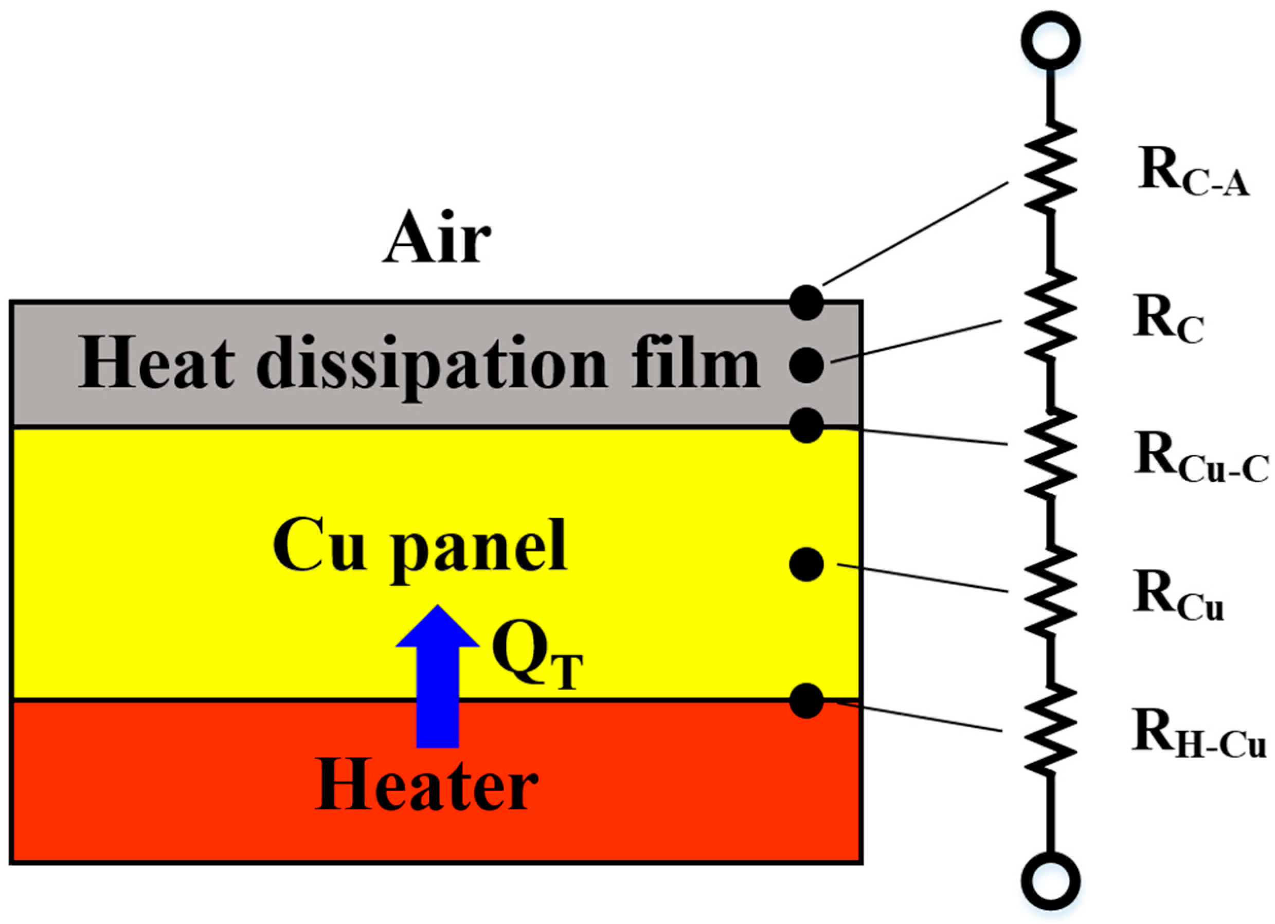
2. Related Theories
3. Experimental Methods and Procedures
3.1. Formulation of the Carbon Nanomaterial Dispersant
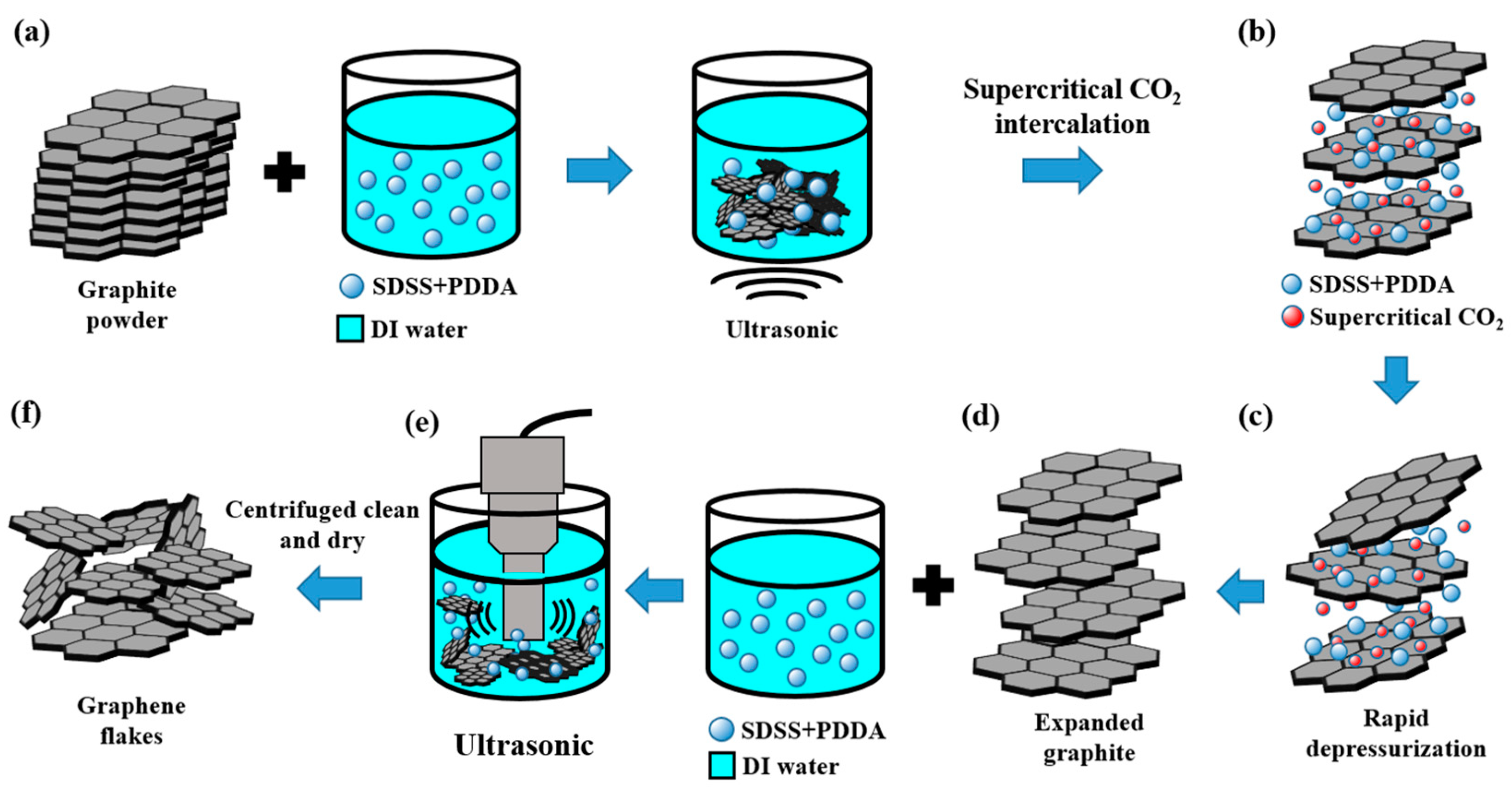
3.2. Preparation of Graphene flakXes by Supercritical CO2 Assisted Exfoliation
3.3. Formulation of the Heat Dissipation Coating
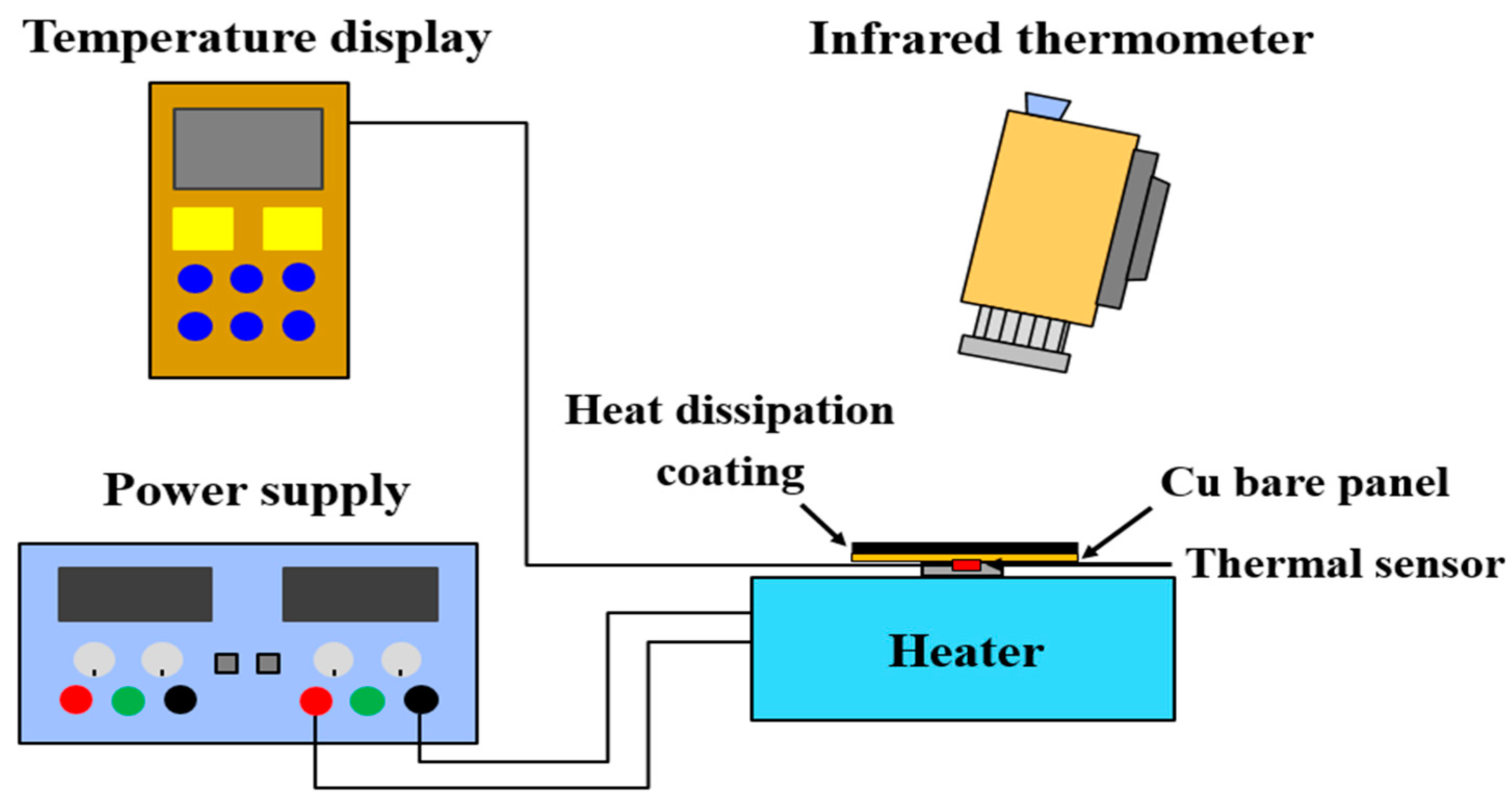
3.4. Evaluation of the Emissivity and Heat-Dissipating Performance
4. Results and Discussion
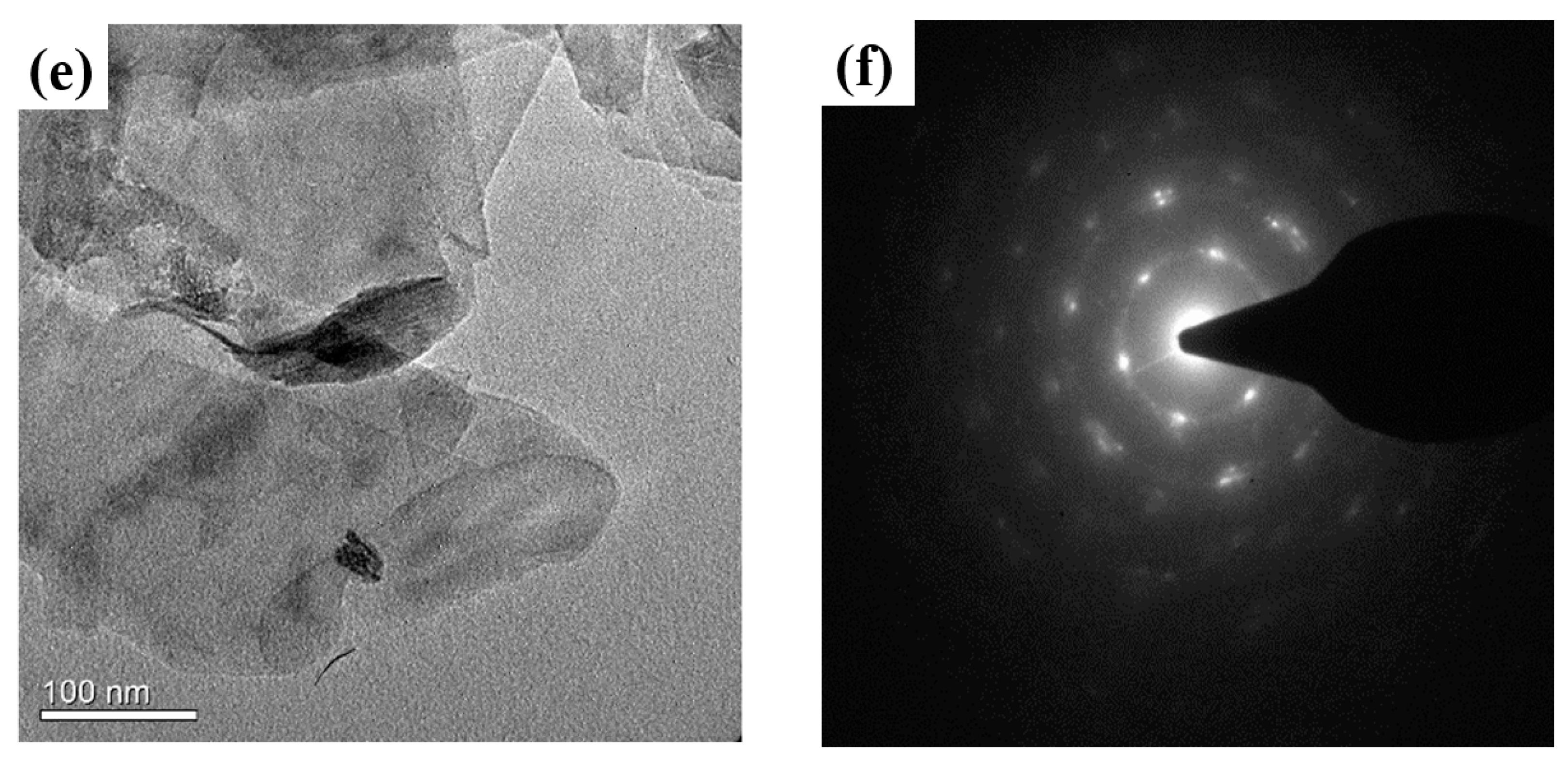
4.1. Morphology Measurement of the Supercritical CO2 Exfoliated GNFs
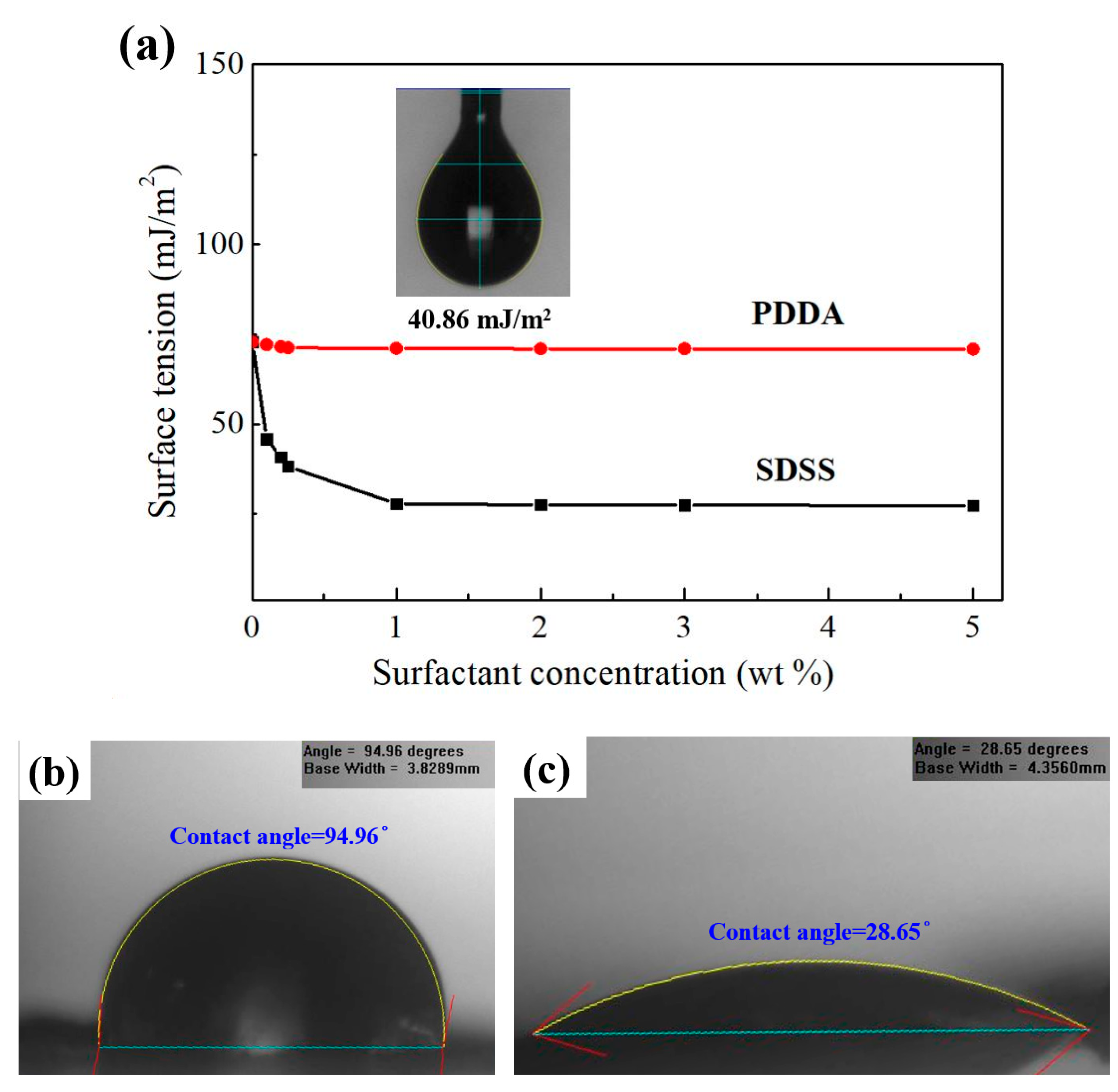
4.2. Effect of Surfactants on the Dispersibility of Carbon Nanomaterials
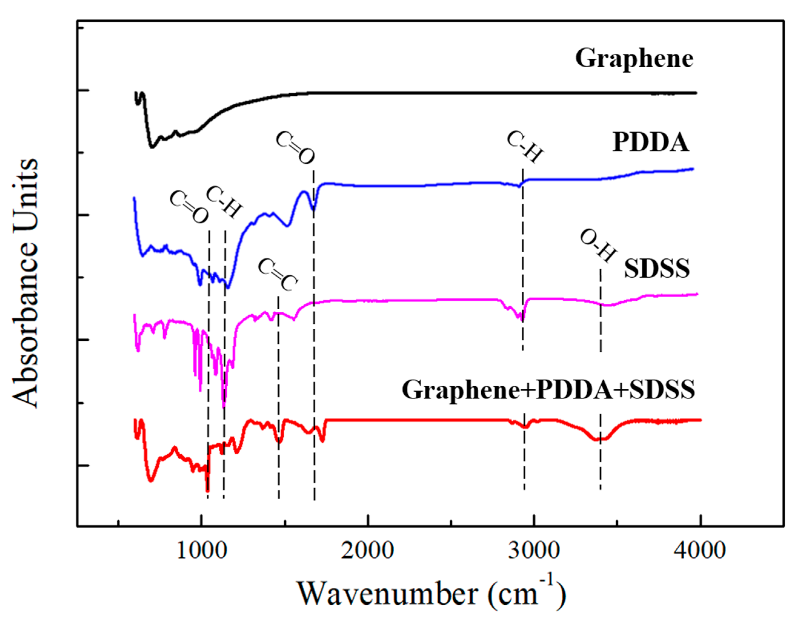
4.3. Characteristic Analysis of the Heat Dissipation Coatings
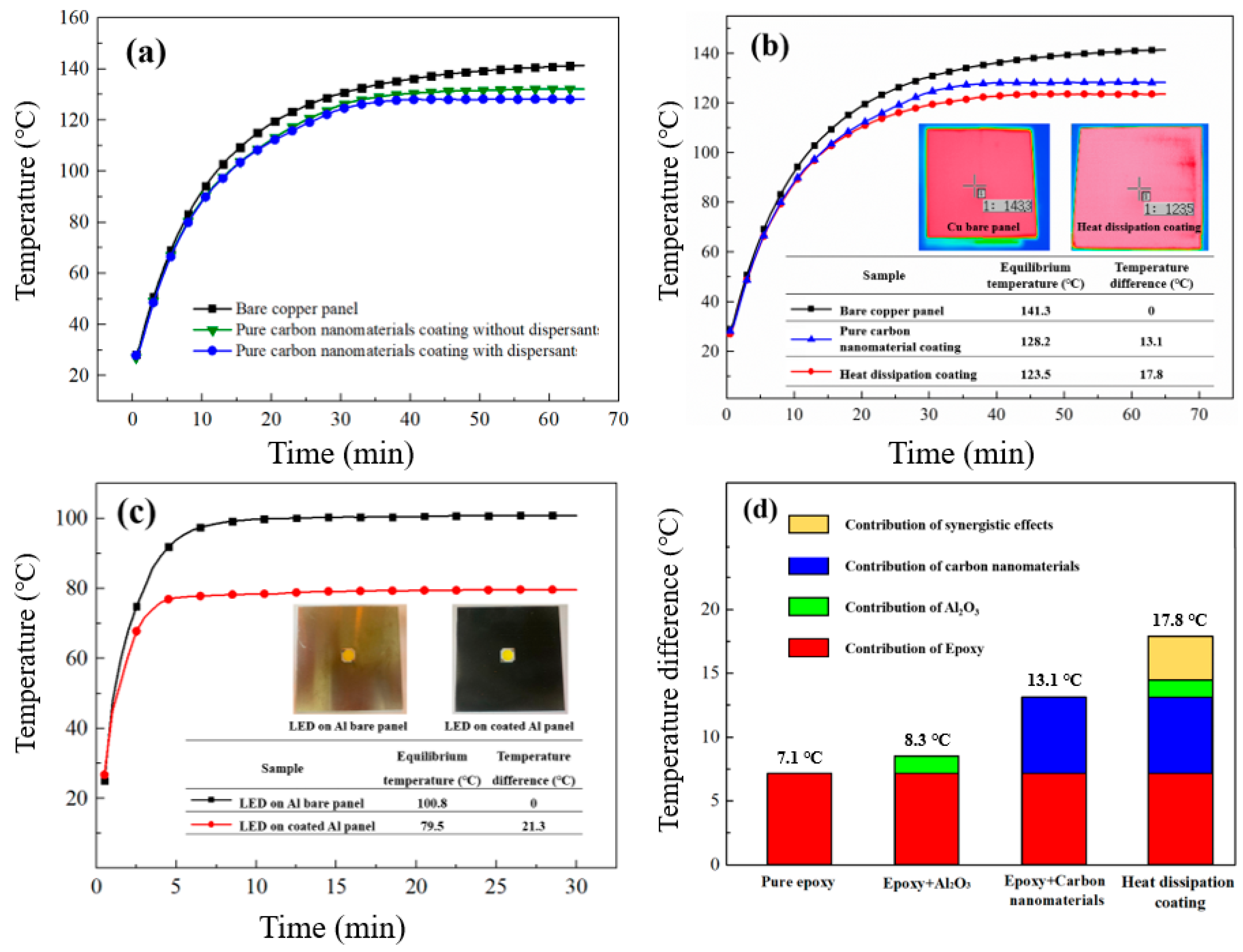
4.4. Characteristic Analysis of the Heat Dissipation Coatings
5. Conclusions
Supplementary Materials
Author Contributions
Funding
Data Availability Statement
Acknowledgments
Conflicts of Interest
References
- Moore, A.L.; Shi, L. Emerging challenges and materials for thermal management of electronics. Mater. Today 2014, 17, 163–174. [Google Scholar] [CrossRef]
- Suryawanshi, C.N.; Lin, C.-T. Radiative Cooling: Lattice Quantization and Surface Emissivity in Thin Coatings. ACS Appl. Mater. Interfaces 2009, 1, 1334–1338. [Google Scholar] [CrossRef] [PubMed]
- Liu, P.; Fan, Z.; Mikhalchan, A.; Tran, T.Q.; Jewell, D.; Duong, H.M.; Marconnet, A.M. Continuous Carbon Nanotube-Based Fibers and Films for Applications Requiring Enhanced Heat Dissipation. ACS Appl. Mater. Interfaces 2016, 8, 17461–17471. [Google Scholar] [CrossRef] [PubMed]
- Sun, J.; Zhuang, J.; Jiang, H.; Huang, Y.; Zheng, X.; Liu, Y.; Wu, D. Thermal dissipation performance of metal-polymer com-posite heat exchanger with V-shape microgrooves: A numerical and experimental study. Appl. Therm. Eng. 2017, 121, 492–500. [Google Scholar] [CrossRef]
- Jha, V.K.; Bhaumik, S.K. Enhanced heat dissipation in helically finned heat sink through swirl effects in free convection. Int. J. Heat Mass Transf. 2019, 138, 889–902. [Google Scholar] [CrossRef]
- Luo, Q.; Li, P.; Cai, L.; Chen, X.; Yan, H.; Zhu, H.; Zhai, P.; Li, P.; Zhang, Q. Experimental investigation on the heat dissipa-tion performance of flared-fin heat sinks for concentration photovoltaic modules. Appl. Therm. Eng. 2019, 157, 113666. [Google Scholar] [CrossRef]
- Qiu, T.; Wen, D.; Hong, W.; Liu, Y. Heat transfer performance of a porous copper micro-channel heat sink. J. Therm. Anal. 2020, 139, 1453–1462. [Google Scholar] [CrossRef]
- Khattak, Z.; Ali, H.M. Air cooled heat sink geometries subjected to forced flow: A critical review. Int. J. Heat Mass Transf. 2019, 130, 141–161. [Google Scholar] [CrossRef]
- Chen, L.; Yang, A.; Feng, H.; Ge, Y.; Xia, S. Constructal design progress for eight types of heat sinks. Sci. China Technol. Sci. 2020, 63, 879–911. [Google Scholar] [CrossRef]
- Li, H.; Fu, S.; Li, G.; Fu, T.; Zhou, R.; Tang, Y.; Tang, B.; Deng, Y.; Zhou, G. Effect of fabrication parameters on capillary pumping performance of multi-scale composite porous wicks for loop heat pipe. Appl. Therm. Eng. 2018, 143, 621–629. [Google Scholar] [CrossRef]
- Huang, G.; Liu, W.; Luo, Y.; Li, Y. A novel ultra-thin vapor chamber for heat dissipation in ultra-thin portable electronic devices. Appl. Therm. Eng. 2020, 167, 114726–114736. [Google Scholar] [CrossRef]
- Wu, F.; Ze, H.; Chen, S.; Gao, X. High-Efficiency Boiling Heat Transfer Interfaces Composed of Electroplated Copper Nanocone Cores and Low-Thermal-Conductivity Nickel Nanocone Coverings. ACS Appl. Mater. Interfaces 2020, 12, 39902–39909. [Google Scholar] [CrossRef] [PubMed]
- Lee, D.H.; Lee, H.K.; Yu, J.S.; Bae, S.J.; Choi, J.H.; Kim, D.H.; Ju, I.C.; Song, K.M.; Kim, J.M.; Shin, C.S. Temperature and thermal characteristics of InGaN/GaN vertical light-emitting diodes on electroplated copper. Semicond. Sci. Technol. 2011, 26, 055014–055022. [Google Scholar] [CrossRef]
- Xie, Y.; Lai, Q.; Guo, P.; Tan, J. Investigating the infrared spectral radiative properties of self-ordered anodic aluminum oxide for passive radiative heat dissipation. Infrared Phys. Technol. 2020, 109, 103438. [Google Scholar] [CrossRef]
- Lee, J.; Kim, D.; Choi, C.-H.; Chung, W. Nanoporous anodic alumina oxide layer and its sealing for the enhancement of radiative heat dissipation of aluminum alloy. Nano Energy 2017, 31, 504–513. [Google Scholar] [CrossRef]
- Kim, Y.; Kim, M.; Seong, H.-G.; Jung, J.-Y.; Baeck, S.-H.; Shim, S.-E. Roles of silica-coated layer on graphite for thermal conductivity, heat dissipation, thermal stability, and electrical resistivity of polymer composites. Polymer 2018, 148, 295–302. [Google Scholar] [CrossRef]
- Zou, Y.; Wang, Y.; Xu, S.; Jin, T.; Wei, D.; Ouyang, J.; Jia, D.; Zhou, Y. Super hydrophobic double-layer coating for efficient heat dissipation and corrosion protection. Chem. Eng. J. 2019, 362, 638–649. [Google Scholar] [CrossRef]
- Fan, D.; Jin, M.; Wang, J.; Liu, J.; Li, Q. Enhanced heat dissipation in graphite-silver-polyimide structure for electronic cooling. Appl. Therm. Eng. 2020, 168, 114676. [Google Scholar] [CrossRef]
- Hu, B.; Li, X.; Fu, Y.; Zhang, F.; Gu, C.; Ren, X.; Wang, C. Experimental investigation on the flow and flow-rotor heat transfer in a rotor-stator spinning disk reactor. Appl. Therm. Eng. 2019, 162, 114316. [Google Scholar] [CrossRef]
- Chan, K.; Tso, C.; Hussain, A.; Chao, C.Y. A theoretical model for the effective thermal conductivity of graphene coated metal foams. Appl. Therm. Eng. 2019, 161, 114112–114122. [Google Scholar] [CrossRef]
- Zou, Y.; Wang, Y.; Wei, D.; Ge, Y.; Ouyang, J.-H.; Jia, D.; Zhou, Y. Facile One-Step Fabrication of Multilayer Nanocomposite Coating for Radiative Heat Dissipation. ACS Appl. Electron. Mater. 2019, 1, 1527–1537. [Google Scholar] [CrossRef]
- Chen, P.-H.; Lin, C.-L.; Liu, Y.-K.; Chung, T.-Y.; Liu, C.-Y. Diamond heat spreader layer for high-power thin-GaN light-emitting diodes. IEEE Photonics Technol. Lett. 2008, 20, 845–847. [Google Scholar] [CrossRef]
- Hsiao, T.-J.; Eyassu, T.; Henderson, K.; Kim, T.; Lin, C.-T. Monolayer graphene dispersion and radiative cooling for high power LED. Nanotechnology 2013, 24, 395401. [Google Scholar] [CrossRef] [PubMed]
- Eyassu, T.; Hsiao, T.-J.; Henderson, K.; Kim, T.; Lin, C.-T. Molecular Cooling Fan: Factors for Optimization of Heat Dissipation Devices and Applications. Ind. Eng. Chem. Res. 2014, 53, 19550–19558. [Google Scholar] [CrossRef]
- Lin, C.-T. MOLECULAR FAN. United States Patent US 7,931,969 B2, 26 April 2011. [Google Scholar]
- Lin, C.-T. MOLECULAR FAN. United States Patent US 8,545,933 B2, 1 October 2013. [Google Scholar]
- Hong, S.; Yoo, S.-S.; Yoo, P.-J. Binder-free heat dissipation films assembled with reduced graphene oxide and alumina nanoparticles for simultaneous high in-plane and cross-plane thermal conductivities. J. Mater. Chem. C. 2019, 7, 9380–9388. [Google Scholar] [CrossRef]
- Pak, S.Y.; Kim, H.M.; Kim, S.Y.; Youn, J.R. Synergistic improvement of thermal conductivity of thermoplastic composites with mixed boron nitride and multi-walled carbon nanotube fillers. Carbon 2012, 50, 4830–4838. [Google Scholar] [CrossRef]
- Leung, S.-N.; Khan, M.-O.; Chan, E.; Naguib, H.-E.; Dawson, F.; Adinkrah, V.; Lakatos-Hayward, L. Synergistic effects of hybrid fillers on the development of thermally conductive polyphenylene sulfide composites. J. Appl. Polym. Sci. 2013, 127, 3293–3301. [Google Scholar] [CrossRef]
- Chen, H.; Ginzburg, V.V.; Yang, J.; Yang, Y.; Liu, W.; Huang, Y.; Du, L.; Chen, B. Thermal conductivity of polymer-based composites: Fundamentals and applications. Prog. Polym. Sci. 2016, 59, 41–85. [Google Scholar] [CrossRef]
- Cheng, X.; Liang, X. Entransy flux of thermal radiation and its application to enclosures with opaque surfaces. Int. J. Heat Mass Transf. 2011, 54, 269–278. [Google Scholar] [CrossRef]
- Motevali, A.; Minaei, S.; Khoshtagaza, M.H. Evaluation of energy consumption in different drying methods. Energy Convers. Manag. 2011, 52, 1192–1199. [Google Scholar] [CrossRef]
- Roos, A.; Chibuye, T.; Karlsson, B. Properties of oxidized copper surfaces for solar applications I. Sol. Energy Mater. Sol. Cells 1983, 7, 453–465. [Google Scholar] [CrossRef]
- Ayán-Varela, M.; Paredes, J.; Villar-Rodil, S.; Rozada, R.; Martínez-Alonso, A.; Tascón, J. A quantitative analysis of the dispersion behavior of reduced graphene oxide in solvents. Carbon 2014, 75, 390–400. [Google Scholar] [CrossRef]
- Nayak, L.; Mohanty, S.; Ramadoss, A. A green approach to water-based graphene ink with reverse coffee ring effect. J. Mater. Sci. Mater. Electron. 2021, 32, 7431–7442. [Google Scholar] [CrossRef]
- Shabafrooz, V.; Bandla, S.; Hanan, J.C. Graphene dispersion in a surfactant-free, polar solvent. J. Mater. Sci. 2018, 53, 559–572. [Google Scholar] [CrossRef]
- Hildebrand, J.-H.; Prausnitz, J.-M.; Scott, R.-L. Regular and Related Solutions: The Solubility of Gases, Liquids, and Solids, 1st ed.; Van Nostrand Reinhold Company: New York, NY, USA, 1970. [Google Scholar]
- Narayan, R.; Kim, S.O. Surfactant mediated liquid phase exfoliation of graphene. Nano Converg. 2015, 2, 20–39. [Google Scholar] [CrossRef] [PubMed] [Green Version]
- Hernandez, Y.; Nicolosi, V.; Lotya, M.; Blighe, F.M.; Sun, Z.; De, S.; McGovern, I.T.; Holland, B.; Byrne, M.; Gun’Ko, Y.K.; et al. High-yield production of graphene by liquid-phase exfoliation of graphite. Nat. Nanotechnol. 2008, 3, 563–568. [Google Scholar] [CrossRef] [Green Version]
- Liu, J.; Fu, J.; Yang, Y.; Gu, C. Study on dispersion, mechanical and microstructure properties of cement paste incorporating graphene sheets. Constr. Build. Mater. 2019, 199, 1–11. [Google Scholar] [CrossRef]
- Yeon, C.; Yun, S.J.; Lee, K.-S.; Lim, J.W. High-yield graphene exfoliation using sodium dodecyl sulfate accompanied by alcohols as surface-tension-reducing agents in aqueous solution. Carbon 2015, 83, 136–143. [Google Scholar] [CrossRef]
- Ma, H.; Li, S.; Zhang, H.; Wei, Y.; Jiang, L. Fabrication of polydopamine-based layer-by-layer nanocomposites for combined pH-sensitive chemotherapy and photothermal therapy. Colloid Surf. A-Physicochem. Eng. Asp. 2019, 561, 332–340. [Google Scholar] [CrossRef]
- Poorsargol, M.; Alimohammadian, M.; Sohrabi, B.; Dehestani, M. Dispersion of graphene using surfactant mixtures: Exper-imental and molecular dynamics simulation studies. Appl. Surf. Sci. 2019, 464, 440–450. [Google Scholar] [CrossRef]
- So, K.P.; Jeong, J.C.; Gil Park, J.; Park, H.K.; Choi, Y.H.; Noh, D.H.; Keum, D.H.; Jeong, H.Y.; Biswas, C.; Hong, C.H.; et al. SiC formation on carbon nanotube surface for improving wettability with aluminum. Compos. Sci. Technol. 2012, 74, 6–13. [Google Scholar] [CrossRef]
- Sim, H.-S.; Kim, T.-A.; Lee, K.-H.; Park, M. Preparation of graphene nanosheets through repeated supercritical carbon diox-ide process. Mater. Lett. 2012, 89, 343–346. [Google Scholar] [CrossRef]
- Liu, C.; Hu, G.; Gao, H. Preparation of few-layer and single-layer graphene by exfoliation of expandable graphite in super-critical N,N-dimethylformamide. J. Fluid Mech. 2012, 63, 99–104. [Google Scholar]
- Tiwari, S.K.; Huczko, A.; Oraon, R.; De Adhikari, A.; Nayak, G.C. Facile electrochemical synthesis of few layered graphene from discharged battery electrode and its application for energy storage. Arab. J. Chem. 2017, 10, 556–565. [Google Scholar] [CrossRef] [Green Version]
- Pu, N.-W.; Wang, C.-A.; Sung, Y.; Liu, Y.-M.; Ger, M.-D. Production of few-layer graphene by supercritical CO2 exfoliation of graphite. Mater. Lett. 2009, 63, 1987–1989. [Google Scholar] [CrossRef]
- Gao, Y.; Shi, W.; Wang, W.; Wang, Y.; Zhao, Y.; Lei, Z.; Miao, R. Ultrasonic-Assisted Production of Graphene with High Yield in Supercritical CO2 and Its High Electrical Conductivity Film. Ind. Eng. Chem. Res. 2014, 53, 2839–2845. [Google Scholar] [CrossRef]
- Yu, W.; Xie, H.; Yin, L.; Zhao, J.; Xia, L.; Chen, L. Exceptionally high thermal conductivity of thermal grease: Synergistic effects of graphene and alumina. Int. J. Therm. Sci. 2015, 91, 76–82. [Google Scholar] [CrossRef]
- Kim, S.; Jeong, J.Y.; Han, S.H.; Kim, J.H.; Kwon, K.T.; Hwang, M.K.; Kim, I.T.; Cho, G.S. Effect of thermal dissipation by adding graphene materials to surface coating of LED lighting module. J. Nanosci. Nanotechnol. 2013, 13, 3554–3558. [Google Scholar] [CrossRef]


| Types of coatings | IR Emissivity |
|---|---|
| Pure epoxy | 0.93 |
| Epoxy+30 wt% Al2O3 | 0.92 |
| Epoxy+2 wt% GNFs+2 wt% MWCNTs | 0.98 |
| Epoxy+30 wt% Al2O3+2 wt% GNFs+2 wt% MWCNTs | 0.96 |
| Matrix Polymer | Carbon Materials | Filler Particles | Added Surfactants | Infrared Emissivity | ΔT (°C) | Ref. |
|---|---|---|---|---|---|---|
| PTEE *1 | Graphite powder | Silica | Triton X-100 *2 PEG *3 | - | 9 | [22] |
| Acrylate | Nano diamond powder | - | FS-510 *4 PTFE *5 | - | 9 | [2] |
| Carbon black | 11 | |||||
| MWCNTs | 13 | |||||
| Acrylic copolymer | Graphene | - | FS-510 PTFE SDBS *6 | 0.99 | 16 | [23] |
| Acrylic copolymer | MWCNTs | - | SDBS | 0.98 | 14 | [24] |
| Graphene nano-platelets | Alumina | - | 0.9 | 11 | [51] | |
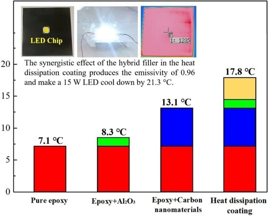
| Water-based epoxy | GNFs MWCNTs | Spherical alumina | SDSS *7 PDDA *8 | 0.96 | 17.8 | This study |
Publisher’s Note: MDPI stays neutral with regard to jurisdictional claims in published maps and institutional affiliations. |
© 2022 by the authors. Licensee MDPI, Basel, Switzerland. This article is an open access article distributed under the terms and conditions of the Creative Commons Attribution (CC BY) license (https://creativecommons.org/licenses/by/4.0/).
Share and Cite
Cheng, C.; Shi, W.-H.; Teng, T.-P.; Yang, C.-R. Evaluation of Surfactants on Graphene Dispersion and Thermal Performance for Heat Dissipation Coating. Polymers 2022, 14, 952. https://doi.org/10.3390/polym14050952
Cheng C, Shi W-H, Teng T-P, Yang C-R. Evaluation of Surfactants on Graphene Dispersion and Thermal Performance for Heat Dissipation Coating. Polymers. 2022; 14(5):952. https://doi.org/10.3390/polym14050952
Chicago/Turabian StyleCheng, Chia, Wen-Hao Shi, Tun-Ping Teng, and Chii-Rong Yang. 2022. "Evaluation of Surfactants on Graphene Dispersion and Thermal Performance for Heat Dissipation Coating" Polymers 14, no. 5: 952. https://doi.org/10.3390/polym14050952
APA StyleCheng, C., Shi, W.-H., Teng, T.-P., & Yang, C.-R. (2022). Evaluation of Surfactants on Graphene Dispersion and Thermal Performance for Heat Dissipation Coating. Polymers, 14(5), 952. https://doi.org/10.3390/polym14050952