Article

Ballistic Limit of UHMWPE Composite Armor under Impact of Ogive-Nose Projectile

1
School of Mechanical Engineering, Nanjing University of Science and Technology, Nanjing 210094, China
2
Nanjing Changjiang Electronics Group Co., Ltd., Nanjing 210037, China
*
Author to whom correspondence should be addressed.
Polymers 2022, 14(22), 4866; https://doi.org/10.3390/polym14224866
Submission received: 13 October 2022 / Revised: 7 November 2022 / Accepted: 8 November 2022 / Published: 11 November 2022

Abstract

:
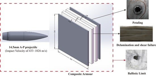
The ballistic response of armor has been widely used to evaluate its feasibility and advantages as a protective structure. To obtain the ballistic performance and ballistic limitations of composite armor, a type of ultra–high molecular weight polyethylene (UHMWPE) composite armor is designed, which is composed of UHMWPE laminates and steel face sheets of Q235. The total thickness of the armor is 53 mm, with an in–plane dimension of 300 mm × 300 mm. Then, an experimental study of the ballistic impact response of composite armor subject to a typical ogive–nose projectile was carried out. In the velocity range of 501.1 to 1026.1 m/s, the 14.5 mm caliber armor–piercing projectile could penetrate through the composite armor. At the velocity of 433.3 m/s, the A–P projectile was embedded in the armor, leaving a bulge mark on the back sheet. Therefore, 467.2 m/s is taken as the ballistic limit of the armor under the impact of the ogive–nose projectile. In addition, a corresponding numerical simulation model is also established to predict the ballistic limit of the projectile. The numerical predictions are consistent with the experimental results. The ballistic limit obtained from the numerical simulation results is 500 m/s, which is acceptable with a relative error of 7.02%. The failure mechanism of the composite armor is also obtained. Petaling is the main dominant failure mode for both face sheets, while delamination and shear failure dominate the penetration process of UHMWPE laminates. Finally, the perforation mechanism of composite armor under the impact of an A–P projectile is analyzed with theoretical models to predict the residual velocity, the work performed during the perforation, and the resisting stress of σs in the cavity–expansion model. The experimental and numerical simulation results can provide necessary data in the analysis of the composite structure’s dynamic response under the impact of sharp head penetrators. The research results present the ballistic performance, failure mechanism, and ballistic limit of the composite armor under the impact of a typical ogive–nose projectile, which can be significant in the design of composite armor in the areas of ship shield, fortifications protection, and bulletproof structures against threats from sharp head penetrators.

Graphical Abstract

1. Introduction

Multilayered armor systems have been widely used in numerous ballistic and bulletproof applications, including bulletproof helmets, vests, and other armor parts, providing an acceptable range of protection for soldiers and structures [1,2,3,4,5,6]. Due to the advantages of high stiffness and low density, composites reinforced with ultra–high molecular weight polyethylene (UHMWPE) fibers are increasingly being used in the field of national defense as parts of lightweight armor systems to protect fortifications and structures from ballistic impacts [7,8,9]. The ballistic performance of monolithic UHMWPE composite under the impact of a blunt projectile has been studied [10,11,12,13,14], and the failure mechanisms analyzed. A common design of composite armor is a sandwich structure, which is made of thin face sheets and low–density non–metal cores. In addition, the ballistic impact response of a sandwich structure consisting of UHMWPE under a blunt projectile has also been investigated [15,16,17,18,19]. Deflection and bulging [4] consisting of shear plugging, formation of a transition plane, and bulging are the failure modes of UHMWPE [11], which allow it to have an excellent ability to resist the penetration of blunt projectiles.
It is reported that the bulletproof properties of composite materials are greatly discounted under the ballistic impact of projectiles with a sharp head [17,20,21]. However, little is reported on the ballistic performance of the UHMWPE or composite armors containing UHMWPE laminates under the impact of sharp head projectiles. Whether the ballistic performance of the composite armor can be predicted using numerical simulation has not been discussed yet. In addition, to evaluate the resistance of composite armors, especially with the sandwich structure containing UHMWPE laminates, the failure mode and failure mechanism of UHMWPE should also be further studied. An experimental study is one of the basic methods of scientific research, which provides the most direct evidence to help understand physical phenomena. However, the penetration process of the ballistic impact can hardly be observed in experiments. Therefore, due to the limits of testing conditions and the costs of the investment, it is difficult to carry out the relevant research that depends on experiments. Numerical simulations are similar to experimental research that is based on theoretical research [10,14,22]; they are efficient but irrelevant in external conditions. With the help of computer realization, the laws of penetration and dynamic response of the target can be obtained with accurate simulation models. The intermediate process in the penetration process could also be observed, and the crucial parameters could be extracted in the post–processing section to help understand the mechanism of the physical experiment better.
In this paper, a sandwich structure of UHMWPE composite armor is designed, which is made of two pieces of UHMWPE laminates in the middle and Q235 steel face sheets. The ballistic performance of the composite armor is studied systematically both from experiment and numerical simulation. The ballistic limit of UHMWPE composite armor under the impact of an ogive–nose penetrator is obtained, and the failure mechanism of the armor is analyzed. Finally, typical theoretical models are used to predict the residual velocity, the work performed during the perforation, and the resisting stress of σs in the cavity–expansion model to help better understand the penetration process of the composite armor under the impact of sharp head projectiles.

2. Configuration of the Armor and Projectile

2.1. Design of the Armor

As shown in Figure 1, the UHMWPE composite armor is made up of two pieces of UHMWPE laminates in the middle and Q235 steel face sheets. Typical UHMWPE laminate with a material grade of FDB4-HW-S1 is selected. Each piece of UHMWPE laminate has a thickness of 20 mm, and each Q235 steel face sheet has a thickness of 6 mm. Each layer of armor has the same in–plane dimensions of 300 mm × 300 mm, with a total thickness of 52 mm. The thin binder layer is replaced in each panel, then followed by pressing to obtain the overall panel structure of the composite armor. Due to the existence of a binder layer, the total thickness of the composite armor may increase from 1 mm to 53 mm.
The material properties of Q235 steel are presented in Table 1, which is provided by the manufacturer of Wuhan Iron & Steel Co., Ltd., Wuhan, China.

2.2. Structure of the Projectile

The structure of the standard Chinese projectile of 14.5 mm caliber armor–piercing (A–P) projectile is shown in Figure 2. The main geometric parameters of the projectile are presented in Figure 2a, with a total diameter of 14.93 mm and a length of 66.7 mm. The projectile is mainly composed of the brass jacket, steel core, and lead filler. The steel core with an ogive–nose head is made of a non–deformable hardened steel core, which will mainly contribute to the penetration performance of the projectile. The A–P core has a diameter of 12.48 mm and a length of 53.4 mm, with a mass of 40.2 to 41 g. Generally, the jacket is made of gliding brass, and the filler is made of lead, which serves to protect the barrel from the core, enhance the sealing effect and provide an optimized shape for flight in the air. They have a relatively small effect during the penetration, and they are not modeled in the following numerical simulation [23,24,25].
The ballistic limit or limit velocity is the velocity required for a particular projectile to reliably penetrate a particular piece of material. In other words, a given projectile will not pierce a given target when the projectile velocity is lower than the ballistic limit [26]. In addition, it is also important to evaluate the resistance of the armor. Due to the unknown perforation mechanism and the unknown ballistic limit of composite armor under the ballistic impact, especially the sharply pointed projectile, an experiment of the UHMWPE composite armor under the ballistic impact of the A–P projectile was carried out first.

3. Experimental Details and Results

3.1. Design of the Experiment

Figure 3 shows the 14.5 mm caliber A–P projectile and the state of the assembly of the projectile in the cartridge. By adjusting the quantity of the propellent in the cartridge, the pre–set velocities of the A–P projectile can be acquired.
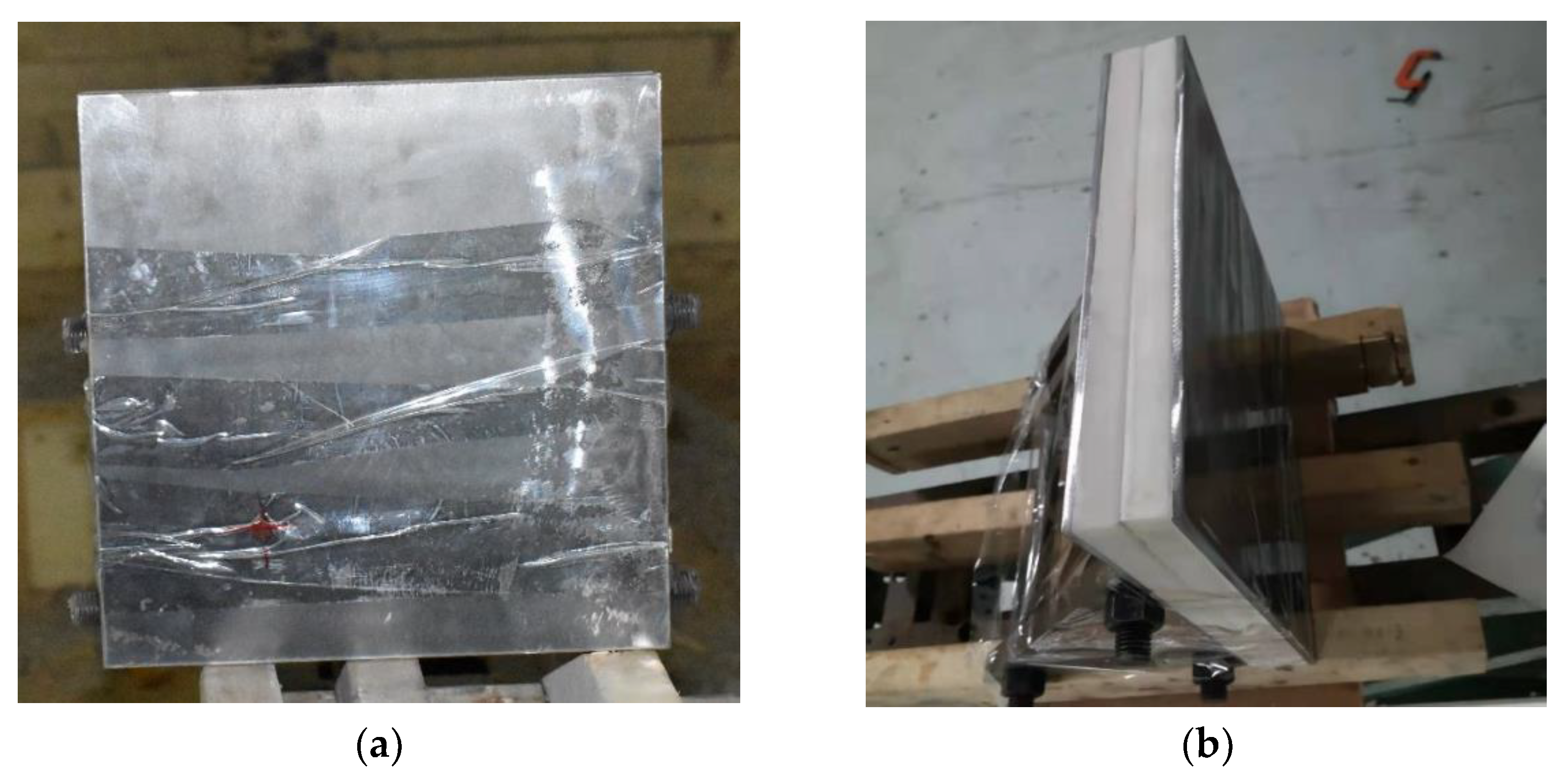
Figure 4 shows the states of the composite armors used in the experiment. The armors were clamped to the rear base on the steel shelf. The rear base was a triangle–shaped bracket, which was fixed to the steel shelf with bundles of iron wire. Figure 5 presents the electronic time–measuring instrument with six channels to capture the signal when the penetrator perforates through the tinfoil target. The electronic time–measuring instrument is of high sensitivity and is able to record the minimum time difference of 1 μs. The layout of the ballistic impact experiment is presented in Figure 6. The 14.5 mm caliber smooth–bore gun was mounted on a rigid platform. The distance between the gun muzzle and armor is about 4 m. To measure the impact velocity of the projectile, two tinfoil targets were placed in front of the armor. The composite armor was placed on a steel shelf at the same height as the ballistic gun.

3.2. Experimental Results

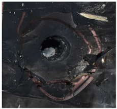
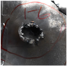
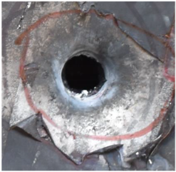
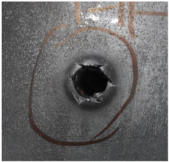
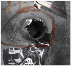
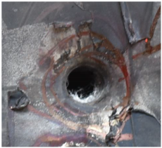
The perforation results of composite armor by the A–P projectile are listed in Table 2. For the unknown perforation mechanism and the unknown ballistic limit of composite armor under the ballistic impact of the sharply pointed projectile especially, the impact velocities vi of the ogive–nose projectile were set at 1026 m/s initially to much lower velocities. In the velocity range of 501.1 to 1026.1 m/s, the A–P projectile could penetrate through the composite armor. While at the velocity of 433.3 m/s, the A–P projectile was embedded in the armor, leaving a bulge mark on the back sheet. The diameter of the entrance hole on the front sheet was about 14–16 mm, while the diameter of the outlet on the back sheet was about 13–24 mm. The entrance dimension discrepancies are small on the front sheet, and the divergence increased with the increase in impact velocity.
Figure 7 shows the state of a stripped brass jacket and lead filler. Figure 7a,c shows the front and back views of the perforation on the front sheet at the velocity of 524.8 m/s, and Figure 7b,d shows the front and back views of the perforation at the velocity of 501.1 m/s. The ablative phenomenon can be observed, especially on the back view of the front sheet, resulting from a severe interaction during the penetration.
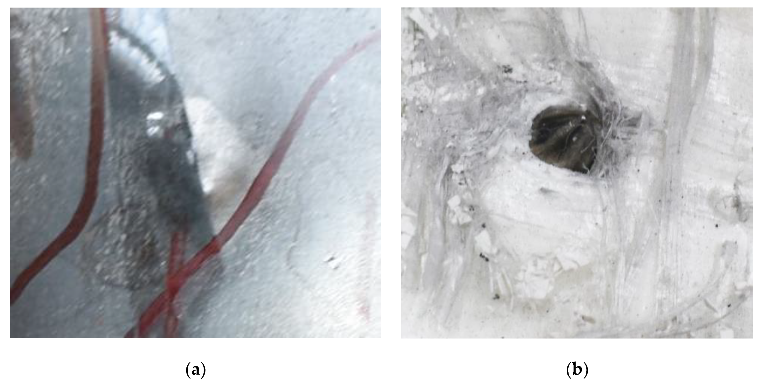
Figure 8 shows the failure states of the PE laminates. As shown in Figure 8a, in the side view of the PE laminates, the obvious phenomenon of delamination can be observed. As presented in Figure 8b, a penetration cavity was formed by the ogive–nose penetrator with relatively neat cutting edges accompanied by a charring layer. In addition, the PE laminate exhibited an extent of fibrillation, and the bare bunches of fibers can be observed around the penetration hole.
Figure 9 presents additional detail on the perforation results at the impact velocity of 433.3 m/s, with the penetrator embedded in the armor. An obvious indentation was formed on the back of the back sheet, as shown in Figure 9a. After the back sheet was removed, the head of the steel core of the A–P projectile can be seen in Figure 9b, accompanied by an extent of fibrillation.
Regarding the results of Table 2 and Figure 7, Figure 8 and Figure 9, it can be summarized from the perforation results that: (1) The average velocities of 501.1 m/s and 433.3 m/s can be taken as the ballistic limits of the UHMWPE composite armor under the impact of the ogive–nose penetrator at 467.2 m/s. (2) Petaling, as the main dominant failure mode for both face sheets, can be observed within the range of impact velocity of 501 m/s to 1026 m/s. The surface of both face sheets stays relatively flat, with small overall deformation except for the protruding petal–shaped holes. Small pieces of petals accompanied by gaped rifts formed the perforation. (3) Delamination and shear failure dominate the penetration process of UHMWPE laminates. Due to the low interlaminar stiffness and strength in the PE laminate, delamination is prevalent through the panel’s thickness, as can be seen in Figure 10a. (4) The charring layer on the front steel plate can be observed, and more severe ablation could be noticed at the impact velocity of around 1000 m/s.

4. Numerical Simulation and Analysis

4.1. Setup of Numerical Model

To predict the dynamic response and obtain the ballistic limit of UHMWPE composite armor under the ballistic impact of the A–P core, three–dimensional numerical models are carried out using the AUTODYN nonlinear software. The version of AUTODYN is v11.0 in the software of ANSYS 11.0, located in Nanjing, China.
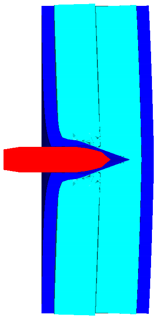
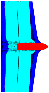
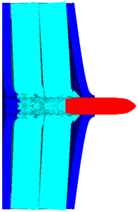
As shown in Figure 10, the 3D Lagrange algorithm is adopted for all of the components in numerical simulation. The half 3D model is carried out with a mesh size of about 1.2 mm per grid. A hexahedral structured grid is used to model both the projectile and the composite armor. The numerical simulation model is composed of about 810 thousand nodes and 800 elements. On the edge of the target, fixed boundaries are used to constrain the movement of the armor. The boundary conditions are applied on the edges of both the face and back sheets. Different initial velocities are applied to the ogive–nose head penetrator to simulate the dynamic penetration behavior with different impact velocities. The material models and the parameters will be described below.
As presented in Table 3, the material models for the penetrator, face sheet, and UHMWPE laminate are listed. For steel, the shock equation of state, also called Grüneisen, is employed in conjunction with the Johnson–Cook constitutive model to simulate the dynamic response under ballistic impact. The Grüneisen EOS [27] can be used to describe how the materials interact with the shock wave and are based on Hugoniot’s relation between the vs. and the vp, as vs = c0 + svp, where vs. is the shock wave velocity, vp is the material particle velocity, c0 is the wave speed, and s is a material–related coefficient. The expression of the equation of state of Grüneisen for the compressed state is:
p = ρ 0 C 2 μ [ 1 + ( 1 γ 0 2 ) μ a 2 μ 2 ] [ 1 ( S 1 1 ) μ S 2 μ 2 μ + 1 S 3 μ 3 ( μ + 1 ) 2 ] + ( γ 0 + a μ ) E .
In the expanded state,
p = ρ 0 C 2 μ + ( γ 0 + a μ ) E
where C is the intercept of the velocity curve between the shock wave and particle; S1, S2, and S3 represent the slope of the vsvp curve; γ0 is the coefficient of the Grüneisen; a is the one–order correction of γ0. μ = ρ/ρ0 − 1 is a non–dimensional coefficient based on initial and instantaneous material densities. The parameters of the Grüneisen equation of state are listed in Table 4.
The Johnson–Cook model [28,29] incorporates the effect of strain rate–dependent work hardening and thermal softening, which is given by:
σ = ( A + B ε n ) ( 1 + C ln ε ˙ ε ˙ 0 ) ( 1 T m )
where ε is the plastic strain, and the temperature factor is expressed as:
T = T T r T m T r
where Tr is the room temperature, and Tm is the melt temperature of the material. A, B, n, C, and m are material–related parameters. The material parameters of S-7 tool steel and Q235 steel are presented in Table 5.
The orthotropic material model proposed by Long H. Nguyen et al. [14] was used for modeling the dynamic behavior of the UHMWPE layer subjected to ballistic impact. The material models consist of a nonlinear equation of the state of orthotropic, a strength model, and a failure model. The constitutive response of the material in the elastic regime is described as the orthotropic EOS composed of volumetric and deviatoric components. The pressure is defined by:
P = P ( ε v o l , e ) 1 3 ( C 11 + C 21 + C 31 ) ε 11 d 1 3 ( C 12 + C 22 + C 32 ) ε 22 d 1 3 ( C 13 + C 23 + C 33 ) ε 33 d
where Cij are the coefficients of the stiffness matrix, ε i j d refers to the deviatoric strains in the principal directions, and the volumetric component P ( ε v o l , e ) is defined by the Mie–Grüneisen EOS:
P ( ε v o l , e ) = P r ( v ) + Γ ( v ) v [ e e r ( v ) ]
where v, e, and Γ(v) represent the volume, internal energy, and the Grüneisen coefficient, respectively. Pr(v) is the reference pressure, and er(v) is the reference internal energy. The quadratic yield surface was adopted as the material strength model to describe the nonlinear, irreversible hardening behavior of the composite laminate:
f ( σ i j ) = a 11 σ 11 2 + a 22 σ 22 2 + a 33 σ 33 2 + 2 a 12 σ 11 σ 22 + 2 a 23 σ 22 σ 33 + 2 a 13 σ 11 σ 33 + 2 a 44 σ 23 2 + 2 a 55 σ 31 2 + 2 a 66 σ 12 2 = k
where aij are the plasticity coefficients, and σij represent the stresses in the principal directions of the material. In addition, the state variable, k, is used to define the border of the yield surface. It is described with a master and stress–effective plastic strain curve defined by ten piecewise points to consider the effect of strain hardening.
In the numerical models, the failure model of the orthotropic material is based on a combined stress criterion given as follows:
( σ i i S i i ( 1 D i i ) ) 2 + ( σ i j S i j ( 1 D i j ) ) 2 + ( σ k i S k i ( 1 D k i ) ) 2 1   for   i , j , k = 1 , 2 , 3
where S is the failure strength in the respective directions of the material, and D is the damage parameter following a linear relationship with stress and strain, as shown below:
D i i = L σ i i , f ε c r 2 G i i , f
where L is the characteristic cell length, εcr refers to the crack strain, and Gii,f presents the fracture energy in the direction of damage.
The constants for the orthotropic equation of state are presented in Table 6, and the parameters for orthotropic yield strength are shown in Table 7.

4.2. Numerical Results and Analysis

Table 8 presents the numerical simulation results of the A–P core penetrating the composite armor. vi and vr are the impacts and residual velocities of the ogive–nose penetrator. p is the depth of penetration. Due to the experimental results, the impact velocity is set from 430 m/s to 700 m/s. With the increased impact velocity, the penetration depth gradually increased. When the impact velocity reached 500 m/s, the ogive–nose penetrator could just perforate the composite armor.
The contour of Von–Mises stress at the impact velocity of 500 m/s is shown in Figure 11. It can be inferred that the maximum stress exceeds the yield stress of the steel plate, and Q235 back plate is pierced. Therefore, the velocity of 500 m/s can be considered as the ballistic limit of the composite armor, which is much higher than the 467.2 m/s obtained from the experimental results. The numerical simulation results are acceptable, with a relative error of 7.02%.

4.3. Perforation Models and Analysis

(1)
Principle of energy conservation
The energy balance for the perforation is given by
1 2 m v i 2 = 1 2 m v r 2 + W
W = W Q 235 + W PE
where m is the mass of the projectile, vi is the impact velocity, vr is the residual velocity, and W is the work performed during perforation. The mass of the A–P core was set at 40.4 g, then the work conducted during the perforation of the composite armor could be calculated, as listed in Table 9. The value of W stayed stable from 5.05 kJ to 5.09 kJ, which means that dissipated energy in the petaling stays stable at around 5 kJ. At the ballistic limit from the numerical results, 500 m/s, the dissipated energy is the same as the work performed at a higher velocity after perforation. So, the principle of energy conservation can be applied here.
(2)
Lambert–Jonas model
The Lambert–Jonas model [26,30,31,32] can provide a reasonable fit to predict the residual velocity of the penetrator after perforation. The model can be expressed as
v r = { 0 , 0 v i v bl α ( v i p v bl p ) 1 / p ,   v i v bl
where vi, vr, and vbl are the impact, residual, and ballistic limit velocity in normal impact. α and p are the coefficients, where 0 ≤ α ≤ 1 and p > 1. Based on the numerical simulation results, the Lambert–Jonas model can be established to predict the residual velocity of the A–P core after perforating the PE composite armor.
When the model with p = 2, the coefficient α can be set as 1, and the model can be justified based on the energy conservation law [33]. This model can be written as
v r = { 0 , 0 v i v bl ( v i 2 v bl 2 ) 1 / 2 ,   v i v bl
the predicted vrvs curve and the simulation results are presented below. As shown in Figure 12, the Lambert–Jonas model can be an effective method in predicting the residual velocity of the A–P core after perforation. In addition, the perforation process can be regarded as a rigid body penetration.
(3)
Cavity–Expansion Model
As the A–P core has a diameter of 12.48 mm and a length of 53.4 mm, the composite armor with a thickness of 53 mm can be considered an intermediate target. The square armor has a width of 300 mm, which is about 24 times the diameter of the A–P core. Thus, the cylindrical cavity expansion can be used to predict the ballistic limit of the A–P core. Figure 13 shows the dimensions of the A–P core. The caliber–radius–head (CRH) is 3.05, which is also denoted as ψ.
Coefficient k1 is expressed as
k 1 = ( 4 ψ 2 4 ψ / 3 + 1 / 3 ) 4 ψ 2 ( 2 ψ 1 ) 4 ψ 1 sin 1 [ 4 ψ 1 2 ψ ]
The radial stress σr at the cavity surface versus cavity expansion velocity V is given by [34]
σ r = σ s + ρ t B V 2
where σs is the quasi–static radial stress required to open the cylindrical cavity, ρt is the density of the target, and B is a dimensionless constant. σs, b, and B are obtained from [23]
σ s = Y 3 { 1 + [ E 3 Y ] n 0 b ( ln x ) n 1 x d x }
b = 1 − γ2
B = 1 2 { 1 ( 1 ν ) 1 α 2 ln [ 1 + 1 α 2 α ] + γ 2 2 ln [ γ ] 1 }  
where Y is, the yield stress and ν is Poisson’s ratio of the target. α and γ are given by
α 2 = 3 ( 1 2 ν ) 2 ( 1 ν ) ( ρ t V 2 Y )
γ 2 = 2 ( 1 + ν ) Y 3 E
Furthermore, a rigid ogive–nosed projectile, with the impact velocity of vi, the ballistic limit of vbl and the residual velocity vr, is given by
v b l = ( 2 σ s ρ p h ( L + k 1 l ) ) 1 / 2 [ 1 + C + 2 3 C 2 ] 1 / 2
v r = v b l [ ( v i v b l ) 2 1 ] 1 / 2 [ 1 C + 1 2 C 2 ] 1 / 2
where C is a small parameter related to the target inertia. When target inertia is neglected, the ballistic limit of vbl and the residual velocity vr can be simplified as [23,25,35] as
v b l = ( 2 σ s ρ p h ( L + k 1 l ) ) 1 / 2
v r = v b l [ ( v i v b l ) 2 1 ] 1 / 2
where the residual velocity vr is the same as the Lambert–Jones model in Equation (13).
Based on the constitutive models of the target materials, the quasi–static radial stress σs can be expressed as [36]
σ s = Y 3 [ 1 + ln ( E 3 Y ) ] + π 2 H 18
where E and H are Young’s modulus and the constant tangent modulus in the plastic region if the stress versus strain curve of the target can be expressed as
σ = { E ε   ,   σ < Y Y + H ε ,   σ Y
Thus, the value of σs for the Q235 face sheets can be calculated. For UHMWPE laminates, there may not be a mature model to predict the quasi–static radial stress required to open the cylindrical cavity, but the range of the σs can be estimated from the empirical formula [37,38] below,
σ s = ( 1.33 ~ 2 ) Y t
When the coefficient is set as the minimum value of 1.33, the value at a relatively low level can be obtained, as listed in Table 10.
For the composite armor composed of Q235 face sheets and UHMWPE laminates, the effective value of σs can range from 2.76 GPa to 4.26 GPa. When the value of effective σs is set as 3.08 GPa, the ballistic limit of the composite armor calculated from Equation (23) is 467 m/s, which is consistent with the value obtained from the numerical simulation results.
In conclusion, the principle of energy conservation and the Lambert–Jonas model can be applied to calculate the work performed during the perforation and the residual velocities of the A–P core after perforation. In addition, the quasi–static radial stress σs required to open the cylindrical cavity can be estimated from the cavity–expansion model. With the value of 3.08 GPa, the predicted ballistic limit is consistent with the numerical simulation results.

5. Conclusions

A UHMWPE composite armor made up of two pieces of UHMWPE laminates in the middle and Q235 steel face sheets is proposed, and a study of the ballistic limit of the composite armor under the impact of a typical ogive–nose penetrator was carried out. (1) According to the experimental results, the average velocity of 501.1 m/s and 433.3 m/s can be taken as the ballistic limit of UHMWPE composite armor under the impact of the ogive–nose projectile, which is 467.2 m/s. In comparison, the ballistic limit obtained from the numerical simulation results was 500 m/s, which is acceptable with a relative error of 7.02%. (2) Petaling, as the main dominant failure mode for both face sheets, could be observed within the impact velocity range of 501 m/s to 1026 m/s. Delamination and shear failure dominated the penetration process of UHMWPE laminates. In addition, the charring layer on the front steel plate could be observed, and more severe ablation could be noticed at the impact velocity of around 1000 m/s. (3) Through theoretical models, the perforation mechanism of composite armor under the impact of A–P cores was analyzed. The principle of energy conservation and the Lambert–Jonas model was applied to calculate the work performed during the perforation and the residual velocities. In addition, the quasi–static radial stress σs required to open the cylindrical cavity were estimated from the cavity–expansion model. With the value of 3.08 GPa, the predicted ballistic limit was consistent with the numerical simulation results.
The ballistic limit of the UHMWPE composite armor under the impact of the ogive–nose projectile was considered to be 467.2 m/s, which indicates that the composite armor may not have a strong ability to resist the penetration of sharp head penetrators. In order to enhance the resistance against bullets such as A–P projectiles, UHMWPE should be strengthened, and the structure should be further optimized in future studies.

Author Contributions

Methodology, validation, formal analysis, writing—original draft preparation, funding acquisition, L.D.; supervision, visualization; writing—review, validation, X.G.; writing—review and editing, supervision, project administration, P.S.; supervision, data curation, resources, X.K. All authors have read and agreed to the published version of the manuscript.

Funding

The authors thank the National Natural Science Foundation of China (Grant No. 11802142) and the project of the State Key Laboratory of Explosion Science and Technology (Grant No. KFJJ20-08M).

Institutional Review Board Statement

The study did not require ethical approval. This statement can be excluded.

Data Availability Statement

The raw and processed data generated during this study will be made available upon reasonable request.

Conflicts of Interest

The authors declare no conflict of interest.

References

  1. Ramadhan, A.; Talib, A.A.; Rafie, A.M.; Zahari, R. High velocity impact response of Kevlar-29/epoxy and 6061-T6 aluminum laminated panels. Mater. Des. 2013, 43, 307–321. [Google Scholar] [CrossRef]
  2. Supian, A.; Sapuan, S.; Jawaid, M.; Zuhri, M.; Ilyas, R.; Syamsir, A. Crashworthiness response of filament wound kenaf/glass fibre-reinforced epoxy composite tubes with influence of stacking sequence under intermediate-velocity impact load. Fibers Polym. 2022, 23, 222–233. [Google Scholar] [CrossRef]
  3. Aisyah, H.; Paridah, M.; Sapuan, S.; Ilyas, R.; Khalina, A.; Nurazzi, N.; Lee, S.; Lee, C. A comprehensive review on advanced sustainable woven natural fibre polymer composites. Polymers 2021, 13, 471. [Google Scholar] [CrossRef]
  4. Suriani, M.; Rapi, H.Z.; Ilyas, R.; Petrů, M.; Sapuan, S. Delamination and manufacturing defects in natural fiber-reinforced hybrid composite: A review. Polymers 2021, 13, 1323. [Google Scholar] [CrossRef] [PubMed]
  5. Nurazzi, N.; Asyraf, M.; Khalina, A.; Abdullah, N.; Aisyah, H.; Rafiqah, S.A.; Sabaruddin, F.; Kamarudin, S.; Norrrahim, M.; Ilyas, R. A review on natural fiber reinforced polymer composite for bullet proof and ballistic applications. Polymers 2021, 13, 646. [Google Scholar] [CrossRef] [PubMed]
  6. Pereira, A.C.; de Assis, F.S.; da Costa Garcia Filho, F.; Oliveira, M.S.; da Cruz Demosthenes, L.C.; Lopera, H.A.C.; Monteiro, S.N. Ballistic performance of multilayered armor with intermediate polyester composite reinforced with fique natural fabric and fibers. J. Mater. Res. Technol. 2019, 8, 4221–4226. [Google Scholar] [CrossRef]
  7. Phoenix, S.L.; Porwal, P.K. A new membrane model for the ballistic impact response and V50 performance of multi-ply fibrous systems. Int. J. Solids Struct. 2003, 40, 6723–6765. [Google Scholar] [CrossRef]
  8. Mei, Z.; Zhu, X.; Zhang, L. Ballistic protective mechanism of FRC laminates. Acta Mater. Compos. Sin. 2006, 23, 143–149. [Google Scholar]
  9. Chen, C.; Zhu, X.; Wang, J.; Hou, H.; Tang, T. Mechanism of high-velocity blunt-nosed projectiles penetrating moderately thick UHMWPE fiber reinforced plastic laminate. Acta Mater. Compos. Sin. 2013, 30, 10. [Google Scholar]
  10. Laessig, T.; Long, N.; May, M.; Riedel, W.; Heisserer, U.; Werff, H.; Hiermaier, S. A non-linear orthotropic hydrocode model for ultra-high molecular weight polyethylene in impact simulations. Int. J. Impact Eng. 2015, 75, 110–122. [Google Scholar] [CrossRef]
  11. Long, H.N.; Ryan, S.; Cimpoeru, S.J.; Mouritz, A.P.; Orifici, A.C. The effect of target thickness on the ballistic performance of ultra high molecular weight polyethylene composite. Int. J. Impact Eng. 2015, 75, 174–183. [Google Scholar]
  12. Nguyen, L.H.; Lassig, T.R.; Ryan, S.; Riedel, W.; Mouritz, A.P.; Orifici, A.C. Numerical Modelling of Ultra-High Molecular Weight Polyethylene Composite under Impact Loading. Procedia Eng. 2015, 103, 436–443. [Google Scholar] [CrossRef]
  13. Nguyen, L.H.; Ryan, S.; Cimpoeru, S.J.; Mouritz, A.P.; Orifici, A.C. The Efficiency of Ultra-High Molecular Weight Polyethylene Composite Against Fragment Impact. Exp. Mech. 2016, 56, 595–605. [Google Scholar] [CrossRef]
  14. Nguyen Long, H.; Laessig Torsten, R.; Shannon, R.; Werner, R.; Mouritz Adrian, P. A methodology for hydrocode analysis of ultra-high molecular weight polyethylene composite under ballistic impact. Compos. Part A 2016, 84, 224–235. [Google Scholar] [CrossRef]
  15. Chen, Z.; Xu, Y.; Li, M.; Li, B.; Song, W.; Xiao, L.; Cheng, Y.; Jia, S. Investigation on Residual Strength and Failure Mechanism of the Ceramic/UHMWPE Armors after Ballistic Tests. Materials 2022, 15, 901. [Google Scholar] [CrossRef]
  16. Yuansheng, C.; Jieke, X.; Zhe, L.; Jun, L.; Pan, Z. Damage Response Characteristics of UHMWPE/aluminum Foam Composite Sandwich Panel Subjected to CombinedBlast and Fragment Loadings. Acta Armamentarii 2021, 42, 1753. [Google Scholar]
  17. Hu, P.; Cheng, Y.; Zhang, P.; Liu, J.; Yang, H.; Chen, J. A metal/UHMWPE/SiC multi-layered composite armor against ballistic impact of flat-nosed projectile. Ceram. Int. 2021, 47, 22497–22513. [Google Scholar] [CrossRef]
  18. Yu, Z.; Li, G.; Fan, Q.; Wang, Y.; Xuan, X. Study on protection mechanism of 30CrMnMo-UHMWPE composite armor. Materials 2017, 10, 405. [Google Scholar]
  19. Ding, L.; Gu, X.; Shen, P.; Kong, X.; Zhou, Y. Dynamic Response of UHMW-PE Composite Armors under Ballistic Impact of Blunt Projectiles. Materials 2022, 15, 5594. [Google Scholar] [CrossRef]
  20. Zochowski, P.; Bajkowski, M.; Grygoruk, R.; Magier, M.; Burian, W.; Pyka, D.; Bocian, M.; Jamroziak, K. Comparison of Numerical Simulation Techniques of Ballistic Ceramics under Projectile Impact Conditions. Materials 2022, 15, 18. [Google Scholar] [CrossRef]
  21. Zochowski, P.; Bajkowski, M.; Grygoruk, R.; Magier, M.; Burian, W.; Pyka, D.; Bocian, M.; Jamroziak, K. Ballistic Impact Resistance of Bulletproof Vest Inserts Containing Printed Titanium Structures. Metals 2021, 11, 225. [Google Scholar] [CrossRef]
  22. Ammarullah, M.I.; Santoso, G.; Sugiharto, S.; Supriyono, T.; Wibowo, D.B.; Kurdi, O.; Tauviqirrahman, M.; Jamari, J. Minimizing Risk of Failure from Ceramic-on-Ceramic Total Hip Prosthesis by Selecting Ceramic Materials Based on Tresca Stress. Sustainability 2022, 14, 13413. [Google Scholar] [CrossRef]
  23. Børvik, T.; Forrestal, M.J.; Warren, T.L. Perforation of 5083-H116 Aluminum Armor Plates with Ogive-Nose Rods and 7.62 mm APM2 Bullets. Exp. Mech. 2010, 50, 969–978. [Google Scholar] [CrossRef]
  24. Forrestal, M.J.; Børvik, T.; Warren, T.L. Perforation of 7075-T651 Aluminum Armor Plates with 7.62 mm APM2 Bullets. Exp. Mech. 2010, 50, 1245–1251. [Google Scholar] [CrossRef]
  25. Forrestal, M.J.; Warren, T.L.; Børvik, T.; Chen, W. Perforation of 6082-T651 Aluminum Plates with 7.62 mm APM2 Bullets at Normal and Oblique Impacts; Springer International Publishing: Berlin/Heidelberg, Germany, 2015. [Google Scholar]
  26. Carlucci, D.E.; Jacobson, S.S. Ballistics: Theory and Design of Guns and Ammunition; CRC Press: Boca Raton, FL, USA, 2007. [Google Scholar]
  27. Andre, M.M. Dynamic Behavior of Materials; John Wiley & Sons: Hoboken, NJ, USA, 1994. [Google Scholar]
  28. Johnson, G.R.; Cook, W.H. A constitutive model and data for metals subjected to large strains, high strain-rates and high temperatures. In Proceedings of the Seventh International Symposium on Ballistics, Hague, The Netherlands, 19–21 April 1983; p. 541. [Google Scholar]
  29. Johnson, G.R.; Cook, W.H. Fracture characteristics of three metals subjected to various strains, strain rates, temperatures, and pressres. Eng. Fract. Mech. 1985, 21, 31–48. [Google Scholar] [CrossRef]
  30. Lambert, J.P.; Jonas, G.H. Towards Standardization in Terminal Ballistics Testing: Velocity Representation; Defence Technical Information Center: Fort Belvoir, VA, USA, 1976. [Google Scholar]
  31. Zukas, J.A. High Velocity Impact Dynamics; Wiley-Interscience: Hoboken, NJ, USA, 1990. [Google Scholar]
  32. Hazell, P.J. Armour: Materials, Theory, and Design; CRC Press: Boca Raton, FL, USA, 2015. [Google Scholar]
  33. Recht, R.F.; Ipson, T.W. Ballistic Perforation Dynamics. J. Appl. Mech. 1963, 30, 384. [Google Scholar] [CrossRef]
  34. Forrestal, M.J.; Warren, T.L. Perforation equations for conical and ogival nose rigid projectiles into aluminum target plates. Int. J. Impact Eng. 2009, 36, 220–225. [Google Scholar] [CrossRef]
  35. Piekutowski, A.; Forrestal, M.; Poormon, K.; Warren, T. Perforation of aluminum plates with ogive-nose steel rods at normal and oblique impacts. Int. J. Impact Eng. 1996, 18, 877–887. [Google Scholar] [CrossRef]
  36. Forrestal, M.; Warren, T. Brief Technical Note Perforation of Steel Plates with 7.62 mm APM2 Bullets. J. Dyn. Behav. Mater. 2022, 8, 418–421. [Google Scholar] [CrossRef]
  37. Taylor, G. The formation and enlargement of a circular hole in a thin plastic sheet. Q. J. Mech. Appl. Math. 1948, 1, 103–124. [Google Scholar] [CrossRef] [Green Version]
  38. Rosenberg, Z.; Dekel, E. Terminal Ballistics; Springer: Berlin/Heidelberg, Germany, 2012. [Google Scholar]
Figure 1. Structures of UHMWPE composite armor. (a) Assembly drawing. (b) Component drawing.
Polymers 14 04866 g001
Figure 2. Structure of a 14.5 mm caliber armor–piercing projectile. (a) Geometric structure. (b) Brass jacket. (c) Steel core. (d) Lead filler.
Polymers 14 04866 g002
Figure 3. State of the projectile in the experiment. (a) 14.5 mm caliber A–P projectile. (b) Assembly of the projectile in the cartridge.
Polymers 14 04866 g003
Figure 4. Photograph of the armor in the experiment. (a) front view. (b) side view.
Polymers 14 04866 g004
Figure 5. Photograph of the electronic time–measuring instrument.
Polymers 14 04866 g005
Figure 6. Configuration of the ballistic impact experiment. (a) 14.5 mm caliber smooth–bore gun. (b) Layout of the targets.
Polymers 14 04866 g006
Figure 7. The striped brass jacket and lead filler in the perforation of the front sheet at different impact velocities ((a,b) for the front view, (c,d) for the back view).
Polymers 14 04866 g007
Figure 8. Failure states of the PE laminates. (a) Side view of PE laminates. (b) Outlet of PE laminate.
Polymers 14 04866 g008
Figure 9. Additional details for the perforation results at the impact velocity of 433.3 m/s. (a) Indentation of back plate by penetration. (b) Embedded penetrator.
Polymers 14 04866 g009
Figure 10. Numerical model of UHMWPE composite armor and the sharp head penetrator. (a) Grid model. (b) Side view of numerical model. (c) Isometric side view of numerical model.
Polymers 14 04866 g010
Figure 11. The contour of Von–Mises stress at the impact velocity of 500 m/s.
Polymers 14 04866 g011
Figure 12. Comparison between the Lambert–Jonas model and the numerical simulations.
Polymers 14 04866 g012
Figure 13. Geometry and dimensions (in mm).
Polymers 14 04866 g013
Table 1. Material properties of Q235.
SteelYield Strength (MPa)Tensile Strength (MPa)Elongation after Break (%)Poisson’s Ratio (%)Impact Energy Aku (J)
Q235305426300.33≥27
Table 2. Perforation results in the experiment.
vi
(m/s)
Perforation State in the Front and Back
1026.1Polymers 14 04866 i001Polymers 14 04866 i002
966.6Polymers 14 04866 i003Polymers 14 04866 i004
768.7Polymers 14 04866 i005Polymers 14 04866 i006
688.4Polymers 14 04866 i007Polymers 14 04866 i008
616.8Polymers 14 04866 i009Polymers 14 04866 i010
595.4Polymers 14 04866 i011Polymers 14 04866 i012
524.8Polymers 14 04866 i013Polymers 14 04866 i014
501.1Polymers 14 04866 i015Polymers 14 04866 i016
433.3Polymers 14 04866 i017Polymers 14 04866 i018
Table 3. Material models used in numerical simulation.
ComponentsMaterialρ (g/cm3)Equation of StateConstitutive Model
PenetratorSteel S-77.83ShockJohonson-Cook
Face sheetSteel Q2357.896ShockJohonson-Cook
PE laminatesUHMWPE0.98OrthoOrthotropic Yield
Table 4. EOS parameters of S-7 and Q235.
MaterialGrüneisen CoefficientC (m/s)S1S2a
S-72.1745691.33000.47
Q2352.1745691.49000.46
Table 5. Material constants for S-7 and Q235.
Steelρ (g/cm3)A (MPa)B (MPa)nCm ε ˙ 0   ( s 1 ) Tr (K)Tm (K)
S-77.85015404770.160.0161.012931763
Q2357.8963502750.360.0221.012931793
Table 6. Material constants for Orthotropic equation of state.
ValueUnitsParametersValueUnits
Reference density0.98g/cm3Shear modulus 122.0 × 10⁶kPa
Young’s modulus 113.62 × 10⁶kPaShear modulus 231.92 × 10⁵kPa
Young’s modulus 225.11 × 10⁷kPaShear modulus 312.0 × 10⁶kPa
Young’s modulus 335.11 × 10⁷kPaVolumetric response: shock Grüneisen coefficient1.64-
Poisson’s ratio 120.013-Parameter C13.57 × 103m/s
Poisson’s ratio 310.5-Parameter S11.3-
Reference temperature293KSpecific heat1.85 × 103J/kgK
Table 7. Material constants for Orthotropic yield strength.
ParametersValueUnitsParametersValueUnits
Plasticity constant 110.016-Eff. plastic strain #10-
Plasticity constant 226 × 10−4-Eff. plastic strain #20.01-
Plasticity constant 336 × 10−4-Eff. plastic strain #30.1-
Plasticity constant 120-Eff. plastic strain #40.15-
Plasticity constant 130-Eff. plastic strain #50.175-
Plasticity constant 230-Eff. plastic strain #60.19-
Plasticity constant 441-Eff. plastic strain #70.2-
Plasticity constant 551.7-Eff. plastic strain #80.205-
Plasticity constant 661.7-Eff. plastic strain #90.21-
// Eff. plastic strain #100.215-
Eff. stress #11.48 × 10³kPaEff. stress #66.0 × 10⁴kPa
Eff. stress #27.0 × 10³kPaEff. stress #78.0 × 10⁴kPa
Eff. stress #32.7 × 10⁴kPaEff. stress #89.8 × 10⁴kPa
Eff. stress #44.0 × 10⁴kPaEff. stress #92.0 × 10⁵kPa
Eff. stress #55.0 × 10⁴kPaEff. stress #101.0 × 10⁶kPa
Table 8. Numerical simulation results of perforation.
vi (m/s)State of Perforation and Deformationp
(mm)
vi (m/s)State of Perforation and Deformationvr
(m/s)
430Polymers 14 04866 i01941.55530Polymers 14 04866 i020174
450Polymers 14 04866 i02143.15600Polymers 14 04866 i022329
500Polymers 14 04866 i02353700Polymers 14 04866 i024490
Table 9. Results of calculated work W in the perforation.
vi (m/s)5005306007008009001000
vr (m/s)0174329490623748866
W (kJ)5.055.065.095.055.095.065.05
Table 10. The predicted value of quasi–static radial stress σs.
MaterialsE (GPa)Ultimate Tensile/
Compressive Strength (MPa)
H (GPa)σs Predicted from Equation (25) (GPa)σs Predicted from Equation (27) (GPa)
Q2352003052812.76/
UHMWPE113~1242700~3200//3.59~4.26
Publisher’s Note: MDPI stays neutral with regard to jurisdictional claims in published maps and institutional affiliations.