
The Effects of Eccentric Web Openings on the Compressive Performance of Pultruded GFRP Boxes Wrapped with GFRP and CFRP Sheets


Abstract
1. Introduction
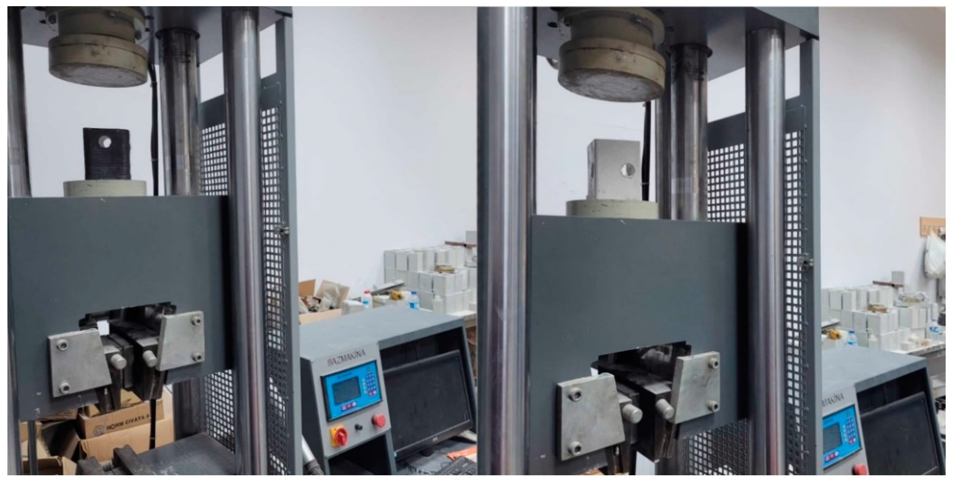
2. Experimental Program
3. Results and Discussion
4. Conclusions
- (1)
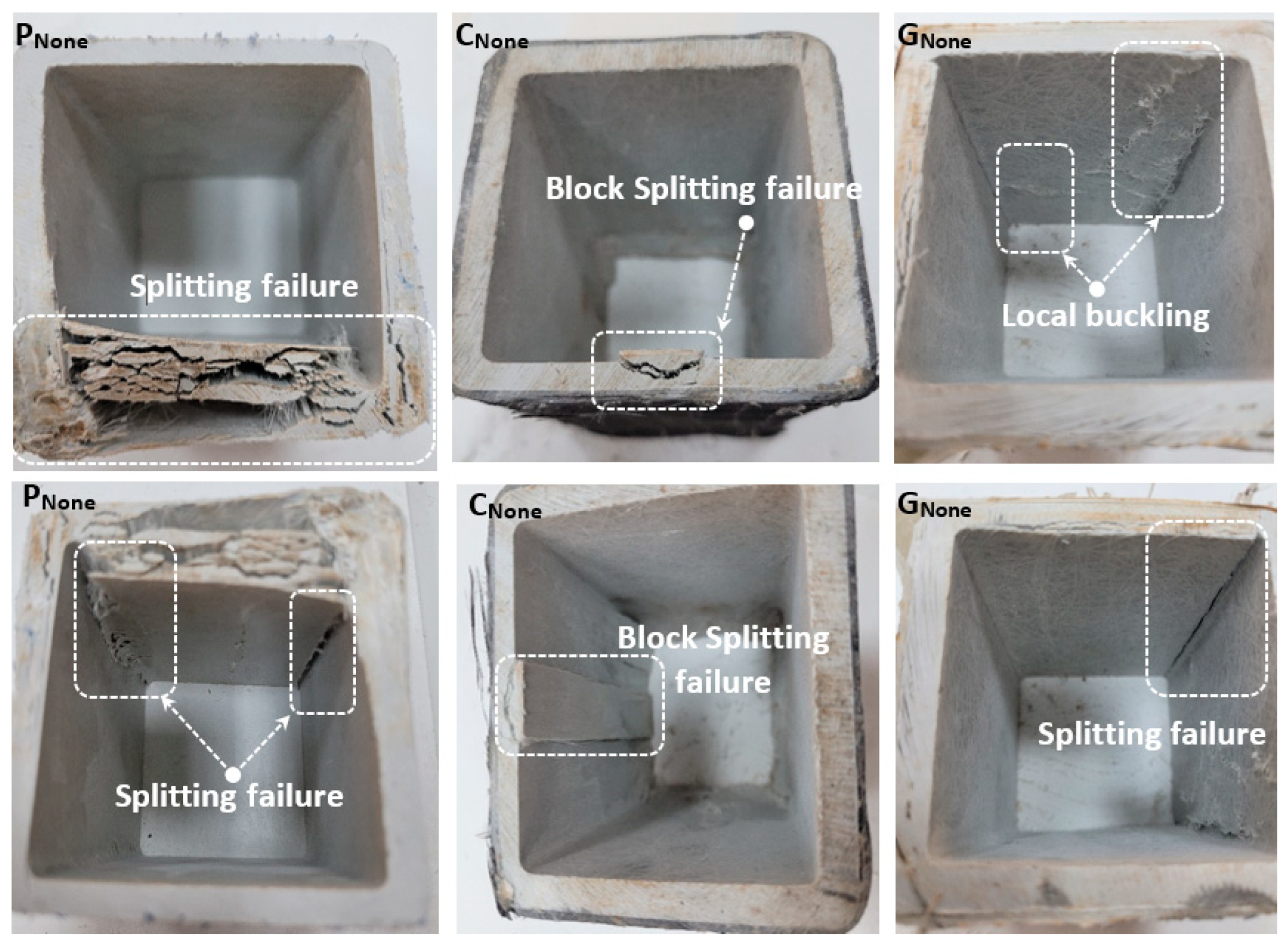
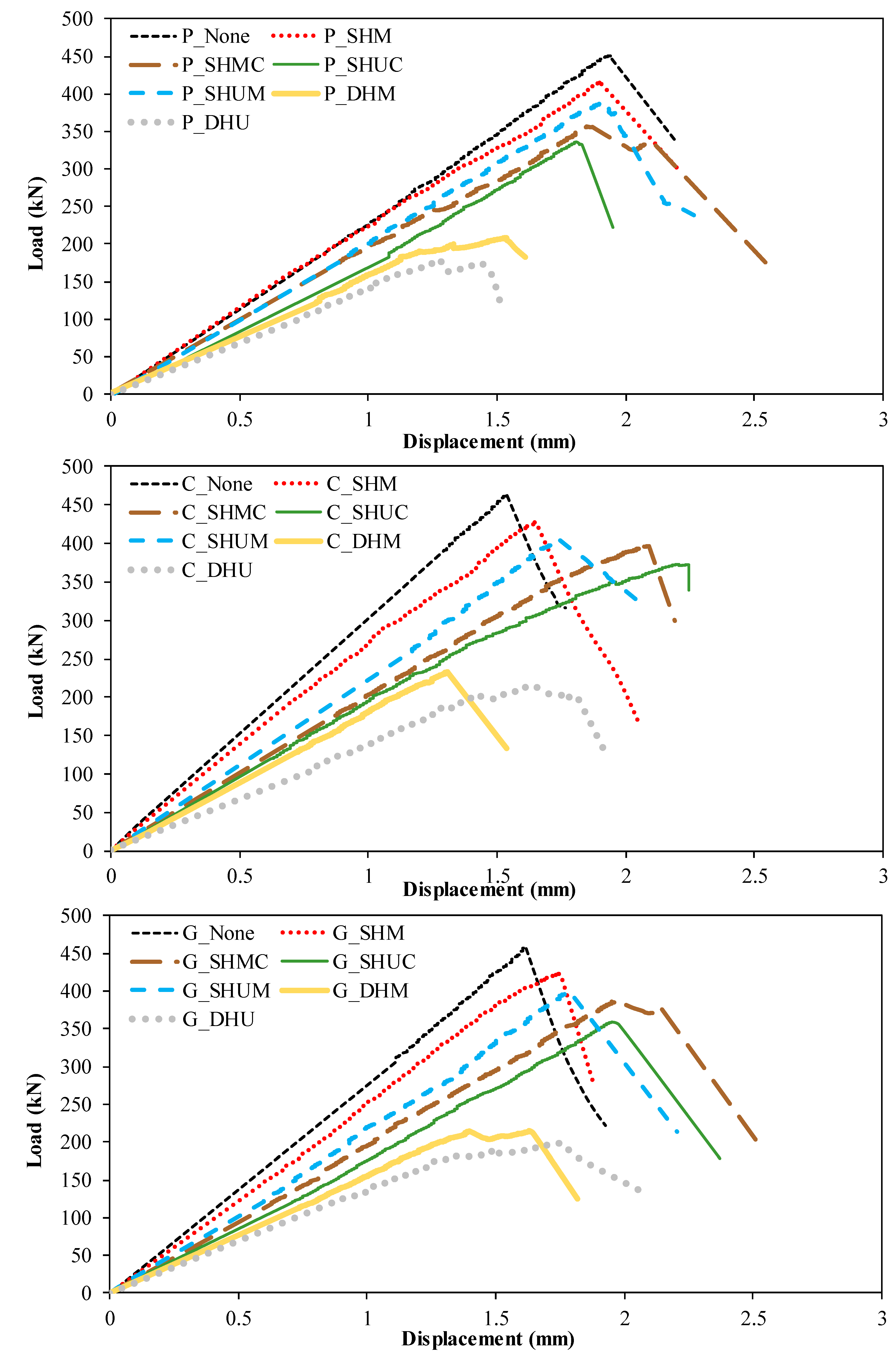
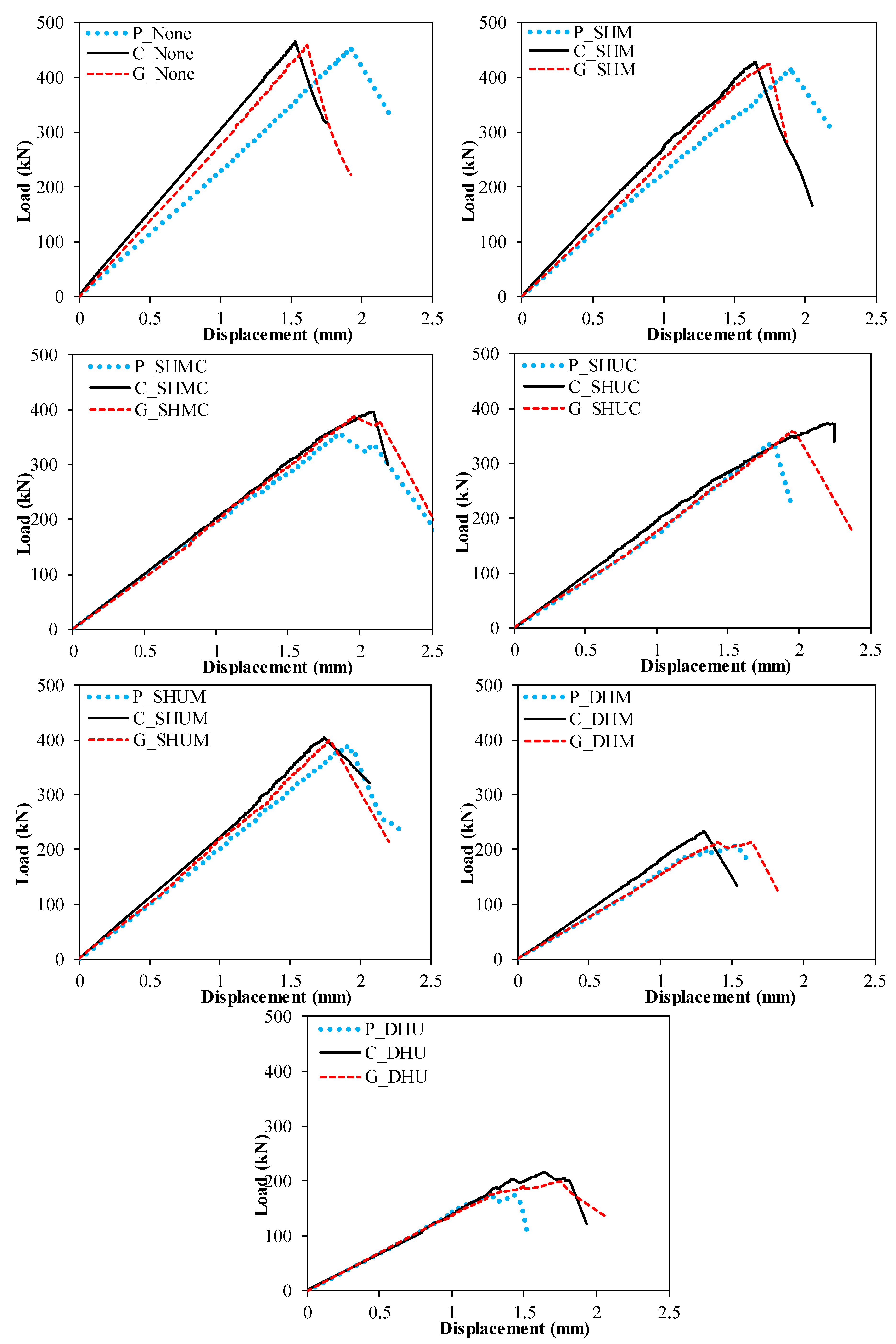
- The PNone specimen has the highest vertical load-carrying capacity among the non-reinforced specimens. The increase in load-carrying capacity compared to other specimens between 8.6% and 150.6% is changing.
- (2)
- The PDHU specimen represented the specimen with the least axial compressive capacity among the non-reinforced specimens. Compared to other specimens, the decrease in capacity varies between 14% and 60.1%.
- (3)
- Among the specimens reinforced with CFRP and GFRP, CNone and GNone have the highest vertical load-carrying capacity. The increase in capacity of CNone and GNone specimens compared to other specimens varies between 8.7–115.1% and 8.4–129.8%. From this, it is understood that the specimens reinforced with CFRP contribute more to the load-carrying capacity than GFRP.
- (4)
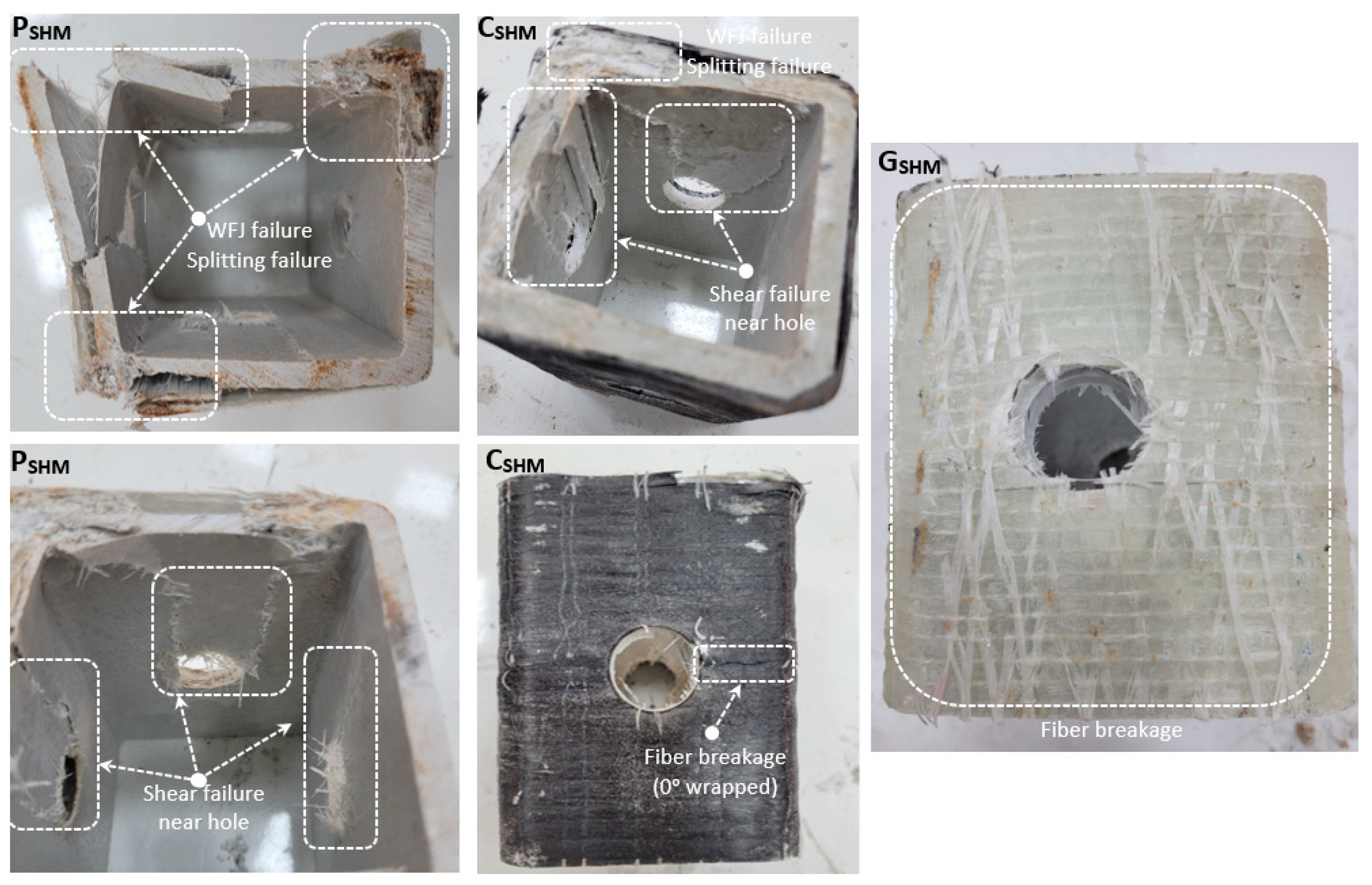
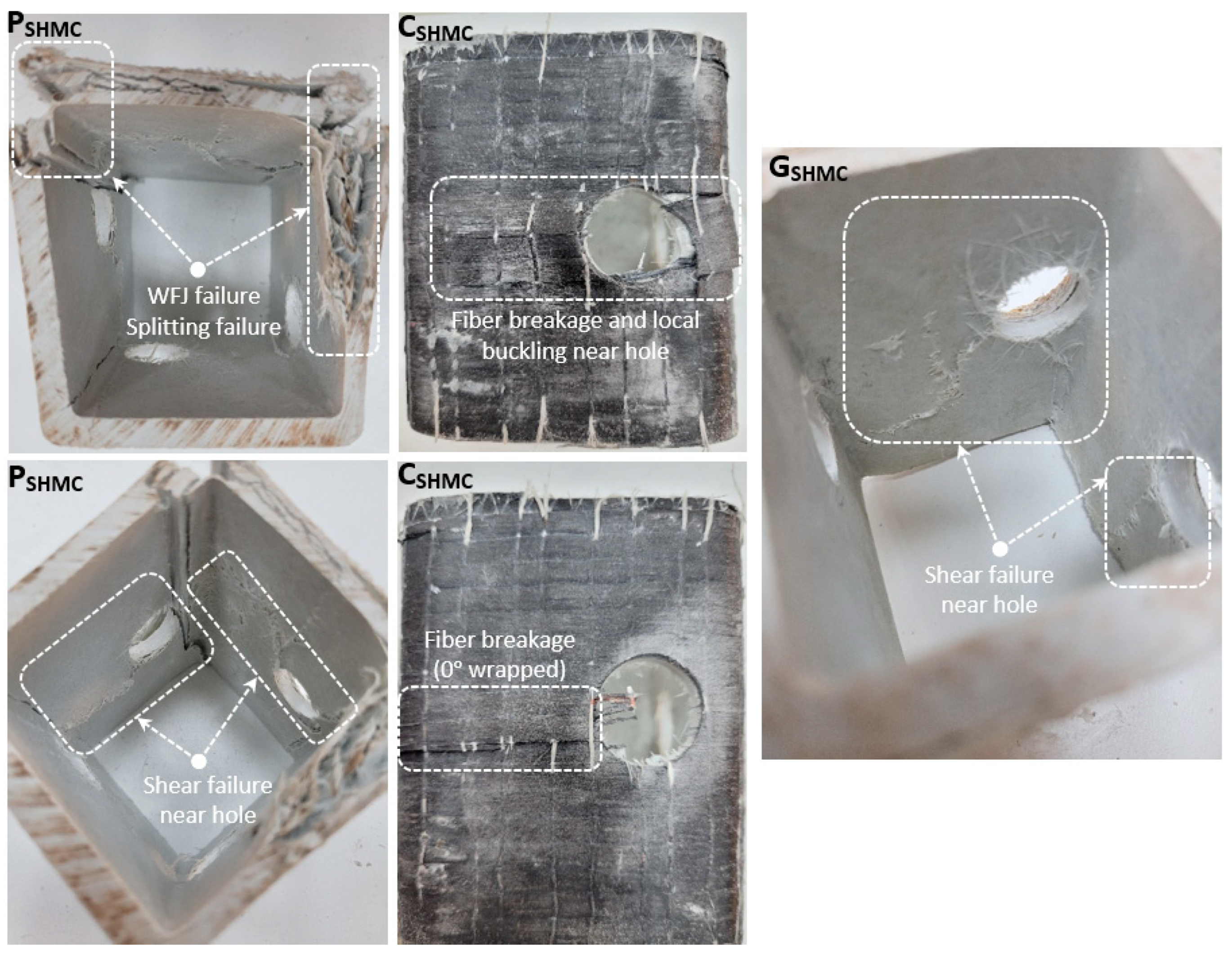
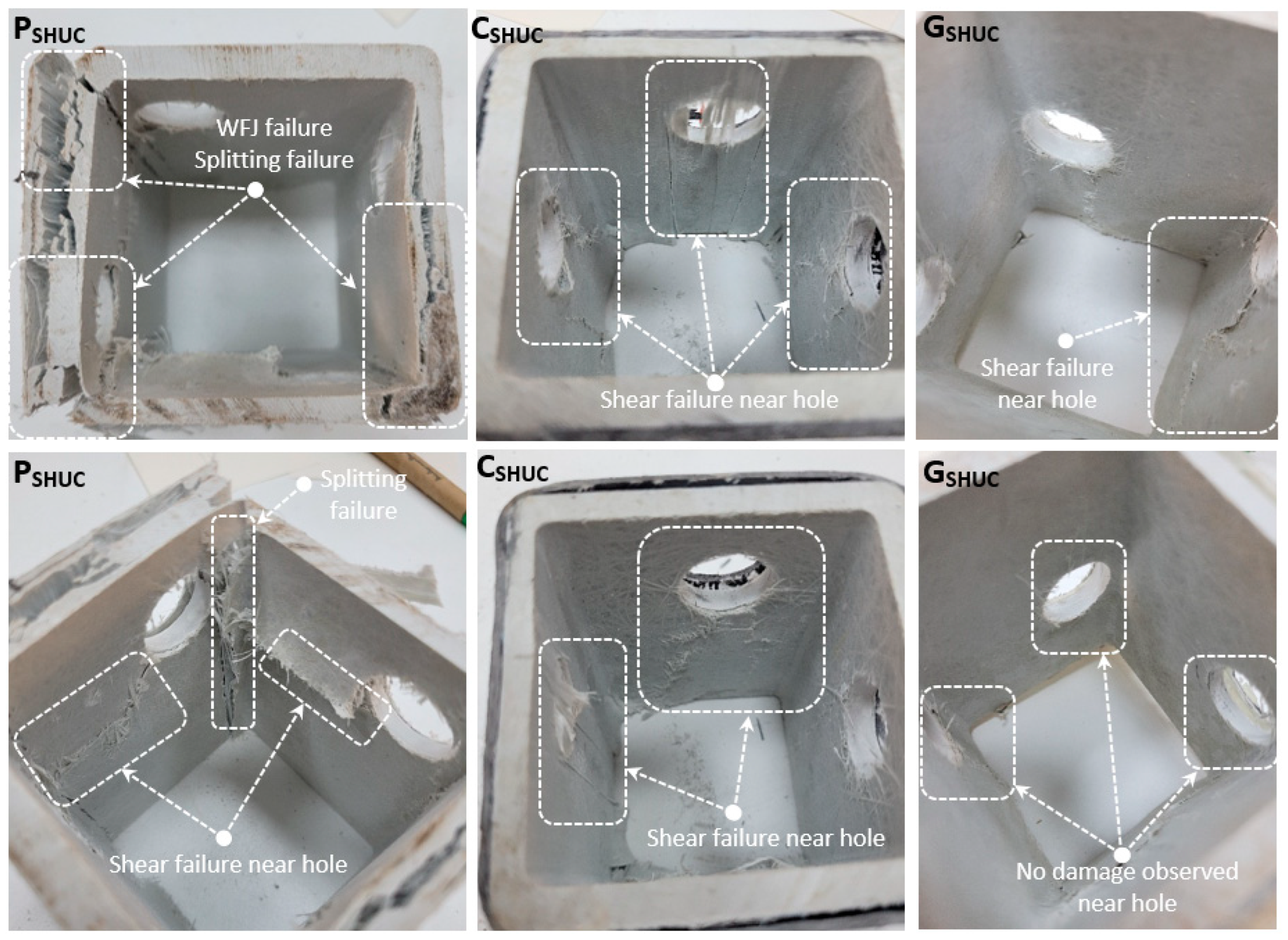
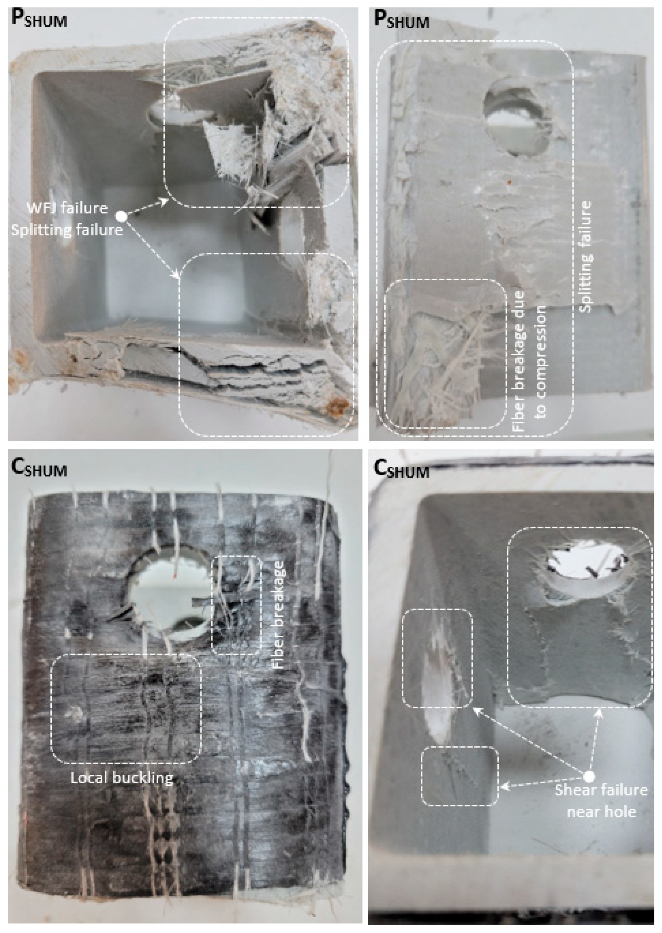
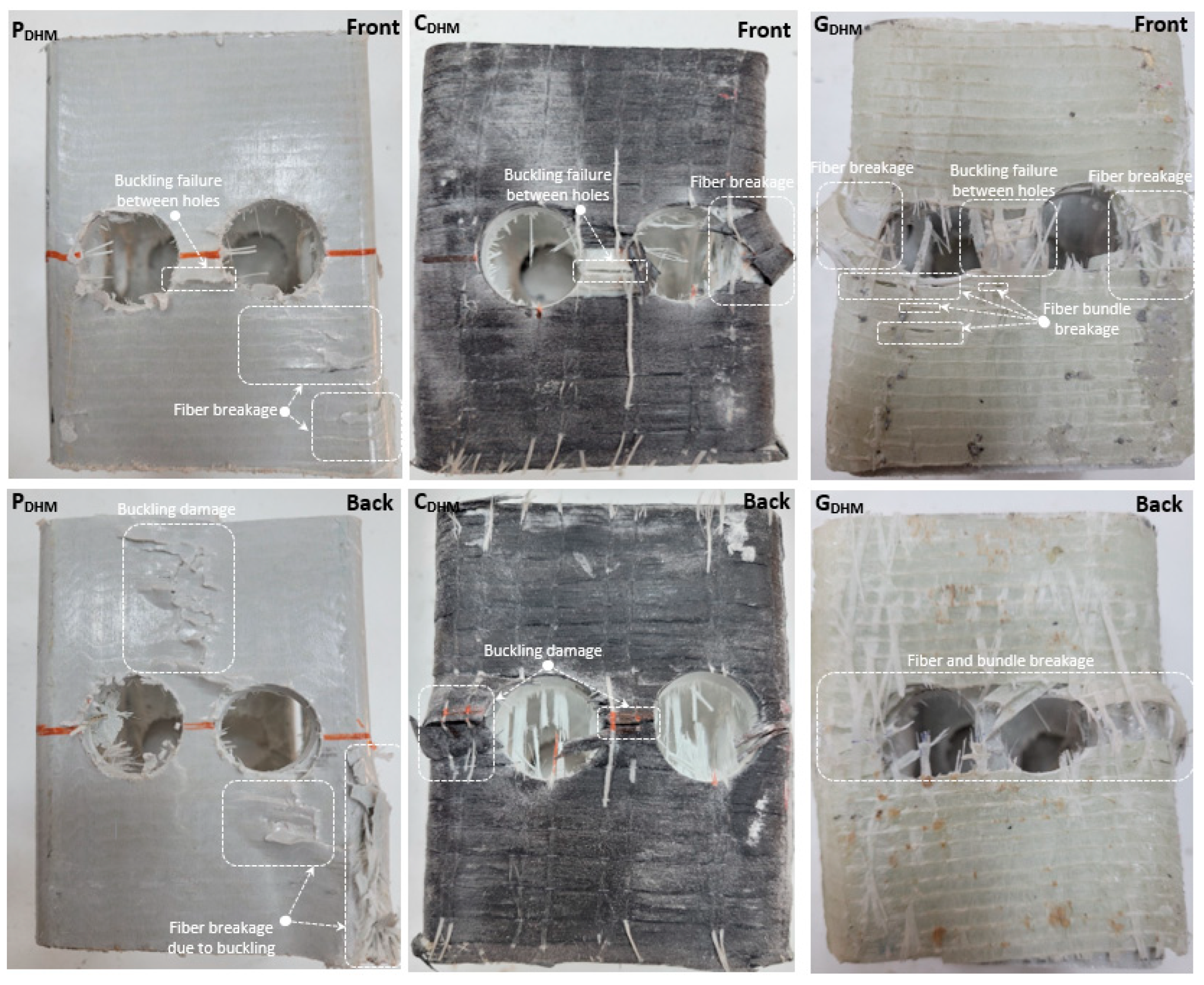
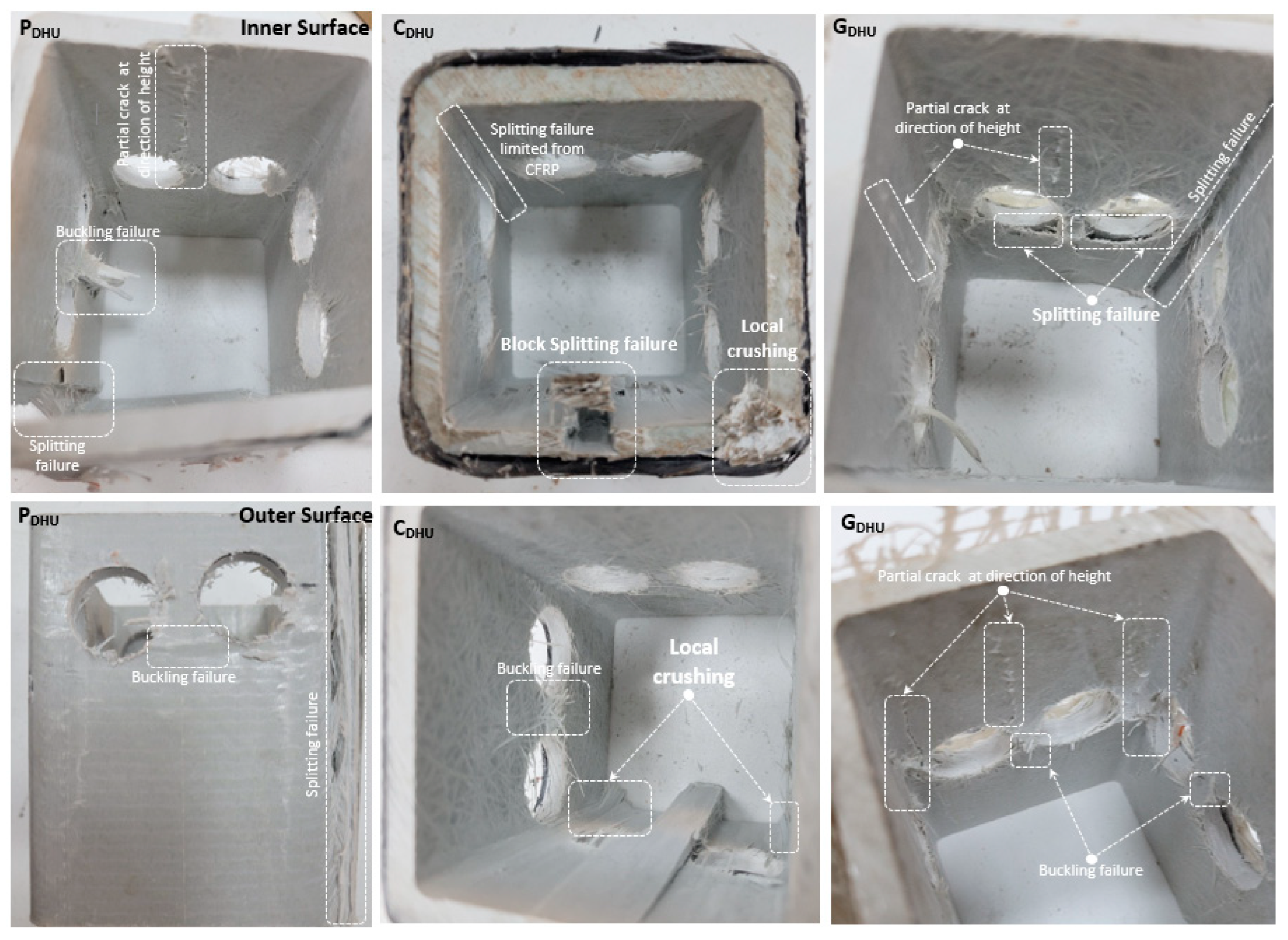
- As a result of the damage analysis, damages occurred in the form of splitting failure, WFJ failure, buckling around the hole, and shear damages in all specimens symbolized with P. While block splitting failure, fiber breakage, and buckling damages were observed in the specimens strengthened with CFRP, fiber bundle breakage, splitting and buckling damages were observed in the specimens strengthened with GFRP.
Author Contributions
Funding
Institutional Review Board Statement
Informed Consent Statement
Data Availability Statement
Acknowledgments
Conflicts of Interest
References
- Vedernikov, A.; Safonov, A.; Tucci, F.; Carlone, P.; Akhatov, I. Pultruded materials and structures: A review. J. Compos. Mater. 2020, 54, 4081–4117. [Google Scholar] [CrossRef]
- Gand, A.K.; Chan, T.-M.; Mottram, J.T. Civil and structural engineering applications, recent trends, research and developments on pultruded fiber reinforced polymer closed sections: A review. Front. Struct. Civ. Eng. 2013, 7, 227–244. [Google Scholar] [CrossRef]
- Vedernikov, A.; Gemi, L.; Madenci, E.; Onuralp Özkılıç, Y.; Yazman, Ş.; Gusev, S.; Sulimov, A.; Bondareva, J.; Evlashin, S.; Konev, S.; et al. Effects of high pulling speeds on mechanical properties and morphology of pultruded GFRP composite flat laminates. Compos. Struct. 2022, 301, 116216. [Google Scholar] [CrossRef]
- Gemi, L.; Madenci, E.; Özkılıç, Y.O.; Yazman, Ş.; Safonov, A. Effect of Fiber Wrapping on Bending Behavior of Reinforced Concrete Filled Pultruded GFRP Composite Hybrid Beams. Polymers 2022, 14, 3740. [Google Scholar] [CrossRef]
- Madencİ, E.; ÖZkiliÇ, Y.O.; Lokman, G. Theoretical investigation on static analysis of pultruded GFRP composite beams. Acad. Platf. J. Eng. Sci. 2020, 8, 483–490. [Google Scholar]
- Correia, J.R.; Bai, Y.; Keller, T. A review of the fire behaviour of pultruded GFRP structural profiles for civil engineering applications. Compos. Struct. 2015, 127, 267–287. [Google Scholar] [CrossRef]
- Keller, T.; Theodorou, N.A.; Vassilopoulos, A.P.; De Castro, J. Effect of natural weathering on durability of pultruded glass fiber–reinforced bridge and building structures. J. Compos. Constr. 2016, 20, 04015025. [Google Scholar] [CrossRef]
- Özkılıç, Y.O.; Madenci, E.; Gemi, L. Tensile and compressive behaviors of the pultruded GFRP lamina. Turk. J. Eng. (TUJE) 2020, 4, 169–175. [Google Scholar]
- Nikbakt, S.; Kamarian, S.; Shakeri, M. A review on optimization of composite structures Part I: Laminated composites. Compos. Struct. 2018, 195, 158–185. [Google Scholar] [CrossRef]
- Almeida-Fernandes, L.; Silvestre, N.; Correia, J.R. Characterization of transverse fracture properties of pultruded GFRP material in tension. Compos. Part B Eng. 2019, 175, 107095. [Google Scholar] [CrossRef]
- Wang, C. Test on pultruded GFRP I-section under web crippling. Compos. Part B Eng. 2015, 77, 27–37. [Google Scholar]
- Correia, J.R.; Branco, F.A.; Ferreira, J. GFRP–concrete hybrid cross-sections for floors of buildings. Eng. Struct. 2009, 31, 1331–1343. [Google Scholar] [CrossRef]
- Nunes, F.; Correia, J.R.; Silvestre, N. Structural behavior of hybrid FRP pultruded beams: Experimental, numerical and analytical studies. Thin-Walled Struct. 2016, 106, 201–217. [Google Scholar] [CrossRef]
- Xin, H.; Mosallam, A.; Liu, Y.; Xiao, Y.; He, J.; Wang, C.; Jiang, Z. Experimental and numerical investigation on in-plane compression and shear performance of a pultruded GFRP composite bridge deck. Compos. Struct. 2017, 180, 914–932. [Google Scholar] [CrossRef]
- Xin, H.; Mosallam, A.S.; Liu, Y.; Wang, C.; He, J. Experimental and numerical investigation on assessing local bearing behavior of a pultruded GFRP bridge deck. Compos. Struct. 2018, 204, 712–730. [Google Scholar] [CrossRef]
- Madenci, E.; Özkılıç, Y.O.; Gemi, L. Experimental and theoretical investigation on flexure performance of pultruded GFRP composite beams with damage analyses. Compos. Struct. 2020, 242, 112162. [Google Scholar] [CrossRef]
- Madenci, E.; Özkılıç, Y.O.; Gemi, L. Buckling and free vibration analyses of pultruded GFRP laminated composites: Experimental, numerical and analytical investigations. Compos. Struct. 2020, 254, 112806. [Google Scholar] [CrossRef]
- Correia, M.M. Structural Behavior of Pultruded GFRP Profiles Experimental Study and Numerical Modeling; Technical University of Lisbon: Lisbon, Portugal, 2012; pp. 1001–1049. [Google Scholar]
- Hai, N.D.; Mutsuyoshi, H.; Asamoto, S.; Matsui, T. Structural behavior of hybrid FRP composite I-beam. Constr. Build. Mater. 2010, 24, 956–969. [Google Scholar] [CrossRef]
- Eskenati, A.R.; Mahboob, A.; Bernat-Maso, E.; Gil, L. Experimental and numerical study of adhesively and bolted connections of pultruded GFRP I-shape profiles. Polymers 2022, 14, 894. [Google Scholar] [CrossRef]
- Vedernikov, A.; Safonov, A.; Tucci, F.; Carlone, P.; Akhatov, I. Modeling spring-in of l-shaped structural profiles pultruded at different pulling speeds. Polymers 2021, 13, 2748. [Google Scholar] [CrossRef]
- Özütok, A.; Madenci, E. Static analysis of laminated composite beams based on higher-order shear deformation theory by using mixed-type finite element method. Int. J. Mech. Sci. 2017, 130, 234–243. [Google Scholar] [CrossRef]
- Özütok, A.; Madenci, E.; Kadioglu, F. Free vibration analysis of angle-ply laminate composite beams by mixed finite element formulation using the Gâteaux differential. Sci. Eng. Compos. Mater. 2014, 21, 257–266. [Google Scholar] [CrossRef]
- Özütok, A.; Madenci, E. Free vibration analysis of cross-ply laminated composite beams by mixed finite element formulation. Int. J. Struct. Stab. Dyn. 2013, 13, 1250056. [Google Scholar] [CrossRef]
- Saghir, F.; Gohari, S.; Moslemi, N.; Abdi, B.; Moloudi, S.; Burvill, C.; Smith, A.; Lucas, S. A semi-empirical approach to evaluate the effect of constituent materials on mechanical strengths of GFRP mortar pipes. Structures 2022, 36, 493–510. [Google Scholar] [CrossRef]
- Tashnizi, E.S.; Gohari, S.; Sharifi, S.; Burvill, C. Optimal winding angle in laminated CFRP composite pipes subjected to patch loading: Analytical study and experimental validation. Int. J. Press. Vessel. Pip. 2020, 180, 104042. [Google Scholar] [CrossRef]
- Gohari, S.; Sharifi, S.; Burvill, C.; Mouloodi, S.; Izadifar, M.; Thissen, P. Localized failure analysis of internally pressurized laminated ellipsoidal woven GFRP composite domes: Analytical, numerical, and experimental studies. Arch. Civ. Mech. Eng. 2019, 19, 1235–1250. [Google Scholar] [CrossRef]
- Alhawamdeh, M.; Alajarmeh, O.; Aravinthan, T.; Shelley, T.; Schubel, P.; Mohammed, A.; Zeng, X. Review on local buckling of hollow box FRP profiles in civil structural applications. Polymers 2021, 13, 4159. [Google Scholar] [CrossRef]
- Nie, X.; Zhang, S.; Gao, Z.; Zeng, Z. A review on the behaviour of reinforced concrete beams with fibre-reinforced polymer-strengthened web openings. Adv. Struct. Eng. 2022, 25, 426–450. [Google Scholar] [CrossRef]
- Osman, B.H.; Wu, E.; Ji, B.; Abdelgader, A.M.S. A state of the art review on reinforced concrete beams with openings retrofitted with FRP. Int. J. Adv. Struct. Eng. 2016, 8, 253–267. [Google Scholar] [CrossRef]
- Soudki, K.; El-Salakawy, E.; Craig, B. Behavior of CFRP strengthened reinforced concrete beams in corrosive environment. J. Compos. Constr. 2007, 11, 291–298. [Google Scholar] [CrossRef]
- Elsanadedy, H.; Al-Salloum, Y.; Al-Zaheri, Z.; Alsayed, S.; Abbas, H. Behavior and design aspects of FRP-strengthened URM walls under out-of-plane loading. J. Compos. Constr. 2016, 20, 04016048. [Google Scholar] [CrossRef]
- Elsanadedy, H.; Abbas, H.; Al-Salloum, Y.; Almusallam, T. Prediction of intermediate crack debonding strain of externally bonded FRP laminates in RC beams and one-way slabs. J. Compos. Constr. 2014, 18, 04014008. [Google Scholar] [CrossRef]
- Qaidi, S.; Al-Kamaki, Y.S.S.; Al-Mahaidi, R.; Mohammed, A.S.; Ahmed, H.U.; Zaid, O.; Althoey, F.; Ahmad, J.; Isleem, H.F.; Bennetts, I. Investigation of the effectiveness of CFRP strengthening of concrete made with recycled waste PET fine plastic aggregate. PLoS ONE 2022, 17, e0269664. [Google Scholar] [CrossRef] [PubMed]
- Özkılıç, Y.O.; Aksoylu, C.; Yazman, Ş.; Gemi, L.; Arslan, M.H. Behavior of CFRP-strengthened RC beams with circular web openings in shear zones: Numerical study. Structures 2022, 41, 1369–1389. [Google Scholar] [CrossRef]
- Gemi, L.; Alsdudi, M.; Aksoylu, C.; Yazman, S.; Ozkilic, Y.O.; Arslan, M.H. Optimum amount of CFRP for strengthening shear deficient reinforced concrete beams. Steel Compos. Struct. 2022, 43, 735–757. [Google Scholar]
- Arslan, M.H.; Yazman, Ş.; Hamad, A.A.; Aksoylu, C.; Özkılıç, Y.O.; Gemi, L. Shear strengthening of reinforced concrete T-beams with anchored and non-anchored CFRP fabrics. Structures 2022, 39, 527–542. [Google Scholar] [CrossRef]
- Özkılıç, Y.O.; Yazman, Ş.; Aksoylu, C.; Arslan, M.H.; Gemi, L. Numerical investigation of the parameters influencing the behavior of dapped end prefabricated concrete purlins with and without CFRP strengthening. Constr. Build. Mater. 2021, 275, 122173. [Google Scholar] [CrossRef]
- Aksoylu, C.; Özkılıç, Y.O.; Yazman, Ş.; Gemi, L.; Arslan, M.H. Experimental and Numerical Investigation of Load Bearing Capacity of Thinned End Precast Purlin Beams and Solution Proposals. Teknik Dergi 2021, 614, 10823–10858. [Google Scholar]
- Aksoylu, C.; Yazman, Ş.; Özkılıç, Y.O.; Gemi, L.; Arslan, M.H. Experimental analysis of reinforced concrete shear deficient beams with circular web openings strengthened by CFRP composite. Compos. Struct. 2020, 249, 112561. [Google Scholar] [CrossRef]
- Gemi, L.; Aksoylu, C.; Yazman, Ş.; Özkılıç, Y.O.; Arslan, M.H. Experimental investigation of shear capacity and damage analysis of thinned end prefabricated concrete purlins strengthened by CFRP composite. Compos. Struct. 2019, 229, 111399. [Google Scholar] [CrossRef]
- Mansour, W. Numerical analysis of the shear behavior of FRP-strengthened continuous RC beams having web openings. Eng. Struct. 2021, 227, 111451. [Google Scholar] [CrossRef]
- Aksoylu, C.; Özkılıç, Y.O.; Arslan, M.H. Mechanical Steel Stitches: An Innovative Approach for Strengthening Shear Deficiency in Undamaged Reinforced Concrete Beams. Buildings 2022, 12, 1501. [Google Scholar] [CrossRef]
- Al-Shalif, S.A.; Akın, A.; Aksoylu, C.; Arslan, M.H. Strengthening of shear-critical reinforced concrete T-beams with anchored and non-anchored GFRP fabrics applications. Structures 2022, 44, 809–827. [Google Scholar] [CrossRef]
- Aksoylu, C. Experimental analysis of shear deficient reinforced concrete beams strengthened by glass fiber strip composites and mechanical stitches. Steel Compos. Struct. Int. J. 2021, 40, 267–285. [Google Scholar]
- Fatehi Makki, R.; Talib Jassem, A.; Abd Al-Latef Jassem, H. Behavior of reactive-powder concrete deep beams with CFRP-strengthened openings. Pract. Period. Struct. Des. Constr. 2019, 24, 04019016. [Google Scholar] [CrossRef]
- Arabzadeh, A.; Karimizadeh, H. Experimental study of RC deep beams with opening and FRP composites installed by means of EBR and EBROG methods. Constr. Build. Mater. 2019, 208, 780–791. [Google Scholar] [CrossRef]
- Allawi, A.A.; Oukaili, N.K.; Jasim, W.A. Strength compensation of deep beams with large web openings using carbon fiber–reinforced polymer sheets. Adv. Struct. Eng. 2021, 24, 165–182. [Google Scholar] [CrossRef]
- Rahim, N.I.; Mohammed, B.S.; Al-Fakih, A.; Wahab, M.; Liew, M.; Anwar, A.; Amran, Y. Strengthening the structural behavior of web openings in RC deep beam using CFRP. Materials 2020, 13, 2804. [Google Scholar] [CrossRef]
- Almusallam, T.; Al-Salloum, Y.; Elsanadedy, H.; Alshenawy, A.; Iqbal, R. Behavior of FRP-strengthened RC beams with large rectangular web openings in flexure zones: Experimental and numerical study. Int. J. Concr. Struct. Mater. 2018, 12, 47. [Google Scholar] [CrossRef]
- Elsanadedy, H.M.; Al-Salloum, Y.A.; Almusallam, T.H.; Alshenawy, A.O.; Abbas, H. Experimental and numerical study on FRP-upgraded RC beams with large rectangular web openings in shear zones. Constr. Build. Mater. 2019, 194, 322–343. [Google Scholar] [CrossRef]
- Hemzah, S.A.; Alyhya, W.S.; Hassan, S.A. Experimental investigation for structural behaviour of self-compacting reinforced concrete hollow beams with in-place circular openings strengthened with CFRP laminates. Structures 2020, 24, 99–106. [Google Scholar] [CrossRef]
- Mansur, M.; Tan, K.-H.; Wei, W. Effects of creating an opening in existing beams. Struct. J. 1999, 96, 899–905. [Google Scholar]
- Teng, J.G.; Zhang, S.S.; Dai, J.; Chen, J. Three-dimensional meso-scale finite element modeling of bonded joints between a near-surface mounted FRP strip and concrete. Comput. Struct. 2013, 117, 105–117. [Google Scholar] [CrossRef]
- Aksoylu, C.; Özkılıç, Y.O.; Madenci, E.; Safonov, A. Compressive behavior of pultruded GFRP boxes with concentric openings strengthened by different composite wrappings. Polymers 2022, 14, 4095. [Google Scholar] [CrossRef]


| Property | Mean Value (MPa) |
|---|---|
| Longitudinal tensile modulus of elasticity | 23,000 |
| Transverse tensile modulus of elasticity | 7000 |
| Longitudinal tensile strength | 240 |
| Transverse tensile strength | 50 |
| Longitudinal compressive strength | 150 |
| Transverse compressive strength | 70 |
| Shear strength | 25 |
| CFRP Strip Properties (800 gr/m2) | Values |
|---|---|
| Thickness (mm) | 0.85 |
| Tensile strength (GPa) | 4.4 |
| Modulus of elasticity (GPa) | 235 |
| Rupture strain (%) | 1.87 |
| GFRP strip properties (1200 gr/m2) | Values |
| Thickness (mm) | 1.2 |
| Tensile strength (GPa) | 3.5 |
| Modulus of elasticity (GPa) | 80 |
| Rupture strain (%) | 4.37 |
| Epoxy+Hardener (F-1564+F-3486) | Values |
| Tensile strength (GPa) | 0.055 |
| Modulus of elasticity (GPa) | 2.090 |
| Rupture strain (%) | 4.06 ± 1.27 |
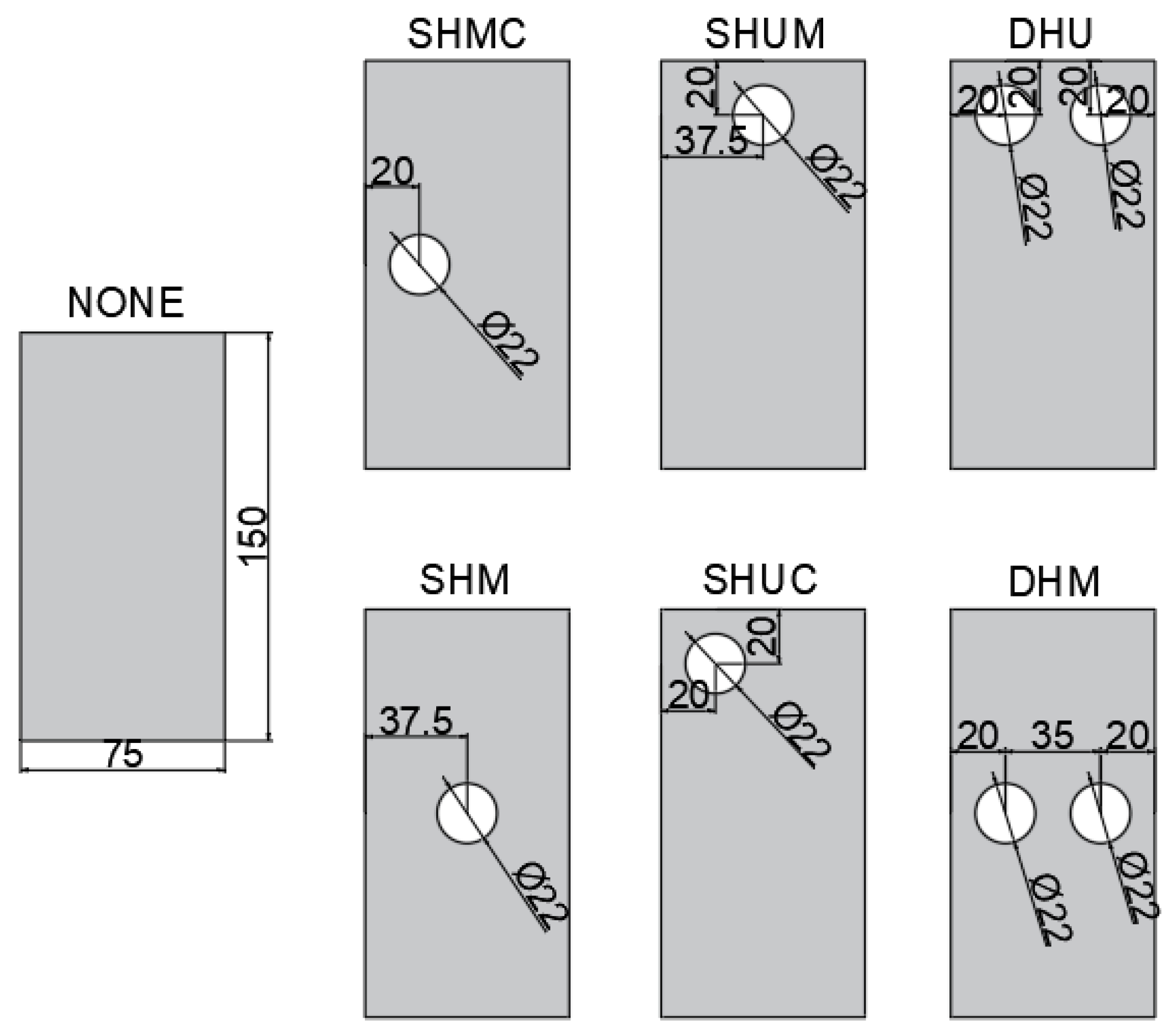
| Specimen | Hole Size | P (kN) | Decline Ratio % | C (kN) | Decline Ratio % | G (kN) | Decline Ratio % |
|---|---|---|---|---|---|---|---|
| None | - | 450.6 | 1 | 464.9 | 1 | 458.6 | 1 |
| SHM | 22 | 414.9 | 7.9 | 427.5 | 8.0 | 422.8 | 7.8 |
| SHMC | 22 | 356.9 | 20.7 | 396.2 | 14.7 | 387.4 | 15.5 |
| SHUC | 22 | 335.6 | 25.5 | 372.4 | 19.8 | 359.8 | 21.5 |
| SHUM | 22 | 389.8 | 13.4 | 406.4 | 12.5 | 399.8 | 12.8 |
| DHM | 22 | 209.1 | 53.5 | 234.2 | 49.6 | 215.6 | 52.9 |
| DHU | 22 | 179.8 | 60.1 | 216.1 | 53.5 | 199.5 | 56.5 |
Publisher’s Note: MDPI stays neutral with regard to jurisdictional claims in published maps and institutional affiliations. |
© 2022 by the authors. Licensee MDPI, Basel, Switzerland. This article is an open access article distributed under the terms and conditions of the Creative Commons Attribution (CC BY) license (https://creativecommons.org/licenses/by/4.0/).
Share and Cite
Madenci, E.; Özkılıç, Y.O.; Aksoylu, C.; Safonov, A. The Effects of Eccentric Web Openings on the Compressive Performance of Pultruded GFRP Boxes Wrapped with GFRP and CFRP Sheets. Polymers 2022, 14, 4567. https://doi.org/10.3390/polym14214567
Madenci E, Özkılıç YO, Aksoylu C, Safonov A. The Effects of Eccentric Web Openings on the Compressive Performance of Pultruded GFRP Boxes Wrapped with GFRP and CFRP Sheets. Polymers. 2022; 14(21):4567. https://doi.org/10.3390/polym14214567
Chicago/Turabian StyleMadenci, Emrah, Yasin Onuralp Özkılıç, Ceyhun Aksoylu, and Alexander Safonov. 2022. "The Effects of Eccentric Web Openings on the Compressive Performance of Pultruded GFRP Boxes Wrapped with GFRP and CFRP Sheets" Polymers 14, no. 21: 4567. https://doi.org/10.3390/polym14214567
APA StyleMadenci, E., Özkılıç, Y. O., Aksoylu, C., & Safonov, A. (2022). The Effects of Eccentric Web Openings on the Compressive Performance of Pultruded GFRP Boxes Wrapped with GFRP and CFRP Sheets. Polymers, 14(21), 4567. https://doi.org/10.3390/polym14214567