
Validation of HepG2/C3A Cell Cultures in Cyclic Olefin Copolymer Based Microfluidic Bioreactors

 , , , , and
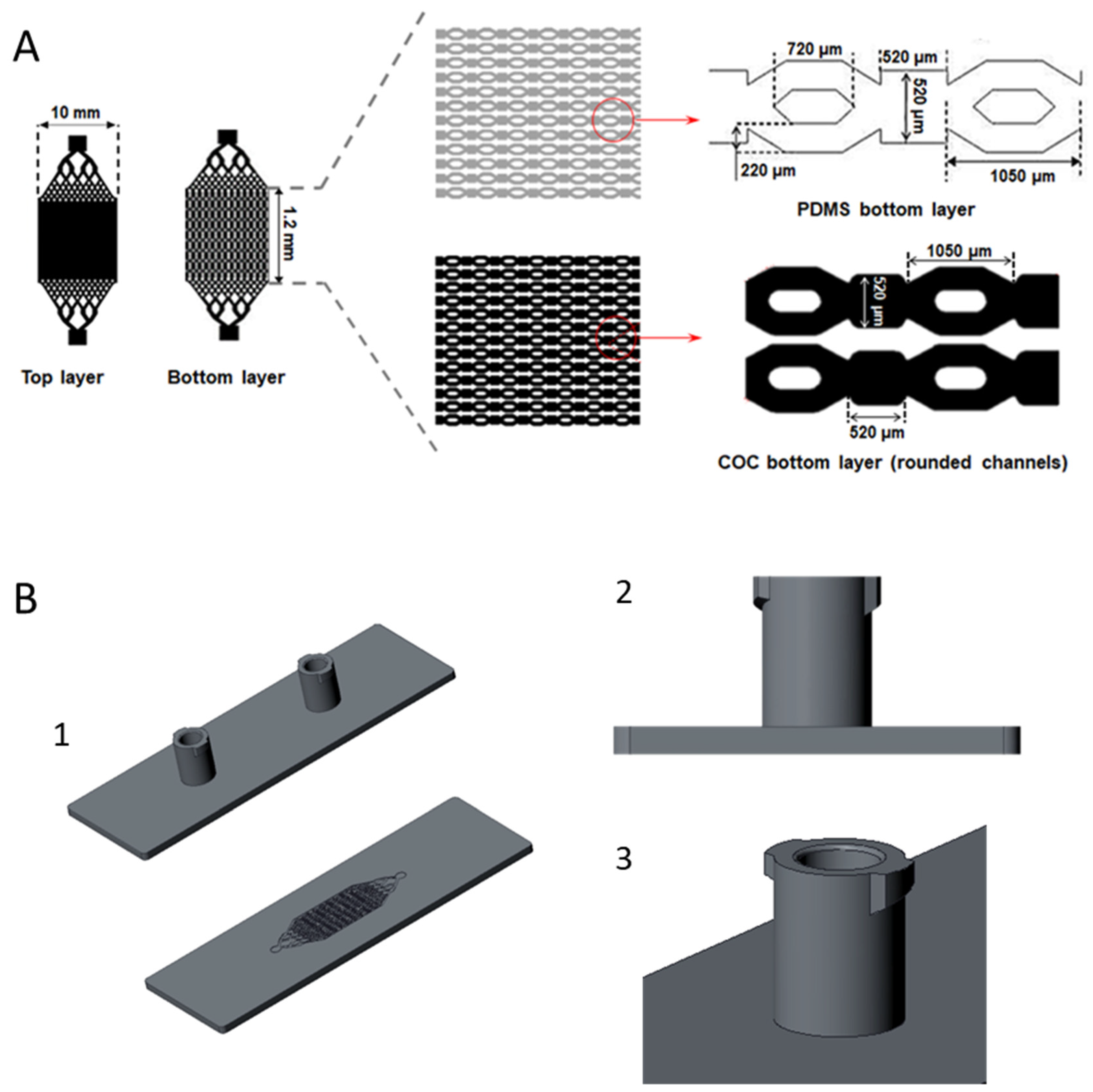
Abstract
1. Introduction
2. Materials and Methods
2.1. Materials
2.2. Design and Manufacturing of the Bioreactor
2.3. Scanning Electron Microscopy
2.4. Flow and Pressure Measurements
2.5. Cells
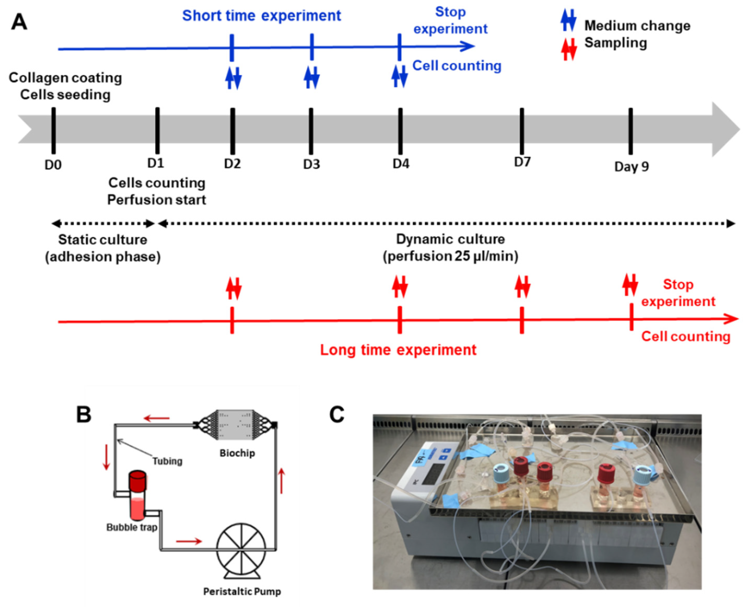
2.6. Dynamic Culture in Biochip
2.7. Cell Counting and Viability
2.8. Albumin Measurements
2.9. Immunostaining and Confocal Microscopy
3. Results
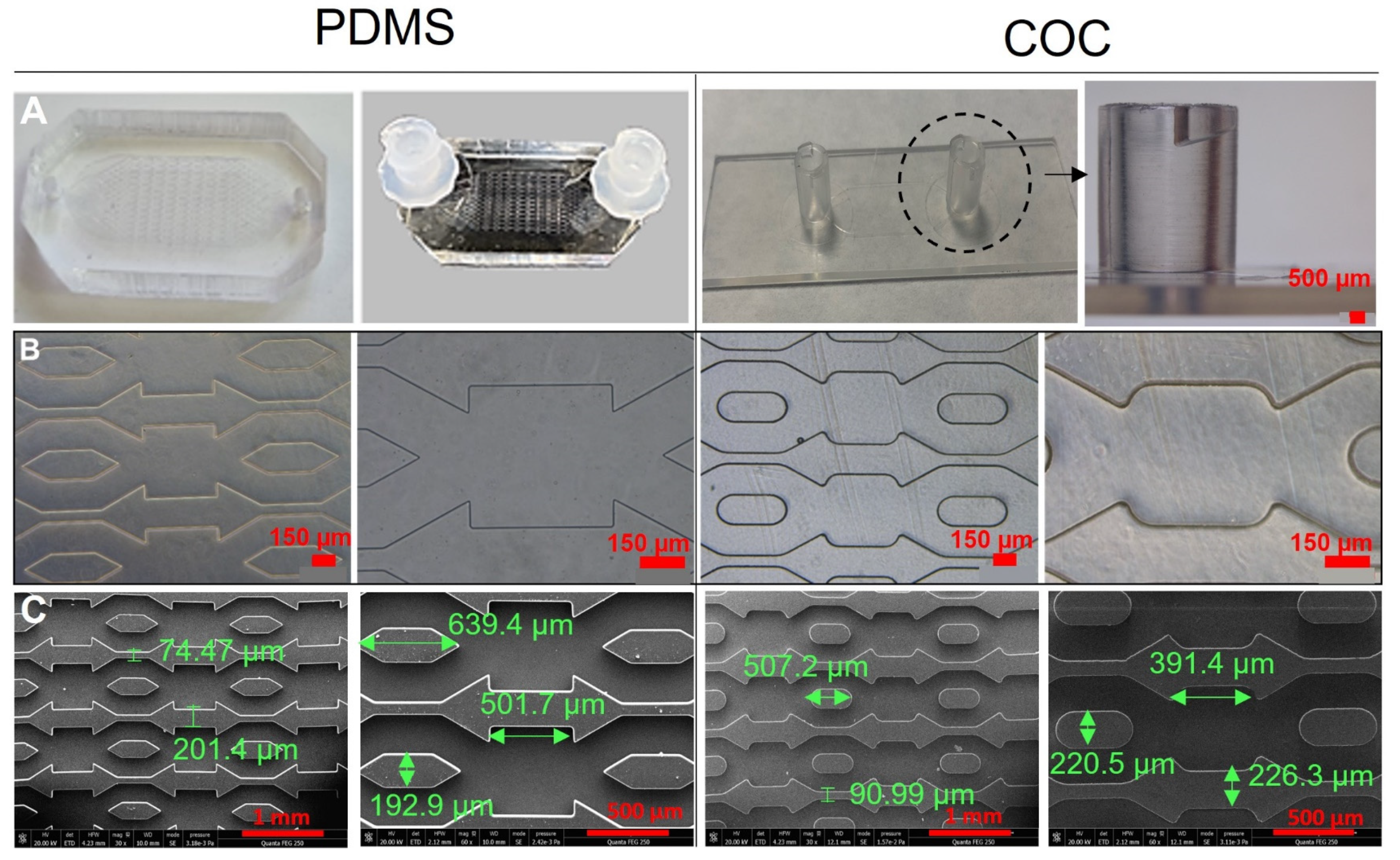
3.1. Biochips Characterization
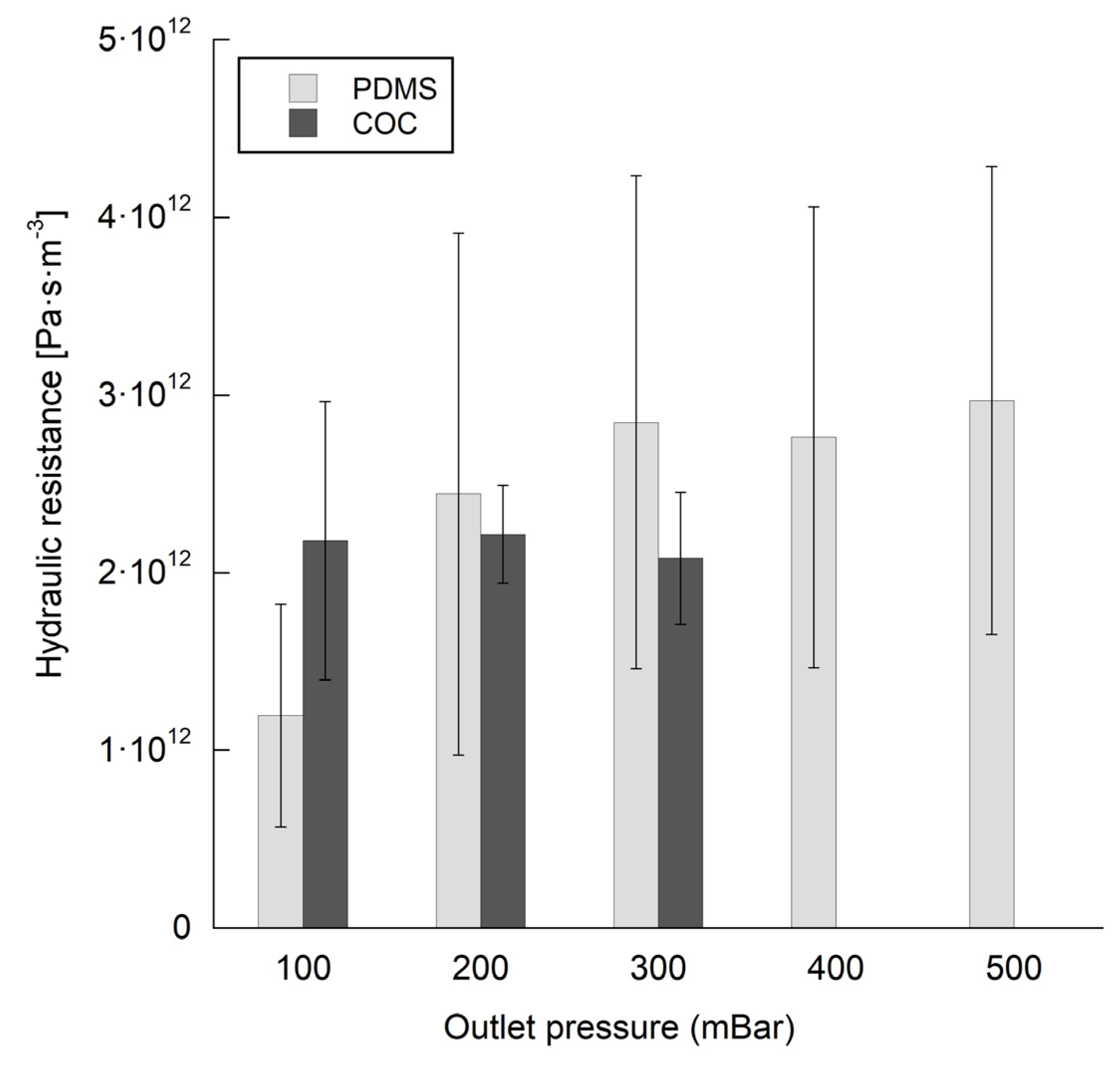
3.2. Flow and Pressure Measurements
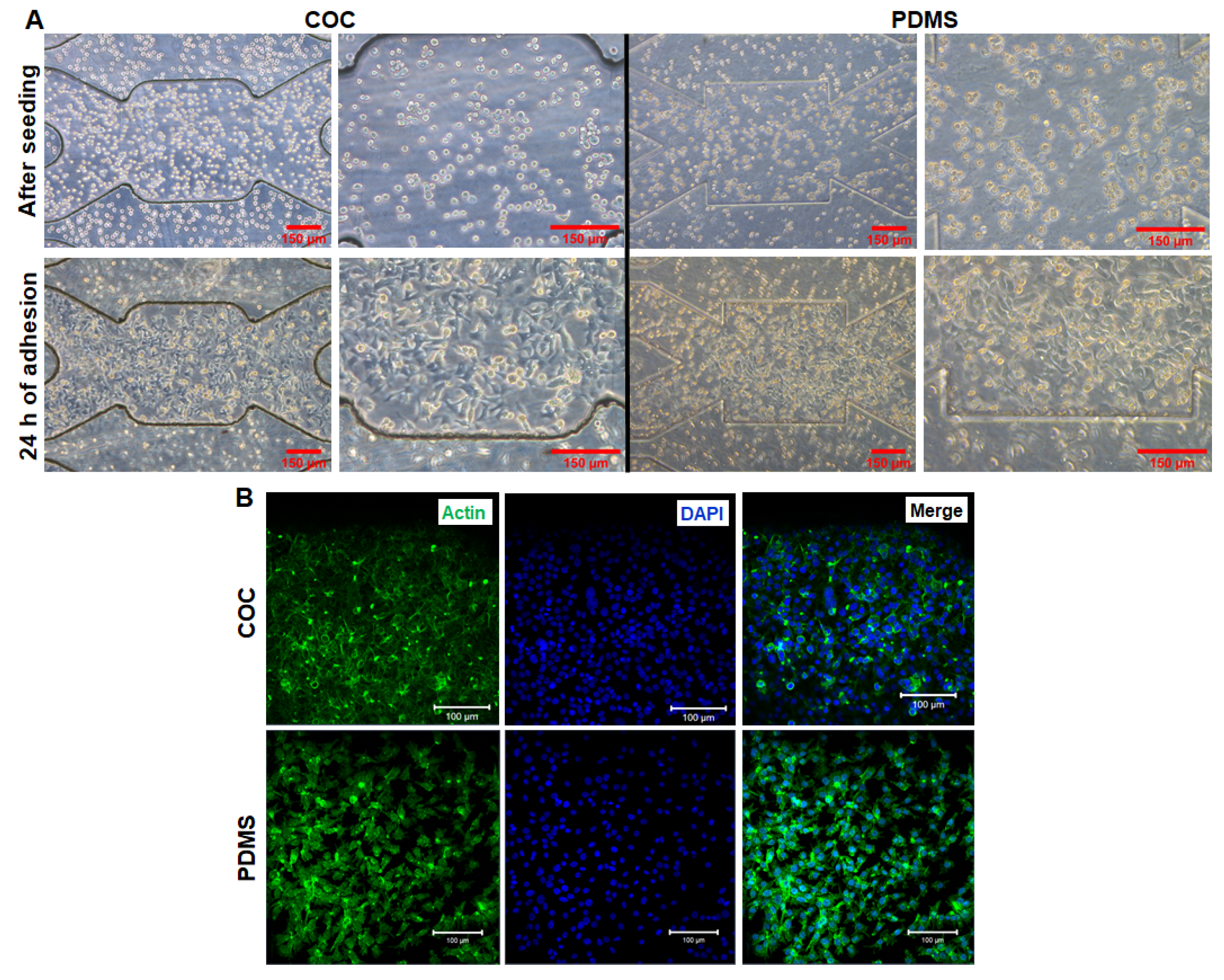
3.3. HepG2/C3a Cell Adhesion on COC and PDMS Biochips
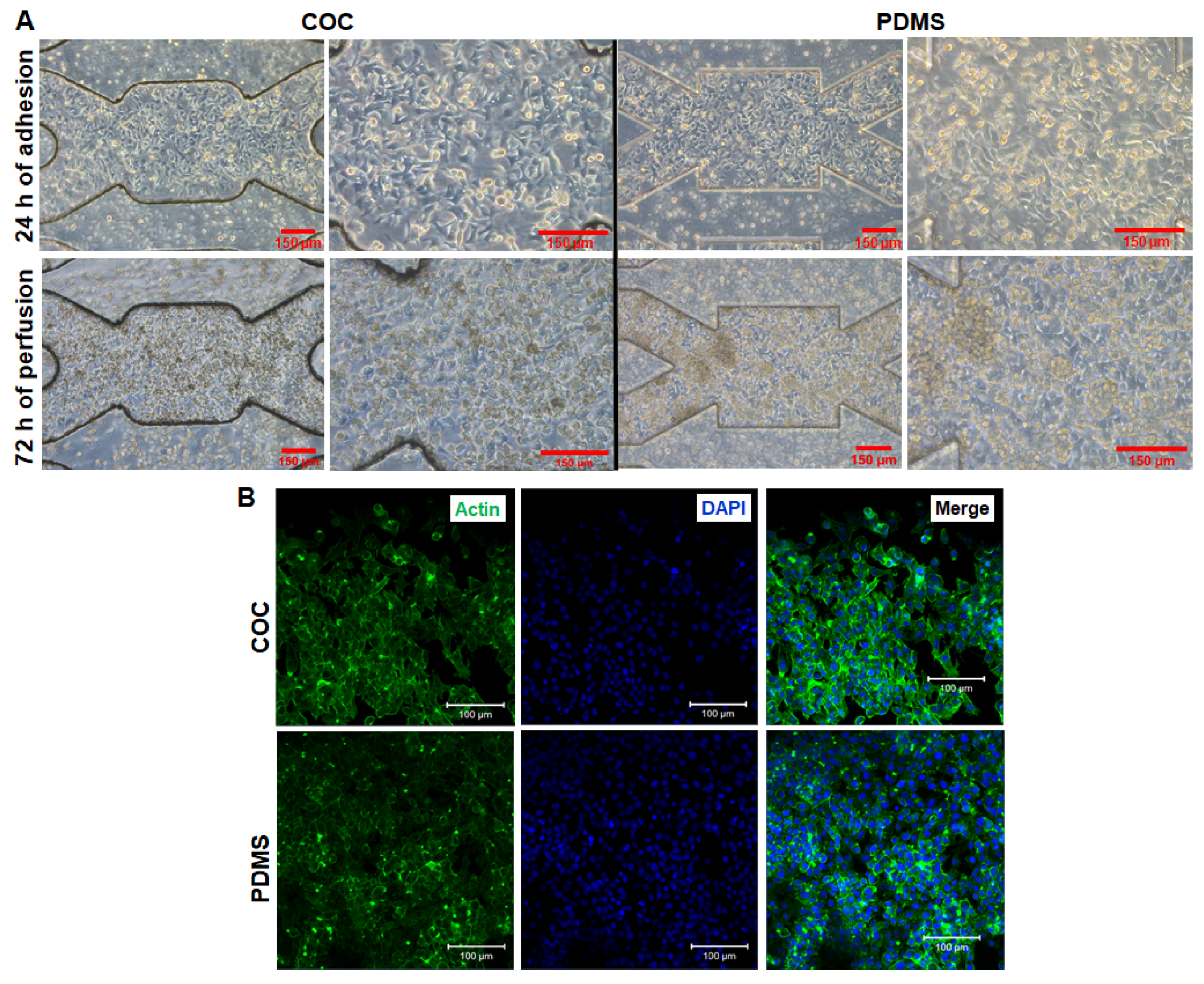
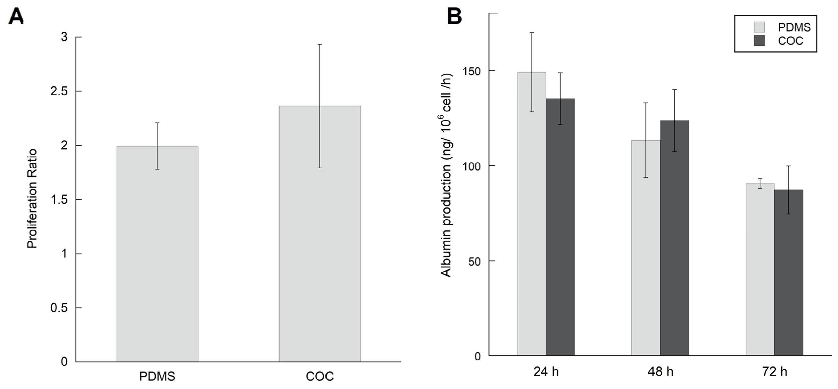
3.4. Short Time Dynamic Culture of HepG2/C3a in Biochips
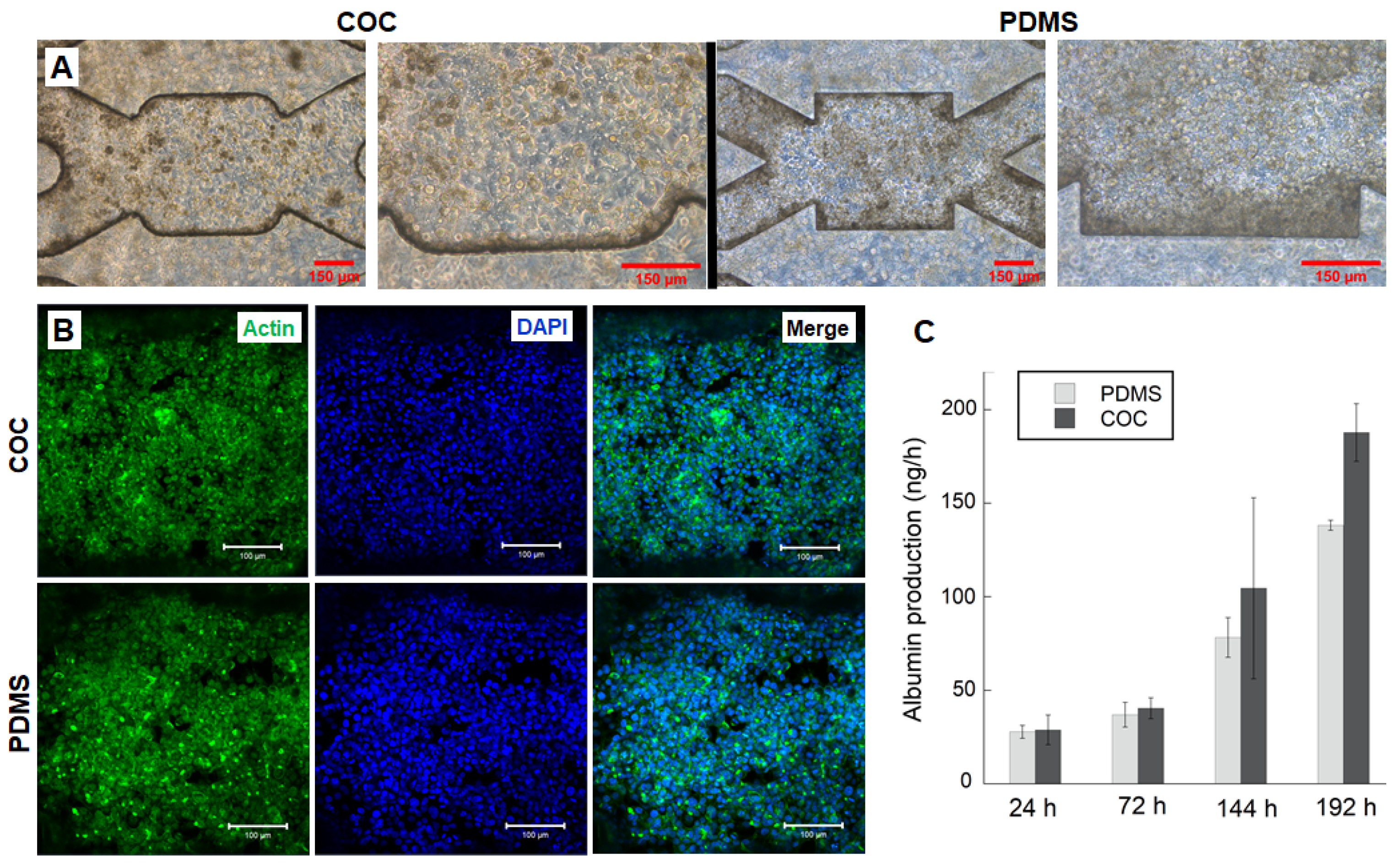
3.5. HepG2/C3a Cells Behaviour in Long Time Experiment
4. Discussion
5. Conclusions
Supplementary Materials
Author Contributions
Funding
Institutional Review Board Statement
Informed Consent Statement
Data Availability Statement
Acknowledgments
Conflicts of Interest
References
- Terjung, R. (Ed.) Comprehensive Physiology, 1st ed.; Wiley: Hoboken, NJ, USA, 2011; ISBN 978-0-470-65071-4. [Google Scholar]
- Messelmani, T.; Morisseau, L.; Sakai, Y.; Legallais, C.; Goff, A.L.; Leclerc, E.; Jellali, R. Liver Organ-on-Chip Models for Toxicity Studies and Risk Assessment. Lab Chip 2022, 22, 2423–2450. [Google Scholar] [CrossRef] [PubMed]
- Soldatow, V.Y.; LeCluyse, E.L.; Griffith, L.G.; Rusyn, I. In Vitro Models for Liver Toxicity Testing. Toxicol. Res. 2013, 2, 23–39. [Google Scholar] [CrossRef]
- Gebhardt, R.; Hengstler, J.G.; Müller, D.; Glöckner, R.; Buenning, P.; Laube, B.; Schmelzer, E.; Ullrich, M.; Utesch, D.; Nicola, H.; et al. New Hepatocyte In Vitro Systems for Drug Metabolism: Metabolic Capacity and Recommendations for Application in Basic Research and Drug Development, Standard Operation Procedures. Drug Metab. Rev. 2003, 35, 145–213. [Google Scholar] [CrossRef] [PubMed]
- Guillouzo, A. Liver Cell Models in in Vitro Toxicology. Environ. Health Perspect. 1998, 106, 22. [Google Scholar]
- Merlier, F.; Jellali, R.; Leclerc, E. Online Monitoring of Hepatic Rat Metabolism by Coupling a Liver Biochip and a Mass Spectrometer. Analyst 2017, 142, 3747–3757. [Google Scholar] [CrossRef] [PubMed]
- Viravaidya, K.; Sin, A.; Shuler, M.L. Development of a Microscale Cell Culture Analog To Probe Naphthalene Toxicity. Biotechnol. Prog. 2008, 20, 316–323. [Google Scholar] [CrossRef]
- Chen, X.; Zhang, Y.S.; Zhang, X.; Liu, C. Organ-on-a-Chip Platforms for Accelerating the Evaluation of Nanomedicine. Bioact. Mater. 2021, 6, 1012–1027. [Google Scholar] [CrossRef]
- An, F.; Qu, Y.; Liu, X.; Zhong, R.; Luo, Y. Organ-on-a-Chip: New Platform for Biological Analysis. Anal. Chem. Insights 2015, 10, ACI.S28905. [Google Scholar] [CrossRef]
- Kimura, H.; Sakai, Y.; Fujii, T. Organ/Body-on-a-Chip Based on Microfluidic Technology for Drug Discovery. Drug Metab. Pharmacokinet. 2018, 33, 43–48. [Google Scholar] [CrossRef]
- Sosa-Hernández, J.E.; Villalba-Rodríguez, A.M.; Romero-Castillo, K.D.; Aguilar-Aguila-Isaías, M.A.; García-Reyes, I.E.; Hernández-Antonio, A.; Ahmed, I.; Sharma, A.; Parra-Saldívar, R.; Iqbal, H.M.N. Organs-on-a-Chip Module: A Review from the Development and Applications Perspective. Micromachines 2018, 9, 536. [Google Scholar] [CrossRef]
- Wu, Q.; Liu, J.; Wang, X.; Feng, L.; Wu, J.; Zhu, X.; Wen, W.; Gong, X. Organ-on-a-Chip: Recent Breakthroughs and Future Prospects. BioMed. Eng. OnLine 2020, 19, 9. [Google Scholar] [CrossRef] [PubMed]
- Bhatia, S.N.; Ingber, D.E. Microfluidic Organs-on-Chips. Nat. Biotechnol. 2014, 32, 760–772. [Google Scholar] [CrossRef] [PubMed]
- Hassan, S.; Sebastian, S.; Maharjan, S.; Lesha, A.; Carpenter, A.; Liu, X.; Xie, X.; Livermore, C.; Zhang, Y.S.; Zarrinpar, A. Liver-on-a-Chip Models of Fatty Liver Disease. Hepatology 2020, 71, 733–740. [Google Scholar] [CrossRef]
- Bhise, N.S.; Manoharan, V.; Massa, S.; Tamayol, A.; Ghaderi, M.; Miscuglio, M.; Lang, Q.; Shrike Zhang, Y.; Shin, S.R.; Calzone, G.; et al. A Liver-on-a-Chip Platform with Bioprinted Hepatic Spheroids. Biofabrication 2016, 8, 014101. [Google Scholar] [CrossRef] [PubMed]
- Essaouiba, A.; Okitsu, T.; Kinoshita, R.; Jellali, R.; Shinohara, M.; Danoy, M.; Legallais, C.; Sakai, Y.; Leclerc, E. Development of a Pancreas-Liver Organ-on-Chip Coculture Model for Organ-to-Organ Interaction Studies. Biochem. Eng. J. 2020, 164, 107783. [Google Scholar] [CrossRef]
- Deng; Wei; Chen; Lin; Zhao; Luo; Zhang Engineered Liver-on-a-Chip Platform to Mimic Liver Functions and Its Biomedical Applications: A Review. Micromachines 2019, 10, 676. [CrossRef]
- Danoy, M.; Poulain, S.; Jellali, R.; Gilard, F.; Kato, S.; Plessy, C.; Kido, T.; Miyajima, A.; Sakai, Y.; Leclerc, E. Integration of Metabolomic and Transcriptomic Profiles of HiPSCs-Derived Hepatocytes in a Microfluidic Environment. Biochem. Eng. J. 2020, 155, 107490. [Google Scholar] [CrossRef]
- Messelmani, T.; Le Goff, A.; Souguir, Z.; Maes, V.; Roudaut, M.; Vandenhaute, E.; Maubon, N.; Legallais, C.; Leclerc, E.; Jellali, R. Development of Liver-on-Chip Integrating a Hydroscaffold Mimicking the Liver’s Extracellular Matrix. Bioengineering 2022, 9, 443. [Google Scholar] [CrossRef]
- Campbell, S.B.; Wu, Q.; Yazbeck, J.; Liu, C.; Okhovatian, S.; Radisic, M. Beyond Polydimethylsiloxane: Alternative Materials for Fabrication of Organ-on-a-Chip Devices and Microphysiological Systems. ACS Biomater. Sci. Eng. 2021, 7, 2880–2899. [Google Scholar] [CrossRef]
- Tennico, Y.H.; Koesdjojo, M.T.; Kondo, S.; Mandrell, D.T.; Remcho, V.T. Surface Modification-Assisted Bonding of Polymer-Based Microfluidic Devices. Sens. Actuators B Chem. 2010, 143, 799–804. [Google Scholar] [CrossRef]
- Becker, H.; Locascio, L.E. Polymer Microfluidic Devices. Talanta 2002, 56, 267–287. [Google Scholar] [CrossRef]
- Akther, F.; Yakob, S.B.; Nguyen, N.-T.; Ta, H.T. Surface Modification Techniques for Endothelial Cell Seeding in PDMS Microfluidic Devices. Biosensors 2020, 10, 182. [Google Scholar] [CrossRef] [PubMed]
- de Almeida Monteiro Melo Ferraz, M.; Nagashima, J.B.; Venzac, B.; Le Gac, S.; Songsasen, N. 3D Printed Mold Leachates in PDMS Microfluidic Devices. Sci. Rep. 2020, 10, 994. [Google Scholar] [CrossRef] [PubMed]
- Srisa-Art, M.; Noblitt, S.D.; Krummel, A.T.; Henry, C.S. IR-Compatible PDMS Microfluidic Devices for Monitoring of Enzyme Kinetics. Anal. Chim. Acta 2018, 1021, 95–102. [Google Scholar] [CrossRef] [PubMed]
- Wang, J.D.; Douville, N.J.; Takayama, S.; ElSayed, M. Quantitative Analysis of Molecular Absorption into PDMS Microfluidic Channels. Ann. Biomed. Eng. 2012, 40, 1862–1873. [Google Scholar] [CrossRef]
- Halldorsson, S.; Lucumi, E.; Gómez-Sjöberg, R.; Fleming, R.M.T. Advantages and Challenges of Microfluidic Cell Culture in Polydimethylsiloxane Devices. Biosens. Bioelectron. 2015, 63, 218–231. [Google Scholar] [CrossRef]
- Roy, S.; Yue, C.Y.; Lam, Y.C.; Wang, Z.Y.; Hu, H. Surface Analysis, Hydrophilic Enhancement, Ageing Behavior and Flow in Plasma Modified Cyclic Olefin Copolymer (COC)-Based Microfluidic Devices. Sens. Actuators B Chem. 2010, 150, 537–549. [Google Scholar] [CrossRef]
- Nunes, P.S.; Ohlsson, P.D.; Ordeig, O.; Kutter, J.P. Cyclic Olefin Polymers: Emerging Materials for Lab-on-a-Chip Applications. Microfluid. Nanofluidics 2010, 9, 145–161. [Google Scholar] [CrossRef]
- Lamonte, R.R.; McNally, D. Cyclic Olefin Copolymers. Adv. Mater. Process. 2001, 159, 33–36. [Google Scholar] [CrossRef]
- Gopanna, A.; Thomas, S.P.; Rajan, K.P.; Rajan, R.; Rainosalo, E.; Zavašnik, J.; Chavali, M. Investigation of Mechanical, Dynamic Mechanical, Rheological and Morphological Properties of Blends Based on Polypropylene (PP) and Cyclic Olefin Copolymer (COC). Eur. Polym. J. 2018, 108, 439–451. [Google Scholar] [CrossRef]
- Probst, C.; Schneider, S.; Loskill, P. High-Throughput Organ-on-a-Chip Systems: Current Status and Remaining Challenges. Curr. Opin. Biomed. Eng. 2018, 6, 33–41. [Google Scholar] [CrossRef]
- Vladisavljević, G.T.; Khalid, N.; Neves, M.A.; Kuroiwa, T.; Nakajima, M.; Uemura, K.; Ichikawa, S.; Kobayashi, I. Industrial Lab-on-a-Chip: Design, Applications and Scale-up for Drug Discovery and Delivery. Adv. Drug Deliv. Rev. 2013, 65, 1626–1663. [Google Scholar] [CrossRef] [PubMed]
- Fan, Y.-Q.; Wang, H.-L.; Gao, K.-X.; Liu, J.-J.; Chai, D.-P.; Zhang, Y.-J. Applications of Modular Microfluidics Technology. Chin. J. Anal. Chem. 2018, 46, 1863–1871. [Google Scholar] [CrossRef]
- Lee, U.N.; Su, X.; Guckenberger, D.J.; Dostie, A.M.; Zhang, T.; Berthier, E.; Theberge, A.B. Fundamentals of Rapid Injection Molding for Microfluidic Cell-Based Assays. Lab Chip 2018, 18, 496–504. [Google Scholar] [CrossRef] [PubMed]
- Ma, X.; Li, R.; Jin, Z.; Fan, Y.; Zhou, X.; Zhang, Y. Injection Molding and Characterization of PMMA-Based Microfluidic Devices. Microsyst. Technol. 2020, 26, 1317–1324. [Google Scholar] [CrossRef]
- Baudoin, R.; Griscom, L.; Monge, M.; Legallais, C.; Leclerc, E. Development of a Renal Microchip for In Vitro Distal Tubule Models. Biotechnol. Prog. 2007, 23, 1245–1253. [Google Scholar] [CrossRef]
- Baudoin, R.; Griscom, L.; Prot, J.M.; Legallais, C.; Leclerc, E. Behavior of HepG2/C3A Cell Cultures in a Microfluidic Bioreactor. Biochem. Eng. J. 2011, 53, 172–181. [Google Scholar] [CrossRef]
- Leclerc, E.; Kimura, K.; Shinohara, M.; Danoy, M.; Le Gall, M.; Kido, T.; Miyajima, A.; Fujii, T.; Sakai, Y. Comparison of the Transcriptomic Profile of Hepatic Human Induced Pluripotent Stem like Cells Cultured in Plates and in a 3D Microscale Dynamic Environment. Genomics 2017, 109, 16–26. [Google Scholar] [CrossRef]
- Jellali, R.; Paullier, P.; Fleury, M.-J.; Leclerc, E. Liver and Kidney Cells Cultures in a New Perfluoropolyether Biochip. Sens. Actuators B Chem. 2016, 229, 396–407. [Google Scholar] [CrossRef]
- Choi, H.S.; Ahn, G.-N.; Na, G.-S.; Cha, H.J.; Kim, D.-P. A Perfluoropolyether Microfluidic Device for Cell-Based Drug Screening with Accurate Quantitative Analysis. ACS Biomater. Sci. Eng. 2022, 8, 4577–4585. [Google Scholar] [CrossRef]
- Schulte, V.A.; Hu, Y.; Diez, M.; Bünger, D.; Möller, M.; Lensen, M.C. A Hydrophobic Perfluoropolyether Elastomer as a Patternable Biomaterial for Cell Culture and Tissue Engineering. Biomaterials 2010, 31, 8583–8595. [Google Scholar] [CrossRef] [PubMed]
- Etxeberria, L.; Aguilera, U.; Garcia de Madinabeitia, P.; Saez, A.; Zaldua, A.M.; Vilas-Vilela, J.L.; Fernández, L.; Llobera, A. Critical Study on the Tube-to-Chip Luer Slip Connectors. Front. Med. Technol. 2022, 4, 881930. [Google Scholar] [CrossRef] [PubMed]
- Fernandes, A.C.; Gernaey, K.V.; Krühne, U. Connecting Worlds—A View on Microfluidics for a Wider Application. Biotechnol. Adv. 2018, 36, 1341–1366. [Google Scholar] [CrossRef] [PubMed]
- ISO 80369-7; Small-Bore Connectors for Liquids and Gases in Healthcare Applications—Part 7: Connectors for Intravascular or Hypodermic Applications. International Organization for Standardization: Geneva, Switzerland, 2021.
- Gao, B.; Liao, J.; Guo, M.; Liu, H.; He, B.; Gu, Z. Biomimetic Meta-Structured Electro-Microfluidics. Adv. Funct. Mater. 2019, 29, 1906745. [Google Scholar] [CrossRef]
- Azizipour, N.; Avazpour, R.; Sawan, M.; Rosenzweig, D.H.; Ajji, A. Uniformity of Spheroids-on-a-Chip by Surface Treatment of PDMS Microfluidic Platforms. Sens. Diagn. 2022, 1, 750–764. [Google Scholar] [CrossRef]
- Jiang, B.; Guo, H.; Chen, D.; Zhou, M. Microscale Investigation on the Wettability and Bonding Mechanism of Oxygen Plasma-Treated PDMS Microfluidic Chip. Appl. Surf. Sci. 2022, 574, 151704. [Google Scholar] [CrossRef]
- Kulsharova, G.; Kurmangaliyeva, A.; Darbayeva, E.; Rojas-Solórzano, L.; Toxeitova, G. Development of a Hybrid Polymer-Based Microfluidic Platform for Culturing Hepatocytes towards Liver-on-a-Chip Applications. Polymers 2021, 13, 3215. [Google Scholar] [CrossRef]
- Baudoin, R.; Corlu, A.; Griscom, L.; Legallais, C.; Leclerc, E. Trends in the Development of Microfluidic Cell Biochips for in Vitro Hepatotoxicity. Toxicol. Vitr. 2007, 21, 535–544. [Google Scholar] [CrossRef]
- Ding, C.; Chen, X.; Kang, Q.; Yan, X.; Yan, X.; Yan, X. Biomedical Application of Functional Materials in Organ-on-a-Chip. Front. Bioeng. Biotechnol. 2020, 8, 823. [Google Scholar] [CrossRef]
- van Midwoud, P.M.; Janse, A.; Merema, M.T.; Groothuis, G.M.M.; Verpoorte, E. Comparison of Biocompatibility and Adsorption Properties of Different Plastics for Advanced Microfluidic Cell and Tissue Culture Models. Anal. Chem. 2012, 84, 3938–3944. [Google Scholar] [CrossRef]
- Theobald, J.; Ghanem, A.; Wallisch, P.; Banaeiyan, A.A.; Andrade-Navarro, M.A.; Taškova, K.; Haltmeier, M.; Kurtz, A.; Becker, H.; Reuter, S.; et al. Liver-Kidney-on-Chip To Study Toxicity of Drug Metabolites. ACS Biomater. Sci. Eng. 2018, 4, 78–89. [Google Scholar] [CrossRef] [PubMed]
- Wen, X.; Yoshimoto, K.; Yamanaka, M.; Terada, S.; Kamei, K. In Vitro Nonalcoholic Fatty Liver Disease Model with Cyclo-Olefin-Polymer-Based Microphysiological Systems. Organs-on-a-Chip 2021, 3, 100010. [Google Scholar] [CrossRef]
- Nair, A.L.; Mesch, L.; Schulz, I.; Becker, H.; Raible, J.; Kiessling, H.; Werner, S.; Rothbauer, U.; Schmees, C.; Busche, M.; et al. Parallelizable Microfluidic Platform to Model and Assess In Vitro Cellular Barriers: Technology and Application to Study the Interaction of 3D Tumor Spheroids with Cellular Barriers. Biosensors 2021, 11, 314. [Google Scholar] [CrossRef] [PubMed]
- Jellali, R.; Bricks, T.; Jacques, S.; Fleury, M.-J.; Paullier, P.; Merlier, F.; Leclerc, E. Long-Term Human Primary Hepatocyte Cultures in a Microfluidic Liver Biochip Show Maintenance of MRNA Levels and Higher Drug Metabolism Compared with Petri Cultures: LONG TERM HEPATIC CULTURE IN BIOCHIP. Biopharm. Drug Dispos. 2016, 37, 264–275. [Google Scholar] [CrossRef] [PubMed]
- Mottet, G.; Perez-Toralla, K.; Tulukcuoglu, E.; Bidard, F.-C.; Pierga, J.-Y.; Draskovic, I.; Londono-Vallejo, A.; Descroix, S.; Malaquin, L.; Louis Viovy, J. A Three Dimensional Thermoplastic Microfluidic Chip for Robust Cell Capture and High Resolution Imaging. Biomicrofluidics 2014, 8, 024109. [Google Scholar] [CrossRef]
- Raasch, M.; Rennert, K.; Jahn, T.; Peters, S.; Henkel, T.; Huber, O.; Schulz, I.; Becker, H.; Lorkowski, S.; Funke, H.; et al. Microfluidically Supported Biochip Design for Culture of Endothelial Cell Layers with Improved Perfusion Conditions. Biofabrication 2015, 7, 015013. [Google Scholar] [CrossRef]
- Ma, C.; Peng, Y.; Li, H.; Chen, W. Organ-on-a-Chip: A New Paradigm for Drug Development. Trends Pharmacol. Sci. 2021, 42, 119–133. [Google Scholar] [CrossRef]
- Choi, S.Y.; Habimana, O.; Flood, P.; Reynaud, E.G.; Rodriguez, B.J.; Zhang, N.; Casey, E.; Gilchrist, M.D. Material- and Feature-Dependent Effects on Cell Adhesion to Micro Injection Moulded Medical Polymers. Colloids Surf. B Biointerfaces 2016, 145, 46–54. [Google Scholar] [CrossRef]
- Jellali, R.; Duval, J.-L.; Leclerc, E. Analysis of the Biocompatibility of Perfluoropolyether Dimethacrylate Network Using an Organotypic Method. Mater. Sci. Eng. C 2016, 65, 295–302. [Google Scholar] [CrossRef]
- Deng, J.; Zhang, X.; Chen, Z.; Luo, Y.; Lu, Y.; Liu, T.; Wu, Z.; Jin, Y.; Zhao, W.; Lin, B. A Cell Lines Derived Microfluidic Liver Model for Investigation of Hepatotoxicity Induced by Drug-Drug Interaction. Biomicrofluidics 2019, 13, 024101. [Google Scholar] [CrossRef]
- Baudoin, R.; Alberto, G.; Paullier, P.; Legallais, C.; Leclerc, E. Parallelized Microfluidic Biochips in Multi Well Plate Applied to Liver Tissue Engineering. Sens. Actuators B Chem. 2012, 173, 919–926. [Google Scholar] [CrossRef]
- Kanabekova, P.; Kadyrova, A.; Kulsharova, G. Microfluidic Organ-on-a-Chip Devices for Liver Disease Modeling In Vitro. Micromachines 2022, 13, 428. [Google Scholar] [CrossRef] [PubMed]
- Docci, L.; Milani, N.; Ramp, T.; Romeo, A.A.; Godoy, P.; Ortiz Franyuti, D.; Krähenbühl, S.; Gertz, M.; Galetin, A.; Parrott, N.; et al. Exploration and Application of a Liver-on-a-Chip Device in Combination with Modelling and Simulation for Quantitative Drug Metabolism Studies. Lab A Chip 2022, 22, 1187–1205. [Google Scholar] [CrossRef] [PubMed]
- Milani, N.; Parrott, N.; Franyuti, D.O.; Godoy, P.; Galetin, A.; Gertz, M.; Fowler, S. Application of a Gut–Liver-on-a-Chip Device and Mechanistic Modelling to the Quantitative in Vitro Pharmacokinetic Study of Mycophenolate Mofetil. Lab A Chip 2022, 22, 2853–2868. [Google Scholar] [CrossRef] [PubMed]
- Jellali, R.; Gilard, F.; Pandolfi, V.; Legendre, A.; Fleury, M.-J.; Paullier, P.; Legallais, C.; Leclerc, E. Metabolomics-on-a-Chip Approach to Study Hepatotoxicity of DDT, Permethrin and Their Mixtures. J. Appl. Toxicol. 2018, 38, 1121–1134. [Google Scholar] [CrossRef]
- Brennan, M.D.; Rexius-Hall, M.L.; Elgass, L.J.; Eddington, D.T. Oxygen Control with Microfluidics. Lab Chip 2014, 14, 4305–4318. [Google Scholar] [CrossRef]
- Palacio-Castañeda, V.; Velthuijs, N.; Gac, S.L.; Verdurmen, W.P.R. Oxygen Control: The Often Overlooked but Essential Piece to Create Better in Vitro Systems. Lab Chip 2022, 22, 1068–1092. [Google Scholar] [CrossRef]


Publisher’s Note: MDPI stays neutral with regard to jurisdictional claims in published maps and institutional affiliations. |
© 2022 by the authors. Licensee MDPI, Basel, Switzerland. This article is an open access article distributed under the terms and conditions of the Creative Commons Attribution (CC BY) license (https://creativecommons.org/licenses/by/4.0/).
Share and Cite
Etxeberria, L.; Messelmani, T.; Badiola, J.H.; Llobera, A.; Fernandez, L.; Vilas-Vilela, J.L.; Leclerc, E.; Legallais, C.; Jellali, R.; Zaldua, A.M. Validation of HepG2/C3A Cell Cultures in Cyclic Olefin Copolymer Based Microfluidic Bioreactors. Polymers 2022, 14, 4478. https://doi.org/10.3390/polym14214478
Etxeberria L, Messelmani T, Badiola JH, Llobera A, Fernandez L, Vilas-Vilela JL, Leclerc E, Legallais C, Jellali R, Zaldua AM. Validation of HepG2/C3A Cell Cultures in Cyclic Olefin Copolymer Based Microfluidic Bioreactors. Polymers. 2022; 14(21):4478. https://doi.org/10.3390/polym14214478
Chicago/Turabian StyleEtxeberria, Leire, Taha Messelmani, Jon Haitz Badiola, Andreu Llobera, Luis Fernandez, José Luis Vilas-Vilela, Eric Leclerc, Cécile Legallais, Rachid Jellali, and Ane Miren Zaldua. 2022. "Validation of HepG2/C3A Cell Cultures in Cyclic Olefin Copolymer Based Microfluidic Bioreactors" Polymers 14, no. 21: 4478. https://doi.org/10.3390/polym14214478
APA StyleEtxeberria, L., Messelmani, T., Badiola, J. H., Llobera, A., Fernandez, L., Vilas-Vilela, J. L., Leclerc, E., Legallais, C., Jellali, R., & Zaldua, A. M. (2022). Validation of HepG2/C3A Cell Cultures in Cyclic Olefin Copolymer Based Microfluidic Bioreactors. Polymers, 14(21), 4478. https://doi.org/10.3390/polym14214478