


Experimental, Analytical, and Numerical Assessments for the Controversial Elastic Stiffness Enhancement of CFRP-Strengthened Timber Beams


Abstract
1. Introduction
2. Experiments
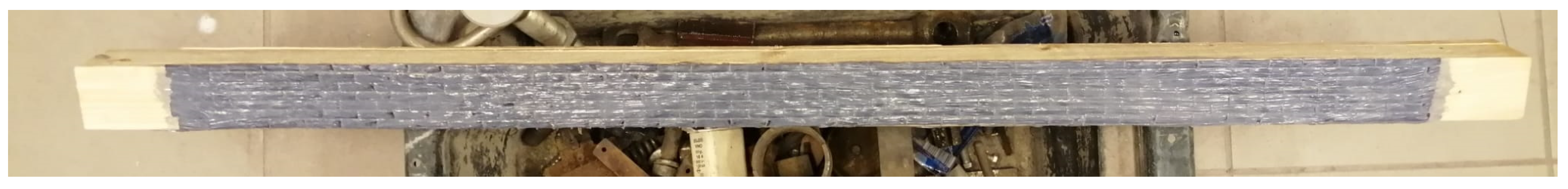
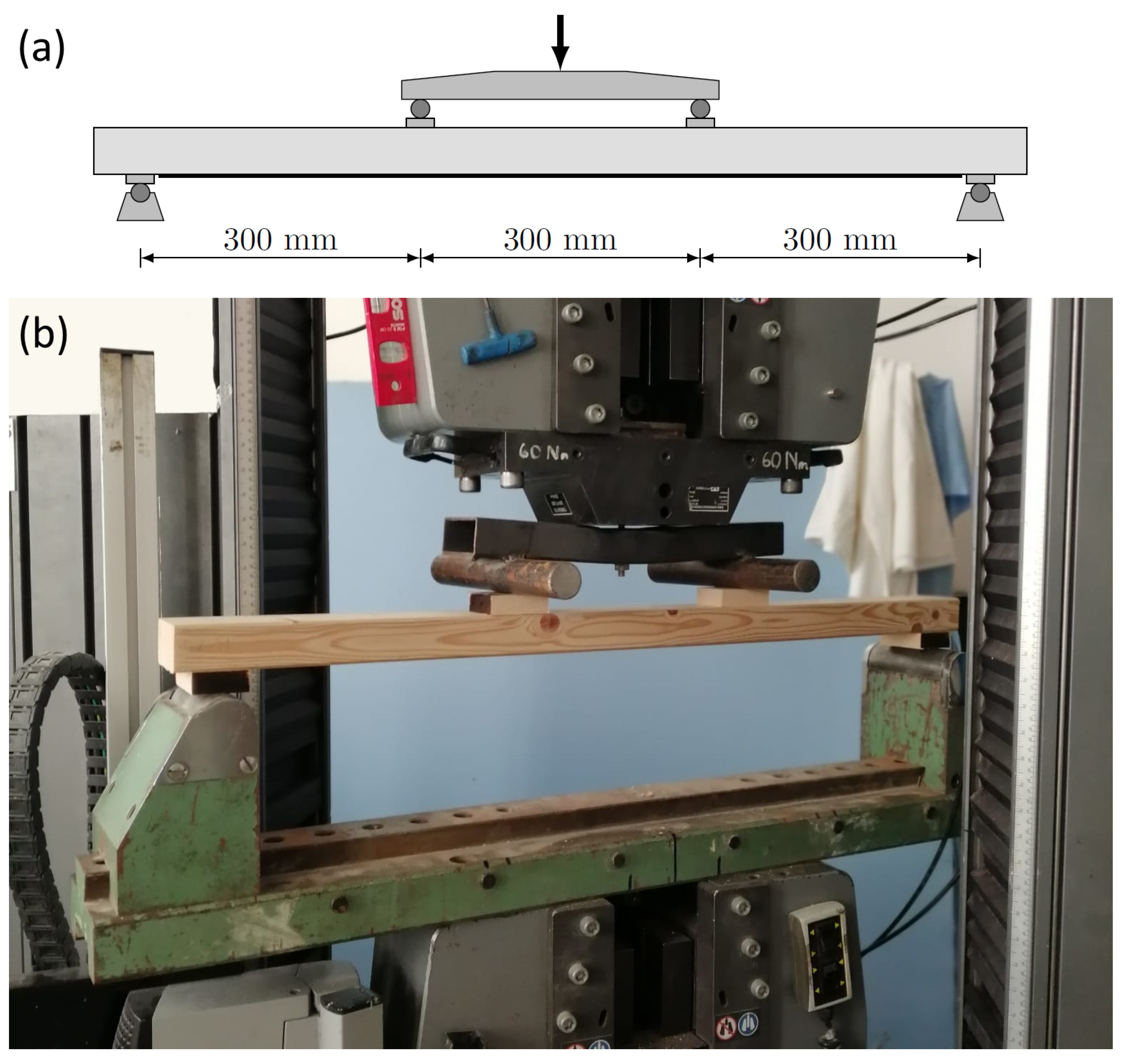
2.1. Bending Tests
2.2. Compression Tests
3. Methods
3.1. Overview
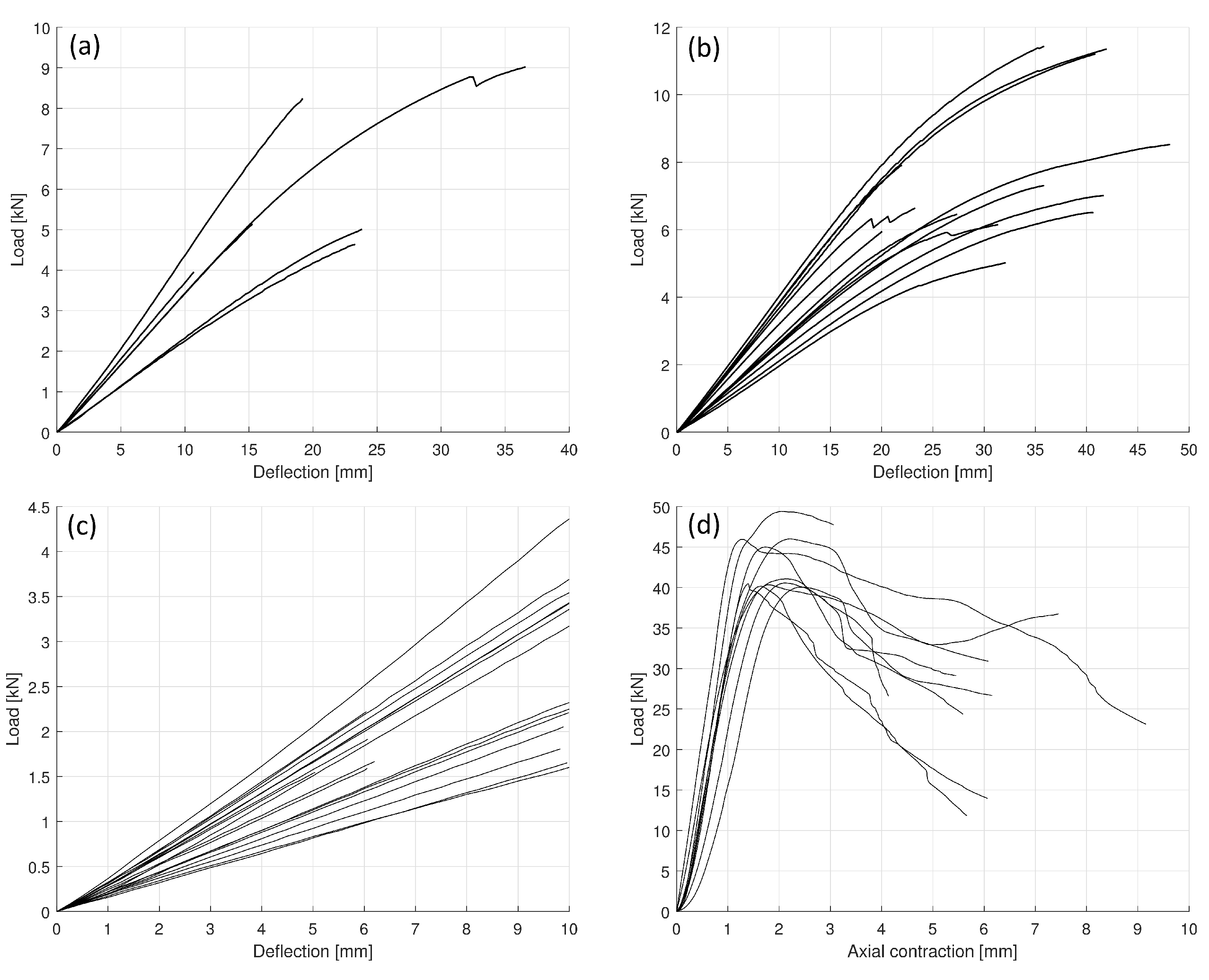
- Stiffness of all tested beams are determined by linear curve fitting to the linear sections of the load–deflection diagrams.
- Considering the classical Euler beam model, equilibrium equations of a homogeneous cross-section (for a non-reinforced beam) and of an inhomogeneous (composite) cross-section (reinforced beam) are formulated in terms of geometric data and the modulus of elasticity for timber and fibre reinforcement. In each measurement pair (same timber beam with and without reinforcement), modulus for timber can be computed from the stiffness of the non-reinforced one, and then the modulus for reinforcement from the other once the modulus for timber is known.
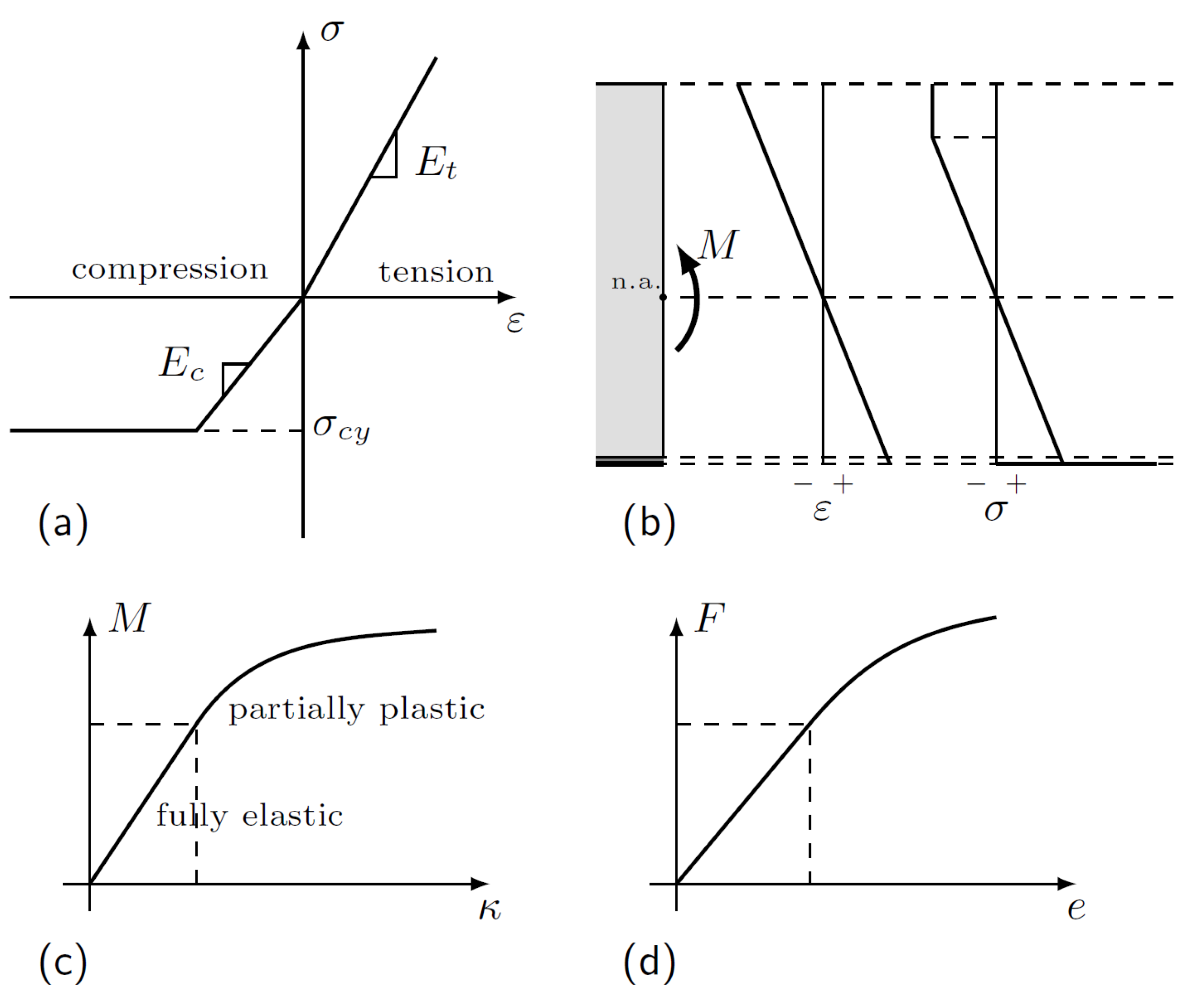
- As in several cases, the obtained modulus for reinforcement is beyond any acceptable tolerance for the factory data provided by the manufacturer, an improved model involving different moduli for tension and compression is introduced, and the equations are reformulated. With the assumption of the factory data for reinforcement, the timber moduli are computed from the equations.
- In order to cross-check the validity of computations based on the Euler beam, a three-dimensional finite element model was constructed involving a fully orthotropic material model and non-linear analysis. The two models are compared for each beam.
3.2. Analytical Considerations
3.3. Finite Element Analysis
4. Results
4.1. Stiffness
4.2. Tension and Compression Moduli
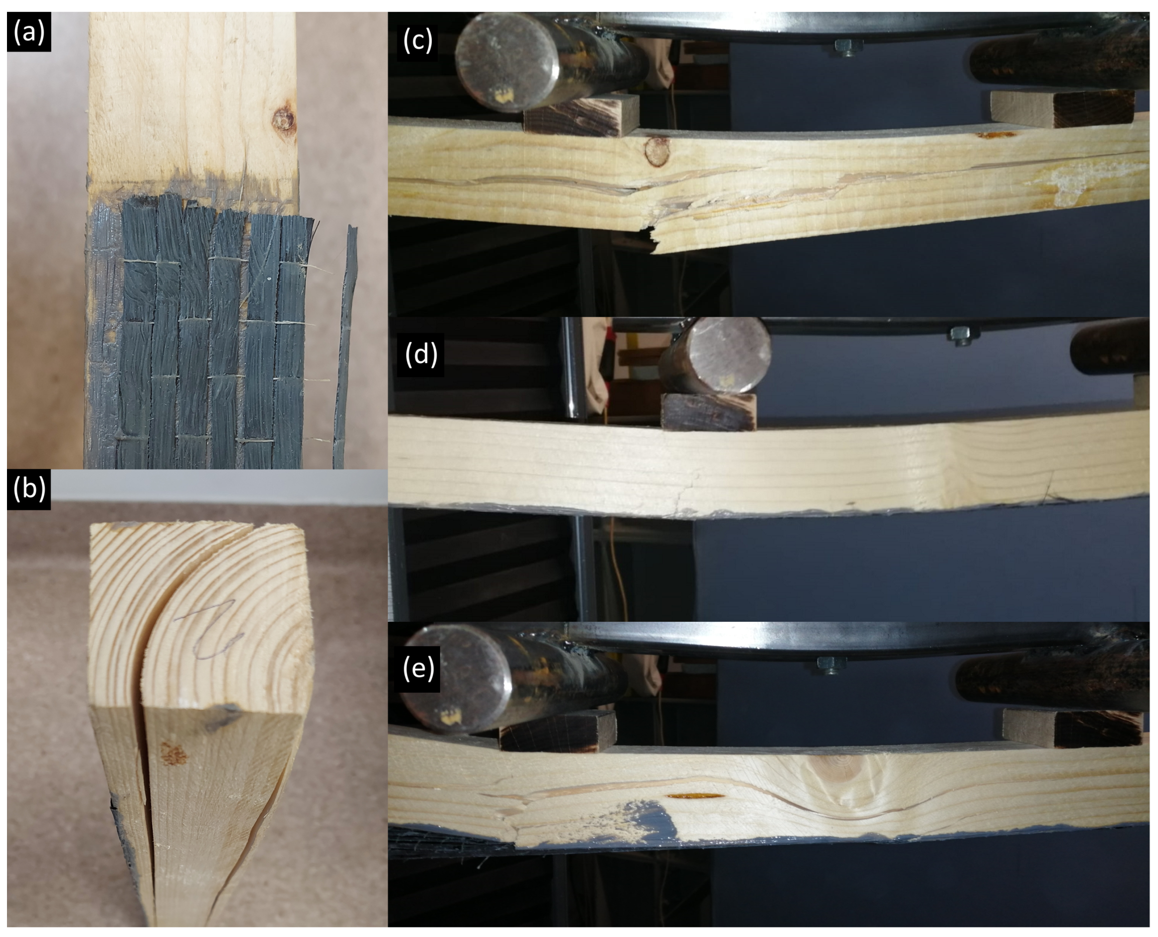
4.3. Load-Bearing Capacity and Failure
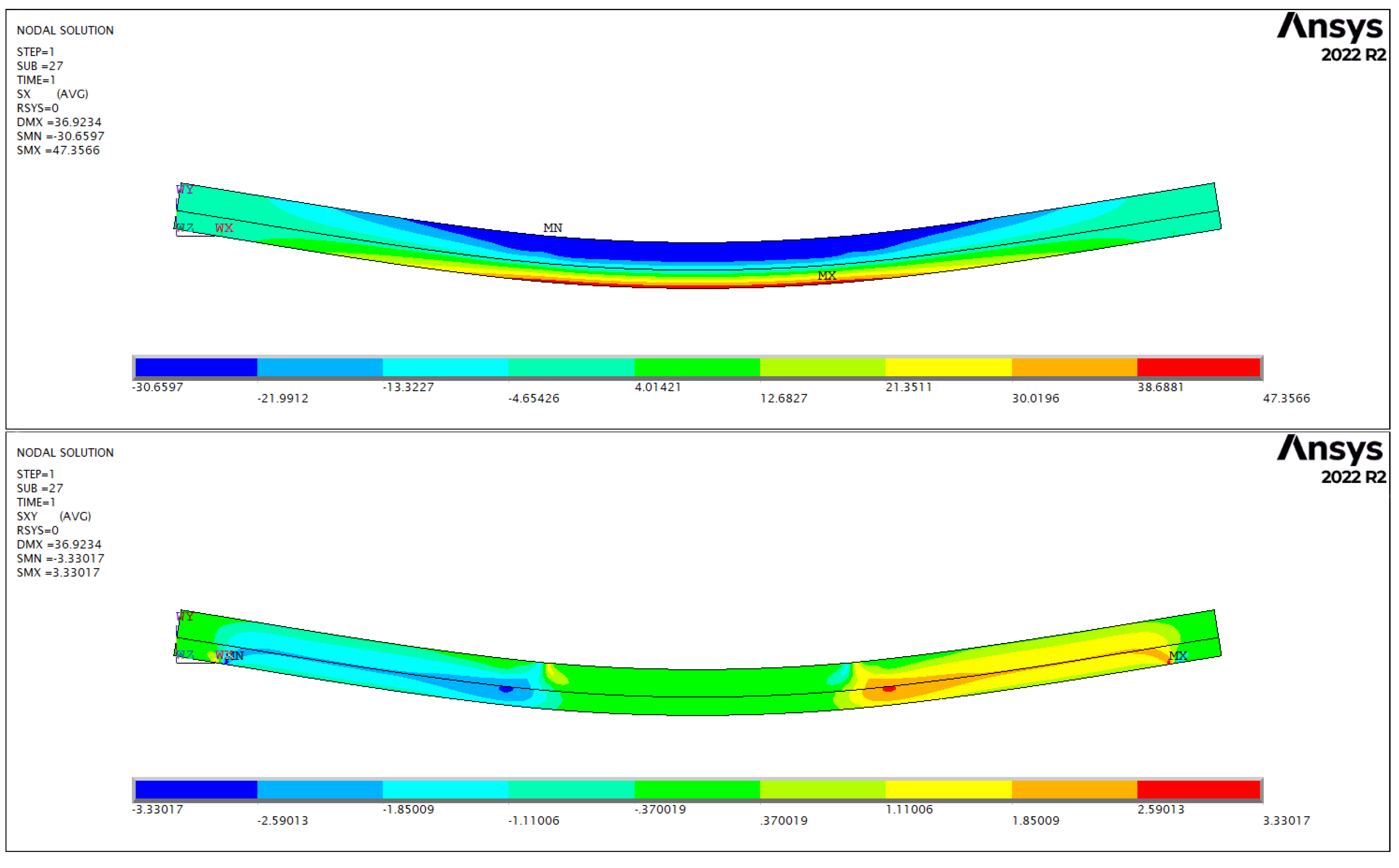
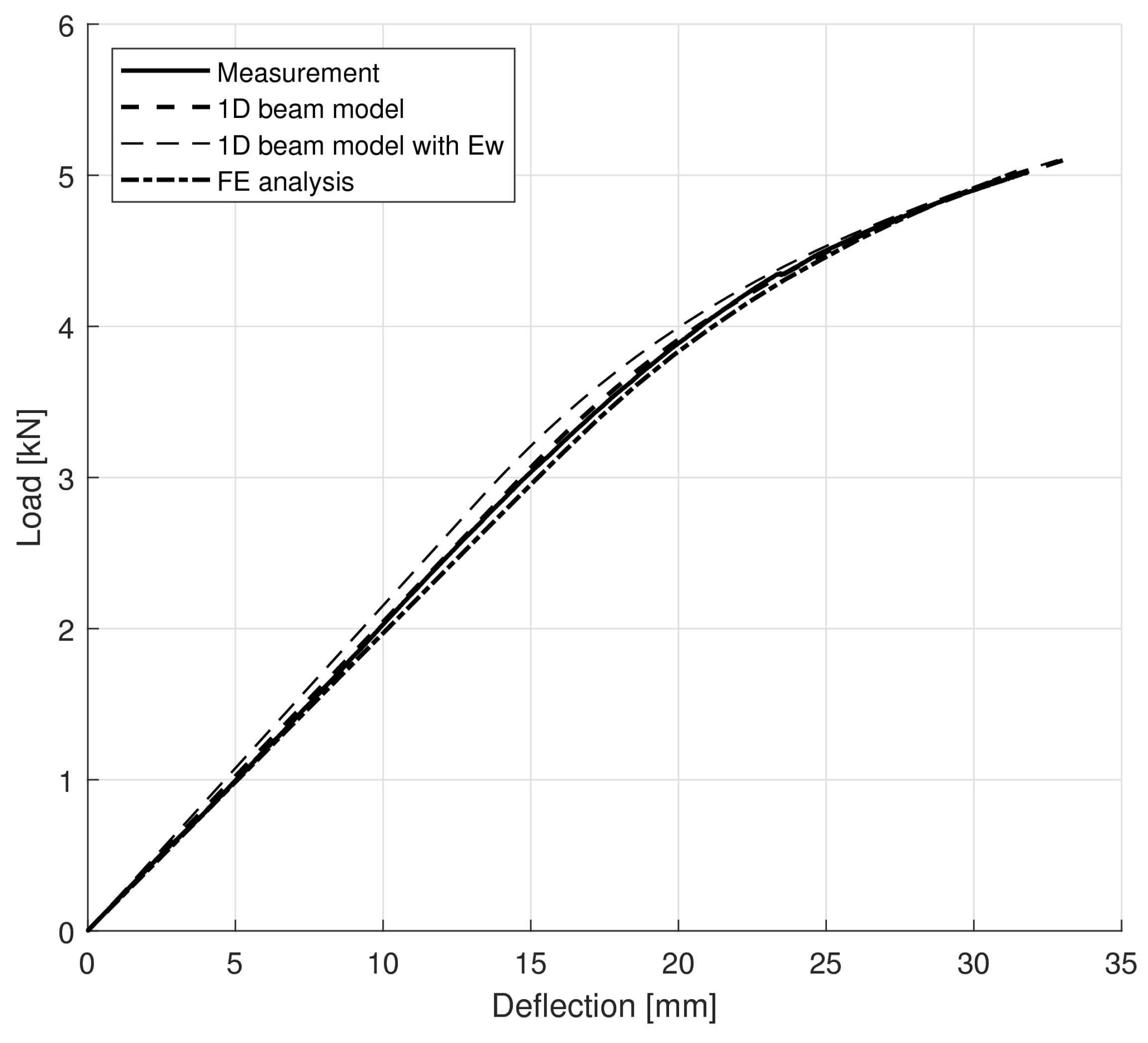
4.4. Numerical Simulations
5. Conclusions
- The adequate in situ reinforcement of non-defected timber beams produced an increase in stiffness in the range to , even with a small amount ( to volume fraction) of fibre (disregarding the failed specimens). Generally, the beams exhibited lower stiffness than expected by analytical or numerical modelling, and the differences could not be attributed to faulty or imperfect reinforcement preparation.
- Computations assuming different tension and compression moduli for timber showed in most cases that measured stiffness increase could be achieved using the nominal factory value for reinforcement modulus. Both the beam model and the finite element simulations using three-dimensional models showed good correspondence with the measured data with appropriately set compression yield stresses, indicating that the applied models are adequate for the description of the non-linear behaviour as well. The finite element simulations of the load–deflection curves resulted in an average error of in ultimate force and in compliance. The calculated compression moduli are verified by direct compression test results (mean values of GPa and GPa, respectively, with t-test showing statistical match at ). The yield stresses are also validated by the results of the axial compression tests (error of for the beam model and for the finite element model with respect to compression tests).
- Statistical comparison of stiffness values in the reinforced group with the non-reinforced reference group showed that they come from the same sample. The average increases of in load-bearing capacity, in ultimate displacement, and in compliance were achieved. These indicate that both tension and compression (with plasticity) capacities of wood could be effectively exploited and that the reinforcing technique performed adequately (with the exception of one reported case).
- The results lead to the conclusion that the differences observed between experiments and analytical considerations regarding the bending stiffness of reinforced timber beams are likely to be attributed to the use of a single modulus in timber for tension and compression, and the distinction enables adequate modelling complying with experiments.
Author Contributions
Funding
Institutional Review Board Statement
Informed Consent Statement
Data Availability Statement
Acknowledgments
Conflicts of Interest
References
- Li, C.; Guo, R.; Xian, G.; Li, H. Innovative compound-type anchorage system for a large-diameter pultruded carbon/glass hybrid rod for bridge cable. Mater. Struct. 2020, 53, 73. [Google Scholar] [CrossRef]
- Li, C.; Yin, X.; Wang, Y.; Zhang, L.; Zhang, Z.; Liu, Y.; Xian, G. Mechanical property evolution and service life prediction of pultruded carbon/glass hybrid rod exposed in harsh oil-well condition. Compos. Struct. 2020, 246, 112418. [Google Scholar] [CrossRef]
- Seifoori, S.; Mahdian Parrany, A.; Mirzarahmani, S. Impact damage detection in CFRP and GFRP curved composite laminates subjected to low-velocity impacts. Compos. Struct. 2021, 261, 113278. [Google Scholar] [CrossRef]
- Green, D.W.; Winandy, J.E.; Kretschmann, D.E. Mechanical Properties of Wood. Wood Handbook: Wood as an Engineering Material; Technical Report General Technical Report FPL; GTR-113, USDA Forest Service; Forest Products Laboratory: Madison, WI, USA, 1999.
- Rijsdijk, J.F.; Laming, P.B. Physical and Related Properties of 145 Timbers: Information for Practice; Springer Science & Business Media: Berlin/Heidelberg, Germany, 1994. [Google Scholar]
- Vallée, T.; Tannert, T.; Murcia-Delso, J.; Quinn, D.J. Influence of stress-reduction methods on the strength of adhesively bonded joints composed of orthotropic brittle adherends. Int. J. Adhes. Adhes. 2010, 30, 583–594. [Google Scholar] [CrossRef]
- Vahedian, A.; Shrestha, R.; Crews, K. Experimental and analytical investigation on CFRP strengthened glulam laminated timber beams: Full-scale experiments. Compos. Part B Eng. 2019, 164, 377–389. [Google Scholar] [CrossRef]
- Zhou, A.; Tam, L.h.; Yu, Z.; Lau, D. Effect of moisture on the mechanical properties of CFRP–wood composite: An experimental and atomistic investigation. Compos. Part B Eng. 2015, 71, 63–73. [Google Scholar] [CrossRef]
- Crews, K.; Smith, S.T. Tests on FRP strengthened timber joints. In Proceedings of the 3rd International Conference on FRP Composites in Civil Engineering. International Institute for FRP in Construction, Miami, FL, USA, 13–15 December 2006; pp. 677–680. [Google Scholar]
- Borri, A.; Corradi, M.; Grazini, A. A method for flexural reinforcement of old wood beams with CFRP materials. Compos. Part B Eng. 2005, 36, 143–153. [Google Scholar] [CrossRef]
- de Jesus, A.M.; Pinto, J.M.; Morais, J.J. Analysis of solid wood beams strengthened with CFRP laminates of distinct lengths. Constr. Build. Mater. 2012, 35, 817–828. [Google Scholar] [CrossRef]
- Andor, K.; Lengyel, A.; Polgár, R.; Fodor, T.; Karácsonyi, Z. Experimental and statistical analysis of spruce timber beams reinforced with CFRP fabric. Constr. Build. Mater. 2015, 99, 200–207. [Google Scholar] [CrossRef]
- Li, Y.F.; Xie, Y.M.; Tsai, M.J. Enhancement of the flexural performance of retrofitted wood beams using CFRP composite sheets. Constr. Build. Mater. 2009, 23, 411–422. [Google Scholar] [CrossRef]
- de la Rosa García, P.; Escamilla, A.C.; García, M.N.G. Bending reinforcement of timber beams with composite carbon fiber and basalt fiber materials. Compos. Part B Eng. 2013, 55, 528–536. [Google Scholar] [CrossRef]
- Alhayek, H.; Svecova, D. Flexural stiffness and strength of GFRP-reinforced timber beams. J. Compos. Constr. 2012, 16, 245–252. [Google Scholar] [CrossRef]
- Saad, K.; Lengyel, A. Inverse Calculation of Timber-CFRP Composite Beams Using Finite Element Analysis. Period. Polytech. Civ. Eng. 2021, 65, 437–449. [Google Scholar] [CrossRef]
- Buell, T.W.; Saadatmanesh, H. Strengthening timber bridge beams using carbon fiber. J. Struct. Eng. 2005, 131, 173–187. [Google Scholar] [CrossRef]
- Amy, K.; Svecova, D. Strengthening of dapped timber beams using glass fibre reinforced polymer bars. Can. J. Civ. Eng. 2004, 31, 943–955. [Google Scholar] [CrossRef]
- Schober, K.; Franke, S.; Rautenstrauch, K. In-Situ Strengthening of Timber Structures with CFRP; Report CIB-W18/39-12-2; Working Commission W18—Timber Structures; International Council for Research and Innovation in Building and Construction (CIB): Ottawa, ON, Canada, 2006. [Google Scholar]
- Brol, J.; Wdowiak-Postulak, A. Old Timber Reinforcement with FRPs. Materials 2019, 12, 4197. [Google Scholar] [CrossRef]
- Kent, S.; Tingley, D. Structural Evaluation of fiber reinforced hollow wood beams. In IABSE Symposium Report; International Association for Bridge and Structural Engineering: Zurich, Switzerland, 2001; Volume 85, pp. 37–42. [Google Scholar] [CrossRef]
- Johnsson, H.; Blanksvärd, T.; Carolin, A. Glulam members strengthened by carbon fibre reinforcement. Mater. Struct. 2007, 40, 47–56. [Google Scholar] [CrossRef]
- Valluzzi, M.R.; Garbin, E.; Modena, C. Flexural strengthening of timber beams by traditional and innovative techniques. J. Build. Apprais. 2007, 3, 125–143. [Google Scholar] [CrossRef]
- Rowlands, R.; Van Deweghe, R.; Laufenberg, T.L.; Krueger, G. Fiber-reinforced wood composites. Wood Fiber Sci. 1986, 18, 39–57. [Google Scholar]
- Ianasi, A. On the role of CFRP reinforcement for wood beams stiffness. In IOP Conference Series: Materials Science and Engineering; IOP Publishing: Bristol, UK, 2015; Volume 95, p. 012015. [Google Scholar] [CrossRef]
- Saad, K.; Lengyel, A. Strengthening Timber Structural Members with CFRP and GFRP: A State-of-the-Art Review. Polymers 2022, 14, 2381. [Google Scholar] [CrossRef]
- Fiorelli, J.; Dias, A.A. Analysis of the strength and stiffness of timber beams reinforced with carbon fiber and glass fiber. Mater. Res. 2003, 6, 193–202. [Google Scholar] [CrossRef]
- Gilfillan, J.; Gilbert, S.; Patrick, G. The use of FRP composites in enhancing the structural behavior of timber beams. J. Reinf. Plast. Compos. 2003, 22, 1373–1388. [Google Scholar] [CrossRef]
- Kim, Y.J.; Harries, K.A. Modeling of timber beams strengthened with various CFRP composites. Eng. Struct. 2010, 32, 3225–3234. [Google Scholar] [CrossRef]
- Raftery, G.M.; Harte, A.M. Low-grade glued laminated timber reinforced with FRP plate. Compos. Part B Eng. 2011, 42, 724–735. [Google Scholar] [CrossRef]
- Işleyen, Ü.K.; Kesik, H.İ. Experimental and numerical analysis of compression and bending strength of old wood reinforced with CFRP strips. In Structures; Elsevier: Amsterdam, The Netherlands, 2021; Volume 33, pp. 259–271. [Google Scholar]
- Dorey, A.B.; Cheng, J.R. Development of Composite Glued Laminated Timber; Natural Resources Canada, Canadian Forest Service, Northern Forestry Centre: Edmonton, AB, Canada, 1996. [Google Scholar]
- Kawecki, B.; Podgórski, J. The Effect of Glue Cohesive Stiffness on the Elastic Performance of Bent Wood–CFRP Beams. Materials 2020, 13, 5075. [Google Scholar] [CrossRef]
- Grant, D.; Anton, A.; Lind, P. Bending strength, stiffness, and stress-grade of structural Pinus radiata: Effect of knots and timber density. N. Z. J. For. Sci. 1984, 14, 331–348. [Google Scholar]
- Guindos, P.; Guaita, M. A three-dimensional wood material model to simulate the behavior of wood with any type of knot at the macro-scale. Wood Sci. Technol. 2013, 47, 585–599. [Google Scholar] [CrossRef]
- Baño, V.; Arriaga, F.; Soilán, A.; Guaita, M. Prediction of bending load capacity of timber beams using a finite element method simulation of knots and grain deviation. Biosyst. Eng. 2011, 109, 241–249. [Google Scholar] [CrossRef]
- Rescalvo, F.J.; Valverde-Palacios, I.; Suarez, E.; Gallego, A. Experimental and analytical analysis for bending load capacity of old timber beams with defects when reinforced with carbon fiber strips. Compos. Struct. 2018, 186, 29–38. [Google Scholar] [CrossRef]
- Okstad, T.; Kårstad, H. The Mechanical Properties of Spruce Wood (Picea abies L. Karst.) in Northern Norway; Meddelelser fra Norsk Institutt for Skogforskning (Norway): Oslo, Norway, 1985. [Google Scholar]
- Kristian, B.D. Mechanical Properties of Clear Wood from Norway Spruce. Ph.D. Thesis, Norwegian University of Science and Technology, Trondheim, Norway, 2009. [Google Scholar]


| Group | Reinforcement | Amount | Number | Test Type |
|---|---|---|---|---|
| 0 | none | - | 6 | total |
| F | fabrics | full span | 13 | elastic + total |
| Sp. | SN () | SR () | (%) | (GPa) | (GPa) | (GPa) | (GPa) | h (mm) | b (mm) | () |
|---|---|---|---|---|---|---|---|---|---|---|
| 0-1 | 0.2240 | 6.042 | 47.0 | 47.0 | 0.3761 | |||||
| 0-2 | 0.4285 | 12.972 | 45.4 | 46.2 | 0.5252 | |||||
| 0-3 | 0.2278 | 6.052 | 46.5 | 48.4 | 0.3725 | |||||
| 0-4 | 0.3594 | 9.743 | 46.9 | 47.4 | 0.4669 | |||||
| 0-5 | 0.3347 | 8.661 | 47.9 | 45.8 | 0.4046 | |||||
| 0-6 | 0.2262 | 7.450 | 46.0 | 42.8 | 0.5446 | |||||
| F-1 | 0.2635 | 0.2977 | 12.95 | 7.063 | 81.388 | 4.286 | 13.756 | 47.2 | 47.9 | 0.3552 |
| F-2 | 0.3114 | 0.3667 | 17.75 | 8.063 | 149.175 | 6.246 | 10.802 | 48.2 | 46.4 | 0.3617 |
| F-3 | 0.2700 | 0.2729 | 1.06 | 7.174 | −18.099 | – | – | 47.7 | 46.8 | 0.3457 |
| F-4 | 0.3730 | 0.3992 | 7.05 | 10.825 | 59.884 | – | – | 46.3 | 46.9 | 0.5275 |
| F-5 | 0.3195 | 0.3323 | 3.99 | 8.974 | 14.098 | – | – | 47.0 | 46.3 | 0.4418 |
| F-6 | 0.1592 | 0.2015 | 26.63 | 5.734 | 148.412 | 4.718 | 7.117 | 44.0 | 44.0 | 0.5262 |
| F-7 | 0.1832 | 0.2382 | 29.98 | 6.314 | 198.263 | 6.328 | 6.295 | 45.0 | 43.0 | 0.5180 |
| F-8 | 0.3595 | 0.4109 | 14.29 | 13.271 | 177.016 | 11.421 | 15.607 | 43.0 | 46.0 | 0.6020 |
| F-9 | 0.1658 | 0.2162 | 30.38 | 8.136 | 232.285 | 9.387 | 7.115 | 40.0 | 43.0 | 0.5190 |
| F-10 | 0.2080 | 0.2664 | 28.09 | 8.214 | 231.744 | 9.496 | 7.174 | 43.0 | 43.0 | 0.5237 |
| F-11 | 0.3257 | 0.3796 | 16.52 | 13.192 | 202.734 | 14.160 | 12.313 | 42.0 | 45.0 | 0.5986 |
| F-12 | 0.3381 | 0.3925 | 16.07 | 12.761 | 196.224 | 13.176 | 12.358 | 43.0 | 45.0 | 0.6443 |
| F-13 | 0.2223 | 0.2732 | 22.91 | 8.007 | 180.839 | 7.601 | 8.446 | 44.0 | 44.0 | 0.5256 |
| MOE () (GPa) | Mean | Standard Deviation |
|---|---|---|
| 0 | ||
| F |
| Compression Moduli (GPa) | Mean | Standard Deviation |
|---|---|---|
| Calculations (Equations (3), (4a), and (4b)) | ||
| Compression tests |
| Group | Max Load (kN) | Increase | Max Def. (mm) | Increase | Compliance (Nm) | Increase |
|---|---|---|---|---|---|---|
| Mean (st. dev.) | (%) | Mean (st. dev.) | (%) | Mean (st. dev.) | (%) | |
| 0 | 6.002 (2.095) | - | 21.480 (8.912) | - | 77.247 (63.899) | - |
| F | 7.623 (2.163) | +27.01 | 32.877 (9.799) | +53.06 | 180.443 (82.026) | +133.59 |
| Compression Yield Stress | Mean | Standard Deviation |
|---|---|---|
| 1D analysis | 43.20 | 15.20 |
| FE analysis | 45.65 | 17.11 |
| Compression tests | 46.37 | 3.56 |
Publisher’s Note: MDPI stays neutral with regard to jurisdictional claims in published maps and institutional affiliations. |
© 2022 by the authors. Licensee MDPI, Basel, Switzerland. This article is an open access article distributed under the terms and conditions of the Creative Commons Attribution (CC BY) license (https://creativecommons.org/licenses/by/4.0/).
Share and Cite
Saad, K.; Lengyel, A. Experimental, Analytical, and Numerical Assessments for the Controversial Elastic Stiffness Enhancement of CFRP-Strengthened Timber Beams. Polymers 2022, 14, 4222. https://doi.org/10.3390/polym14194222
Saad K, Lengyel A. Experimental, Analytical, and Numerical Assessments for the Controversial Elastic Stiffness Enhancement of CFRP-Strengthened Timber Beams. Polymers. 2022; 14(19):4222. https://doi.org/10.3390/polym14194222
Chicago/Turabian StyleSaad, Khaled, and András Lengyel. 2022. "Experimental, Analytical, and Numerical Assessments for the Controversial Elastic Stiffness Enhancement of CFRP-Strengthened Timber Beams" Polymers 14, no. 19: 4222. https://doi.org/10.3390/polym14194222
APA StyleSaad, K., & Lengyel, A. (2022). Experimental, Analytical, and Numerical Assessments for the Controversial Elastic Stiffness Enhancement of CFRP-Strengthened Timber Beams. Polymers, 14(19), 4222. https://doi.org/10.3390/polym14194222