Abstract
Perfluoropolymer membranes are widely used because of their good environmental adaptability. Herein, the ultrafine fibrous FEP porous membranes were fabricated with electrospinning-sintered technology. The effects of PVA content and sintering temperature on the fabricated membranes’ morphologies and properties were investigated. The results indicate that a kind of dimensionally stable network structure was formed in the obtained ultrafine fibrous FEP porous membranes after sintering the nascent ultrafine fibrous FEP/PVA membranes. The optimal sintering conditions were obtained by comparing the membranes’ performance in terms of membrane morphology, hydrophobicity, mechanical strength, and porosity. When the sintering temperature was 300 °C for 10 min, the porosity, water contact angle, and liquid entry pressure of the membrane were 62.7%, 124.2° ± 2.1°, and 0.18 MPa, respectively. Moreover, the ultrafine fibrous FEP porous membrane at the optimal sintering conditions was tested in vacuum membrane distillation with a permeate flux of 15.1 L·m−2·h−1 and a salt rejection of 97.99%. Consequently, the ultrafine fibrous FEP porous membrane might be applied in the seawater desalination field.
1. Introduction
The electro-spinning of nanofibers has been known since the 1930s [1]. This technique acts as a simple and versatile method that can fabricate fibers in the submicron in nanorange by an electrically charged jet of polymer solution/melt. The extensive polymers and blends also can be used to yield nanofibers [2,3,4]. Moreover, the electro-spinning differs from conventional fiber spinning that can produce cost-effective, highly porous non-woven nanofibrous membrane [5,6]. Commonly used membrane polymers such as cellulose acetate (CA) [7], polysulfone (PSf) [8], and polyvinylidenefluoride (PVDF) [9] have been successfully electro-spun to form non-woven nanofiber membranes for air and water filtrations. For example, investigations have revealed electro-spun nanofibrous membranes possess high flux rates and low transmembrane pressure [10], and hence making them potentially attractive filters in separation technology. These attractive characteristics are attributed to its (1) high porosity, (2) interconnected open pore structure, and (3) tailorable membrane thickness. Moreover, these characteristics are essential for various practical applications such as tissue engineering scaffolds [11,12,13], drug delivery [14], enzyme immobilization [15], battery membrane [16], and filtration materials [17].
Many studies are now utilizing nanoparticles and nanofibers to impart additional properties and functionalities to the membrane and also for membrane preparation and modification. Recently, many review articles in the literature have been dedicated to the application of nanotechnology to water purification [18,19,20]. Subramanian and Seeram [21] reported the developments on the use of electro-spun nanofibers for desalination application by nanofiltration (NF) and membrane distillation (MD). Feng et al. [22] reviewed the preparation and characterization of electro-spun nanofiber membranes for water treatment and other membrane separation processes. Leonard et al. [23] have recently published a comprehensive review of the use of electro-spun nanofibrous membranes for MD application. Furthermore, Zhou et al. [24] have studied vacuum membrane distillation (VMD) using polytetrafluoroethylene (PTFE) nanofiber membranes.
Recently, much research has begun to focus on the perfluoro polymer of poly(tetrafluoroethylene-co-hexafluoropropylene) (FEP), which is a random copolymer of tetrafluoroethylene (TFE) and hexafluoropropylene (HFP), including about 15 wt.% HFP [25]. As PTFE, FEP maintains the exceptional combination of outstanding thermal and chemical resistance and strong hydrophobicity owing to its perfluoro structure [26,27,28,29]. In our previous works [30], we have successfully fabricated the FEP hollow fiber membrane using the melt spinning method. However, no reports of fabricating ultrafine fibrous FEP porous membranes can be found in the past literature.
In this research, the ultrafine fibrous FEP porous membranes were fabricated with the electro-spinning process for the first time. Effects of FEP/polyvinyl alcohol (PVA) mass ratio and sintering temperature on the fabricated membranes’ morphologies and properties were investigated. The obtained ultrafine fibrous FEP porous membranes were applied in a VMD process with a permeate flux of 15.1 L·m−2·h−1 and a salt rejection of 97.99%, which exhibited a good application prospect in the field of MD or other membrane contactors (MC).
2. Experimental
2.1. Materials and Chemicals
FEP emulsion (DS603A, solid content is 50 wt.%, average diameter of FEP resin is 250 nm) was supplied by Huaxia Shenzhou New Material Co., Ltd., Zibo, China, and PVA power (1788) was purchased from Hangzhou Lanbo Industrial Co., Ltd, Hangzhou, China. Materials in this experiment were applied without further purification.
2.2. Fabrication of Ultrafine Fibrous FEP Porous Membranes
2.2.1. Preparation of Electro-Spinning Solution
The PVA aqueous solution was prepared by dissolving PVA powder in deionized water at 75 °C under constant stirring for at least 6 h. When the solution was cooled down to room temperature, a series contents of FEP emulsion was added to PVA solution with constant stirring for 4 h to form electro-spinning solutions. FEP/PVA mass ratios were 10:1, 8:1, 6:1, and 4:1, respectively, with the same solid concentration of 26 wt.%.
2.2.2. Preparation of Nascent Ultrafine Fibrous FEP/PVA Membranes
Nascent ultrafine fibrous FEP/PVA membranes were fabricated using a typical electro-spinning setup (Yizheng Wanjia Industrial Co., Ltd., Changsha, China) (Figure 1). Basically, the prepared FEP/PVA electro-spinning solution in a tube was pushed slowly into high-voltage-charged sprayers by a syringe pump with a speed 0.06 mL/h. A direct current voltage of 20 kV was applied across a distance of 15 cm between the tip of the sprayers and the grounded rotating collector which was covered by aluminum foil with a speed of 1000 rpm. During the process, ultrafine fibers were produced and collected on the rotating collector. The nascent ultrafine fibrous FEP/PVA membranes were carefully separated from the aluminum foil after steadily spinning for 4 h. Subsequently, membranes were placed in a drying oven under vacuum condition at 60 °C for over 12 h to ensure desiccation.
Figure 1.
The schematic diagram of electro-spinning apparatus.
2.2.3. Sintering Process of Nascent Ultrafine Fibrous FEP/PVA Membranes
The obtained nascent ultrafine fibrous FEP/PVA membranes were fixed in stainless steel plate, and then sintered in a muffle furnace. The furnace was heated to the target temperature with a heating rate of 10 °C/min. Since the melting point of FEP is about 256 °C., temperatures 260 °C, 280 °C, 300 °C, and 320 °C were chosen in this study, and the sintering time was 10 min at each temperature. During the sintering process, nitrogen atmosphere was maintained until the temperature was back to room temperature. Finally, the ultrafine fibrous FEP porous membranes were obtained.
2.3. Membrane Properties and Characterization
2.3.1. Morphology of Ultrafine Fibrous FEP Porous Membranes
Scanning electron microscopy (SEM, Hitachi S-4800, Tokyo, Japan)was applied to investigate the morphologies of ultrafine fibrous FEP porous membrane samples. Ultrafine fibrous FEP porous membranes were immersed in liquid N2 for 30 s and fractured. Then, samples were all coated in gold and tested in SEM. The distribution of fiber diameters was calculated in SEM images by Image Proplus software.
2.3.2. Differential Scanning Calorimeter (DSC)
The thermal properties of ultrafine fibrous FEP porous membranes were carried out using a Perkin Elmer DSC-7. The calorimeter operated under nitrogen atmosphere. Membrane samples weighing about 6 mg closed in aluminum pans were heated from up to 350 °C at 10 °C/min and then cooled to room temperature at the same rate. The crystallinity value (Xc) was calculated from the following Equation (1):
where ΔHm and ΔHm100 (87.9 J/g) represent the melting enthalpy of the investigated samples and 100% crystalline FEP, respectively.
2.3.3. Water Contact Angle (WCA)
The WCA of all the samples was measured by an optical contact angle meter (DCAT11, Dataphysics, Filderstadt, Germany), model JYSP-180) at room temperature. The diameter of the water droplet was about 1 mm, lasting for 10 s after the droplet was dropped on the sample surface by vibrating the tip of a micro-syringe. A lens and a source light were used to create the drop image on a screen. The WCA was determined with the projected drop image. Five different spots for each sample were measured. The average value of the five spots as the WCA was chosen.
2.3.4. Liquid Entry Pressure (LEP)
The optimal sintering condition was chosen to fabricate ultrafine fibrous FEP porous membranes according to the membrane properties. The LEP of dried ultrafine fibrous FEP porous membranes was accessed using a laboratory device (Figure 2) at room temperature. The pressure was slowly increased until the water seeped out, and the value of pressure gauges was the LEP. The average value of three tests as the LEP was chosen.
Figure 2.
The testing device for the LEP of the dried ultrafine fibrous FEP porous membranes.
2.3.5. Nitrogen Flux through the Membranes
Nitrogen flux of dry ultrafine fibrous FEP porous membranes was measured by a laboratory device (Figure 3) by the following Equation (2), and the permeate flow rate was measured at a pressure of 0.1 MPa.
where J is the nitrogen flux (m3·m−2·h−1), L is the nitrogen flow (m3·h−1), and A is the membrane area (m2).
Figure 3.
The testing device for the nitrogen flux of dried ultrafine fibrous FEP porous membranes.
2.3.6. Porosity and Pore Size Distribution
The gravimetric method was used for assessing the porosity by calculating the weight of liquid immersed in the membrane pores. Owing to the strong hydrophobicity of FEP, n-butyl alcohol was used as the wetting liquid. The ultrafine fibrous FEP porous membrane samples were immersed in the n-butyl alcohol for at least 24 h. The n-butyl alcohol of the membrane surface was removed by a filter paper. After that, the wet membrane’s weight was measured. Additionally, the dry membranes’ weight was measured after drying in an electric blast drying oven for 10 h at the temperature of 30 °C. The porosity (ε) was calculated by Equation (3) [22,31]:
where A is the area of the membrane (mm2), d is the average thickness of the membrane (mm), ρ is the n-butyl alcohol density (ρ = 0.811 g/mL), W1 is the weight of wet membrane (g), and W2 is the weight of the dry membrane (g).
The pore size distribution of ultrafine fibrous FEP porous membranes was investigated by using a Capillary Flow Porometer (CFP-1100-A*, Newtown Square, PA, United States). The membranes were fully wetted with the wetting liquid, and then the measurements were carried out following the procedure described in the literature [32]. The pore size distribution was determined with the aid of the computer software coupled to the capillary flow porometer.
2.3.7. Mechanical Strength
The mechanical properties of ultrafine fibrous FEP porous membranes were measured by YG-061F electronic single yarn tensile tester (Yantai, China), and 2 mm/min was used for the tensile rate. The average measurement of the five specimens was used.
2.4. VMD Experiment
Experiments on Vacuum Membrane Distillation (VMD) were carried out to evaluate the permeate performance of ultrafine fibrous FEP porous membranes. The desalination experiment was performed using a setup schematically shown in Figure 4. One side of the membrane was in contact with a hot, circulating salt solution, and its other side was connected to a vacuum pump to withdraw the permeated water vapor. The water vapor was subsequently condensed into liquid water by a glass condenser using tap water as coolant. The condensed water was collected in a glass bottle, and its volume was determined with a measuring cylinder. The conductivity of the feed solution and permeate water was measured by a conductivity meter (AP-2, HM). The NaCl rejection R was calculated by the following Equation (4):
where Cf and Cp were the conductivities of the feed solution and permeate water, respectively.
Figure 4.
Schematic diagram of the experimental VMD apparatus.
3. Results and Discussion
3.1. Membrane Morphology
3.1.1. Effects of FEP/PVA Mass Ratios
As mentioned above, the four different mass ratios of FEP/PVA (10:1, 8:1, 6:1, 4:1) were investigated in this paper. The surface morphologies of the obtained nascent ultrafine fibrous FEP porous membranes are shown in Figure 5. Owing to its insolubility in common solvents, the pure FEP could not be electro-spun into ultrafine fibers. In order to obtain nascent ultrafine fibrous FEP porous membranes, a subtractive matrix polymer and post-treatment were introduced into the process of fabricating nascent ultrafine fibrous FEP porous membranes. PVA, a water-soluble polymer, exhibits good spinnability, and it can be electro-spun into ultrafine or nano fibers easily. It was demonstrated that the nanofibers of the chitosan, hydroxyapatite, and zinc oxide were electro-spun with PVA as membrane carrier [33,34,35]. It can be found in Figure 5(A1,B1,C1,D1) that with the increasing content of PVA, nascent ultrafine fibrous FEP porous membranes obviously transformed from the beadlike structure to the fibrous structure. When the mass ratio of FEP/PVA was 10:1 (Figure 5(A1)), only a beadlike structure was obtained, while the FEP/PVA mass ratio reached 6:1 (Figure 5(C1)), and fibers of about 500 nm in diameter were formed. While increasing the PVA mass ratio further, the fiber diameters were increased. The statistics of fiber diameters were illustrated in Figure 5. The fiber diameters fluctuated in the range between 300 and 700 nm. In order to obtain nascent ultrafine fibrous porous membranes with high FEP content, PVA content should be reduced as possible on the premise of good spinnability. In this study, a FEP/PVA mass ratio of 6:1 was chosen for further investigation due to the uniform fiber diameter and pore structure.
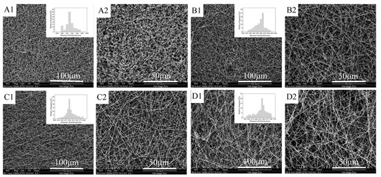
Figure 5.
Surface morphologies of nascent ultrafine fibrous FEP porous membranes at different FEP/PVA mass ratios (A): 10:1; (B): 8:1; (C): 6:1; (D): 4:1; 1: 1000× surface; 2: 2000× surface).
3.1.2. Effects of Sintering Temperature
The SEM images of ultrafine fibrous FEP porous membranes sintered at different temperatures were shown in Figure 6. From the SEM images, it can be clearly observed that the FEP particles gradually fused during the sintering process. The nascent ultrafine fibrous FEP/PVA membranes were assembled by random ultrafine fibers. The ultrafine fibers showed an interconnected fibrous network in the images (Figure 6B–D). As the sintering temperature increased, the FEP resins fused with each other furtherly, which induced not only lower membrane porosity but also smaller pore size. However, the mechanical strength of the membrane improved. Therefore, the sintering temperature is a very important factor that endows the membrane with suitable porosity and favorable mechanical strength. The membrane samples were obtained at the sintering temperature of 300 °C for 10 min. A dimensionally stable network structure was formed. Figure 6E showed the membrane which was treated at 320 °C. The fibers fused together, and the membrane presented a compact structure. Digital photos of ultrafine fibrous FEP porous membranes sintered at different temperatures are shown in Figure 6(A2,B2,C2,D2). The color of the membranes became deeper with the increase in sintering temperature.
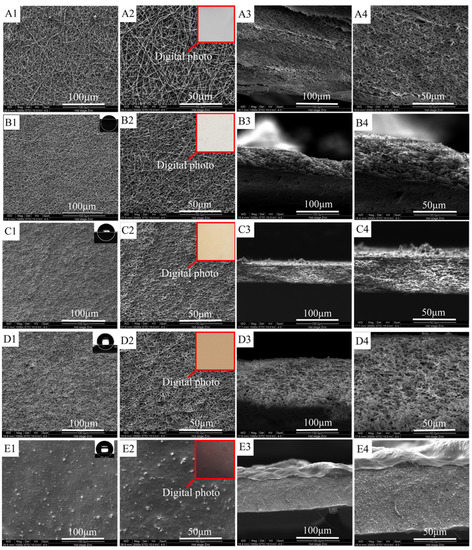
Figure 6.
Morphologies of ultrafine fibrous FEP porous membranes at different sintering temperature (FEP/PVA mass ratio 1:6; (A): nascent membrane; (B): 260 °C; (C): 280 °C; (D): 300 °C; (E): 320 °C; 1: 1000× surface; 2: 2000× surface; 3: 1000× cross-section; 4: 2000× cross-section).
3.2. DSC Analysis
Figure 7 shows the typical differential scanning calorimeter (DSC) curves of ultrafine fibrous FEP porous membrane samples, and the corresponding data were tabulated in Table 1. As shown in the heating curves (Figure 7A), there was a endothermic peak at 87.5 °C of nascent ultrafine fibrous FEP/PVA membranes. Moreover, the endothermic peak disappeared after sintering. These results indicate that the PVA was totally decomposed during the sintering process. The melting temperature of ultrafine fibrous FEP porous membranes increased with the increase in sintering temperature. Meanwhile, the enthalpy and the degree of crystallinity (Xc) increased. As for the cooling curves (Figure 7B), the crystallization peak moved towards the lower temperatures with the increase in sintering temperature. These results should be attributed to the nascent electro-spun fibers being randomly distributed and not interconnected. The sintering process enhanced the dimensional integrity and mechanical properties of the membranes.
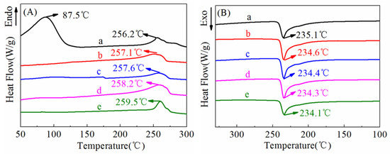
Figure 7.
DSC curves of ultrafine fibrous FEP porous membranes at different sintering temperature (FEP/PVA mass ratio: 1:6; a: nascent membrane; b: 260 °C; c: 280 °C; d: 300 °C; e: 320 °C; (A)-heating curve, (B)-cooling curve).

Table 1.
Thermal property of ultrafine fibrous FEP porous membranes by DSC.
3.3. WCA Analysis
During the MD process, hydrophobicity is one of the most important factors. As we know, the pore size, surface roughness, and composition of the membrane were the main factors to decide WCA [36]. The WCA of sintered membranes at different temperatures are shown in Figure 6 and Table 2. Due to the large pore size and PVA in the nascent ultrafine fibrous FEP/PVA membranes, it is easy to absorb a water drop into the membrane completely. However, the ultrafine fibrous FEP porous membranes exhibited strong hydrophobicity, and the WCA value increased with the increase in sintering temperature, which resulted in higher LEP and salt rejection of the MD application.
Table 2.
The data of water contact angle (n = 5).
3.4. Permeability
The porosity, N2 flux, and LEP of the ultrafine fibrous FEP porous membranes are tabulated in Table 3. As analyzed above, increased sintering temperature would induce not only lower membrane porosity but also smaller pore size, which displayed a decrease in porosity and N2 flux. It was due to the fact that the network structure became denser with the increase in sintering temperature as shown in Figure 6. Meanwhile, membrane thickness was also another factor that influenced the permeability of the fibrous membrane. Obvious differences in the thicknesses were observed among the ultrafine fibrous FEP porous membranes with different sintering temperature as listed in Table 3. The porosity of ultrafine fibrous FEP porous membranes reduced to about 60% when the sintering temperature increased above 300 °C.
Table 3.
The characteristics of the ultrafine fibrous FEP porous membranes.
N2 flux and LEP are two important membrane characteristics for MD which could provide a high MD flux. From Table 3, it can be seen that the increase in sintering temperature improved the LEP value, while the N2 flux decreased. These results should be attributed to the reduction in pore sizes and the improved hydrophobicity because of the structure of the ultrafine fiber assembling.
In this study, the ultrafine fibrous FEP porous membranes were also preferred for the MD process at the sintering temperature of 300 °C for 10 min.
3.5. Pore Size Distribution
The pore size distribution is a crucial parameter of performance during the MD process [27]. As stated by Schofield et al., the membranes utilized in MD should have a reasonably small pore size (be preferably smaller than 0.5 μm) to prevent wetting [37]. Figure 8 showed the pore size distribution curves of the ultrafine fibrous FEP porous membranes prepared from different sintering temperature. It can be found that the pore sizes of the ultrafine fibrous FEP porous membranes become smaller with the increase in sintering temperature, which agreed well with the results of SEM. The membrane sintered at 260 °C showed a broad pore size distribution ranging from 0.5 to 5.1 µm. This was due to the large fibrous network of the electro-spun fibers, as discussed in the SEM results above. When the sintering temperature was 280 °C, the pore size distribution of the ultrafine fibrous FEP porous membranes became narrower (Figure 8B). Therefore, it could be concluded that a higher sintering temperature tended to result in a smaller pore size and narrower pore size distribution (Figure 8C,D).
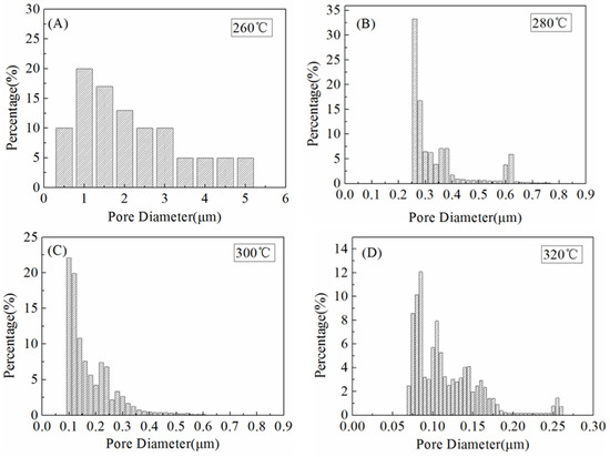
Figure 8.
Pore size distribution of the ultrafine fibrous FEP porous membranes at different sintering temperature (FEP/PVA mass ratio: 1:6). (A) 260 °C; (B) 280 °C; (C) 300 °C; (D) 320 °C
3.6. Mechanical Strength
Figure 9 shows the stress–strain curves of the ultrafine fibrous FEP porous membranes. It can be seen that the mechanical properties of the membrane samples improved significantly after sintering. These results can be explained by the structural and compositional changes at different sintering temperature. The nascent membranes were formed by multiple layers of randomly oriented composite ultrafine fibers of FEP particles in PVA matrix. However, the microstructure changed, and the FEP particles were almost completely fused when the sintering temperature was up to 320 °C. These results suggest that the changes in the microstructure observed at 260 °C was due to the melting of FEP particles, and furthermore, it also suggests that the increase in tensile strength of the ultrafine fibrous FEP porous membranes was related to the melting of FEP particles. All the changes are shown in the SEM images (Figure 6).
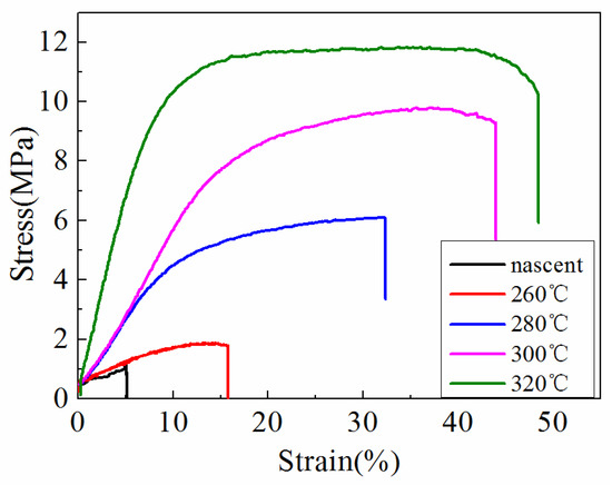
Figure 9.
Stress–strain curves of the ultrafine fibrous FEP porous membranes at different sintering temperature (FEP/PVA mass ratio: 1:6).
3.7. VMD Experiment
According to the results above, we chose the optimal sintering conditions by overall consideration of the WCA, porosity, LEP value, and mechanical strength. In the following experiments, ultrafine fibrous FEP porous membranes were prepared by sintering the nascent ultrafine fibrous FEP/PVA membranes at 300 °C for 10 min.
In the VMD process, one of the main factors is the vacuum pressure [35]. Thus, the conductivity and permeate flux were carried out by the effect of vacuum pressure. It could be seen from Figure 10 that increase in vacuum pressure induced the improvement of permeate flux. The permeate flux reached as high as 15.1 L·m−2·h−1 when vacuum pressure was 0.06 MPa while feed temperature was 80 °C, and the salt rejections achieved 97.99%, which indicated that the obtained ultrafine fibrous FEP porous membranes exhibited good application prospects in the field of MD.
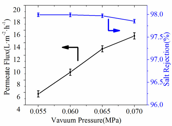
Figure 10.
Effect of vacuum pressure on the permeate flux and salt rejection (NaCl concentration, 3.5 wt.%; feed temperature, 80 °C).
Meanwhile, the effects of feed temperature are exhibited in Figure 11 with the feed temperature heated from 65 °C to 80 °C at the inlet of the membrane module. As the feed temperature increased, there was enhancement of the permeate flux in all ultrafine fibrous FEP porous membranes. It was attributed to the effect of increased feed temperature, which resulted in more mass transfer. The salt rejections of the samples also achieved 97.93%.
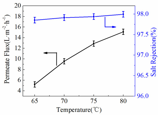
Figure 11.
Effect of feed temperature on the permeate flux and salt rejection (NaCl concentration, 3.5 wt.%; Vacuum pressure, 0.07 MPa).
3.8. Comparison with Other VMD Membranes
The results of comparisons with other MD processes are listed in Table 4. It can be observed that the permeability in this study was comparable or even better than most of the previous reports. This may be due to the fact that the porosity of the membranes was higher, and pore size was suitable for MD. Compared with ultrafine fibrous PTFE porous membrane [38], the comprehensive performances of fibrous FEP porous membrane were slightly low. However, the lower sintering temperature and lower preparation cost were the advantages of the fibrous FEP porous membrane. Moreover, owing to the excellent chemical and thermal resistance of FEP than PVDF [38,39,40], it is believed that there would be good application prospects in the field of MD, especially in systems with high temperature, acid, alkali, and other harsh environments.
Table 4.
Permeate flux in this study compared with other membranes in VMD processes.
4. Conclusions
The ultrafine fibrous FEP porous membranes used for VMD were fabricated by the electrospinning-sintering method. The optimal conditions were chosen so that the FEP/PVA mass ratio was 6:1, and sintering temperature was 300 °C for 10 min, while comparing with other preparation conditions. The membrane’s thickness, porosity, WCA, and LEP were 82 μm, 62.7%, 124.2° ± 2.1°, and 0.18 MPa, respectively, which was applied in the VMD process. The permeate flux reached as high as 15.1 L·m−2·h−1 when trans-membranous pressure was 0.06 MPa and feed temperature was 80 °C, and the salt rejections also achieved 97.99% when the feed NaCl concentration was 3.5 wt.%. Our preliminary assessment of ultrafine fibrous FEP porous membranes showed that this method has a high potential to fabricate MD membranes for desalination processes. This is of great significance for energy saving and purification in the field of seawater desalination.
Author Contributions
Writing—original draft preparation, K.C.; writing—review and editing, H.L. (Haoyang Ling); visualization, H.L. (Hailiang Liu); supervision, W.Z.; project administration, K.C. and C.X. All authors have read and agreed to the published version of the manuscript.
Funding
The National Natural Science Foundation of China (52103035, 52173038).
Institutional Review Board Statement
Not applicable.
Data Availability Statement
The data presented in this study are available on request from the corresponding author.
Acknowledgments
The authors gratefully acknowledge the research funding provided by the National Natural Science Foundation of China (52103035, 52173038).
Conflicts of Interest
The authors declare no conflict of interest.
Nomenclature
| Symbol | Definition |
| Xc | crystallinity value |
| ΔHm | melting enthalpy (J) |
| ΔHm100 | 100% melting enthalpy (J) |
| ε | porosity |
| W1 | weight of wet membrane (g) |
| W2 | the weight of dry membrane (g) |
| ρ | the density (g/mL) |
| d | the average thickness of the membrane (mm) |
| J | nitrogen flux (m3·m−2·h−1) |
| L | nitrogen flow (m3·h−1) |
| A | membrane area (m2) |
| R | rejection |
| Cf | concentration of the ink in the feed |
| Cp | concentration of the permeate solution |
References
- Formhals, A. Process and Apparatus for Preparing Artificial Threads. U.S. Patent 1,975,504, 2 October 1934. [Google Scholar]
- Parham, S.; Kharazi, A.Z.; Bakhsheshi-Rad, H.R.; Ghayour, H.; Ismail, A.F.; Nur, H.; Berto, F. Electrospun Nano-Fibers for Biomedical and Tissue Engineering Applications: A Comprehensive Review. Materials 2020, 13, 2153. [Google Scholar] [CrossRef] [PubMed]
- Hua, M.; Wu, S.; Ma, Y.; Zhao, Y.; Chen, Z.; Frenkel, I.; Strzalka, J.; Zhou, H.; Zhu, X.; He, X. Strong tough hydrogels via the synergy of freeze-casting and salting out. Nature 2021, 590, 594–599. [Google Scholar] [CrossRef]
- Li, L.; Liu, X.; Wang, G.; Liu, Y.; Kang, W.; Deng, N.; Zhuang, X.; Zhou, X. Research progress of ultrafine alumina fiber prepared by sol-gel method: A review. Chem. Eng. J. 2020, 421, 127744. [Google Scholar] [CrossRef]
- Kang, K.W.; Choi, C.W.; Jin, J.W. A Wet-Spinning Process for Producing Carbon Nanotube/Polyvinylidene Fluoride Fibers Having Highly Consistent Electrical and Mechanical Properties. Polymers 2021, 13, 4048. [Google Scholar] [CrossRef]
- Chang, L.; Wang, F.; Guo, Y.; Li, J.; Gong, Y.; Shi, Q. Green Preparation of Thermochromic Starch-Based Fibers through a Wet-Spinning Process. ACS Appl. Polym. Mater. 2020, 3, 436–444. [Google Scholar] [CrossRef]
- Lakra, R.; Balakrishnan, M.; Basu, S. Development of cellulose acetate-chitosan-metal organic framework forward osmosis membrane for recovery of water and nutrients from wastewater. J. Environ. Chem. Eng. 2021, 9, 105882. [Google Scholar] [CrossRef]
- Barambu, N.U.; Bilad, M.R.; Bustam, M.A.; Huda, N.; Jaafar, J.; Narkkun, T.; Faungnawakij, K. Development of Polysulfone Membrane via Vapor-Induced Phase Separation for Oil/Water Emulsion Filtration. Polymers 2020, 12, 2519. [Google Scholar] [CrossRef]
- Lin, Y.C.; Chao, C.M.; Wang, D.K.; Liu, K.M.; Tseng, H.H. Enhancing the antifouling properties of a PVDF membrane for protein separation by grafting branch-like zwitterions via a novel amphiphilic SMA-HEA linker. J. Membr. Sci. 2021, 624, 119126. [Google Scholar] [CrossRef]
- Wang, R.; Hu, Q.H.; Wang, Q.Y.; Xiang, Y.L.; Huang, S.H.; Liu, Y.Z.; Li, S.Y.; Chen, Q.L.; Zhou, Q.H. Efficiently selective removal of Pb(II) by magnetic ion-imprinted membrane based on polyacrylonitrile electro-spun nanofibers. Sep. Purif. Technol. 2022, 284, 120280. [Google Scholar] [CrossRef]
- Ye, S.; Zhou, X.; Xu, Y.; Lai, W.; Yan, K.; Huang, L.; Ling, J.; Zheng, L. Photocatalytic performance of multi-walled carbon nanotube/BiVO4 synthesized by electro-spinning process and its degradation mechanisms on oxytetracycline. Chem. Eng. J. 2019, 373, 880–890. [Google Scholar] [CrossRef]
- Cheng, H.; Zhou, Z.; Liu, T. Electro-spinning fabrication of nitrogen, phosphorus co-doped porous carbon nanofiber as an electro-chemiluminescent sensor for the determination of cyproheptadine. RSC Adv. 2020, 10, 23091–23096. [Google Scholar] [CrossRef] [PubMed]
- Khan, I.; Hararak, B.; Fernando, G.F. Improved procedure for electro-spinning and carbonisation of neat solvent-fractionated softwood Kraft lignin. Sci. Rep. 2021, 11, 16237. [Google Scholar] [CrossRef] [PubMed]
- Ahmadian, A.; Shafiee, A.; Aliahmad, N.; Agarwal, M. Overview of nano-fiber mats fabrication via electrospinning and morphology analysis. Textiles 2021, 1, 206–226. [Google Scholar] [CrossRef]
- Kotrotsos, A. An innovative synergy between solution electrospinning process technique and self-healing of materials. A critical review. Polym. Eng. Sci. 2021, 61, 5–21. [Google Scholar] [CrossRef]
- Rihova, M.; Ince, A.E.; Cicmancova, V.; Hromadko, L.; Castkova, K.; Pavlinak, D.; Vojtova, L.; Macak, J.M. Water-born 3D nanofiber mats using cost-effective centrifugal spinning: Comparison with electrospinning process: A complex study. J. Appl. Polym. Sci. 2021, 138, 49975. [Google Scholar] [CrossRef]
- Mailley, D.; Hebraud, A.; Schlatter, G. A review on the impact of humidity during electrospinning: From the nanofiber structure engineering to the applications. Macromol. Mater. Eng. 2021, 306, 2100115. [Google Scholar] [CrossRef]
- Kugarajah, V.; Ojha, A.K.; Ranjan, S.; Dasgupta, N.; Ganesapillai, M.; Dharmalingam, S.; Elmoll, A.; Hosseini, S.A.; Muthulakshmi, L.; Vijayakumar, S.; et al. Future applications of electrospun nanofibers in pressure driven water treatment: A brief review and research update. J. Environ. Chem. Eng. 2021, 9, 105107. [Google Scholar] [CrossRef]
- Zhang, M.; Cui, J.; Lu, T.; Tang, G.; Wu, S.; Ma, W.; Huang, C. Robust, functionalized reduced graphene-based nanofibrous membrane for contaminated water purification. Chem. Eng. J. 2021, 404, 126347. [Google Scholar] [CrossRef]
- Cao, M.; Chen, Y.; Huang, X.; Sun, L.; Xu, J.; Yang, K.; Zhao, X.; Lin, L. Construction of PA6-rGO nanofiber membrane via electrospraying combining electrospinning processes for emulsified oily sewage purification. J. Taiwan Inst. Chem. Eng. 2021, 118, 232–244. [Google Scholar] [CrossRef]
- Subramanian, S.; Seeram, R. New directions in nanofiltration applications-Are nanofibers the right materials as membranes in desalination? Desalination 2013, 308, 198–208. [Google Scholar] [CrossRef]
- Zhang, C.; Feng, F.; Zhang, H. Emulsion electrospinning: Fundamentals, food applications and prospects. Trends Food Sci. Technol. 2018, 80, 175–186. [Google Scholar] [CrossRef]
- Lett, J.A.; Sagadevan, S.; Fatimah, I.; Hoque, M.E.; Lokanathan, Y.; Léonard, E.; Alshahateet, S.F.; Schirhagl, R.; Oh, W.C. Recent advances in natural polymer-based hydroxyapatite scaffolds: Properties and applications. Eur. Polym. J. 2021, 148, 110360. [Google Scholar] [CrossRef]
- Zhou, T.; Yao, Y.; Xiang, R.; Wu, Y. Formation and characterization of polytetrafluoroethylene nanofiber membranes for vacuum membrane distillation. J. Membr. Sci. 2014, 453, 402–408. [Google Scholar] [CrossRef]
- Feng, M.; Wu, Y.; Feng, Y.; Dong, Y.; Liu, Y.; Peng, J.; Wang, N.; Xu, S.; Wang, D. Highly wearable, machine-washable, and self-cleaning fabric-based triboelectric nanogenerator for wireless drowning sensors. Nano Energy 2022, 93, 106835. [Google Scholar] [CrossRef]
- Huang, Y.; Xiao, C.; Huang, Q.; Liu, H.; Guo, Z.; Sun, K. Robust preparation of tubular PTFE/FEP ultrafine fibers-covered porous membrane by electrospinning for continuous highly effective oil/water separation. J. Membr. Sci. 2018, 568, 87–96. [Google Scholar] [CrossRef]
- Huang, Y.; Huang, Q.; Liu, H.; Xiao, C.; Sun, K. A facile and environmental-friendly strategy for preparation of poly (tetrafluoroethylene-co-hexafluoropropylene) hollow fiber membrane and its membrane emulsification performance. Chem. Eng. J. 2020, 384, 123345. [Google Scholar] [CrossRef]
- Huang, Y.; Xiao, C.; Huang, Q.; Liu, H.; Zhao, J.C. Progress on polymeric hollow fiber membrane preparation technique from the perspective of green and sustainable development. Chem. Eng. J. 2021, 403, 126295. [Google Scholar] [CrossRef]
- Hegazy, M.A.; Ghoneim, R.; Ezzat, H.A.; Yahia, I.S.; Elhaes, H.; Ibrahim, M.A. Electronic and physical studies for Teflon FEP as a thermal control in low earth orbit reinforced with ZnO and SiO2 nanoparticles. J. Mol. Model. 2021, 27, 295. [Google Scholar] [CrossRef]
- Chen, K.; Xiao, C.; Huang, Q.; Liu, H.; Liu, H.; Wu, Y.; Liu, Z. Study on vacuum membrane distillation (VMD) using FEP hollow fiber membrane. Desalination 2015, 375, 24–32. [Google Scholar] [CrossRef]
- Wu, T.; Moghadam, F.; Li, K. High-performance porous graphene oxide hollow fiber membranes with tailored pore sizes for water purification. J. Membr. Sci. 2022, 645, 120216. [Google Scholar] [CrossRef]
- Chen, H.; Li, C.; Liu, L.; Meng, B.; Yang, N.; Sunarso, J.; Liu, L.; Liu, S.; Wang, X. ZIF-67 membranes supported on porous ZnO hollow fibers for hydrogen separation from gas mixtures. J. Membr. Sci. 2022, 653, 120550. [Google Scholar] [CrossRef]
- Jahan, Z.; Niazi, M.B.K.; Hägg, M.B.; Gregersen, Ø.W. Decoupling the effect of membrane thickness and CNC concentration in PVA based nanocomposite membranes for CO2/CH4 separation. Sep. Purif. Technol. 2018, 204, 220–225. [Google Scholar] [CrossRef]
- Jahan, Z.; Niazi, M.B.K.; Hagg, M.B.; Gregersen, Ø.W.; Hussain, A. Phosphorylated nanocellulose fibrils/PVA nanocomposite membranes for biogas upgrading at higher pressure. Sep. Sci. Technol. 2020, 55, 1524–1534. [Google Scholar] [CrossRef]
- Jahan, Z.; Niazi, M.B.K.; Hägg, M.B.; Gregersen, Ø.W. Cellulose nanocrystal/PVA nanocomposite membranes for CO2/CH4 separation at high pressure. J. Membr. Sci. 2018, 554, 275–281. [Google Scholar] [CrossRef]
- Bonyadi, E.; Niknejad, A.S.; Ashtiani, F.Z.; Bazgir, S.; Kargari, A. A well-designed polystyrene/polycarbonate membrane for highly saline water desalination using DCMD process. Desalination 2022, 528, 115604. [Google Scholar] [CrossRef]
- Lalia, B.S.; Guillen-Burrieza, E.; Arafat, H.A.; Hashaikeh, R. Fabrication and characterization of polyvinylidenefluoride-co-hexafluoropropylene (PVDF-HFP) electrospun membranes for direct contact membrane distillation. J. Membr. Sci. 2013, 428, 104–115. [Google Scholar] [CrossRef]
- Nthunya, L.N.; Gutierrez, L.; Derese, S.; Nxumalo, E.N.; Verliefde, A.R.; Mamba, B.B.; Mhlanga, S.D. A review of nanoparticle-enhanced membrane distillation membranes: Membrane synthesis and applications in water treatment. J. Chem. Technol. Biotechnol. 2019, 94, 2757–2771. [Google Scholar] [CrossRef]
- Gustafson, R.D.; McGaughey, A.L.; Ding, W.; McVety, S.C.; Childress, A.E. Morphological changes and creep recovery behavior of expanded polytetrafluoroethylene (ePTFE) membranes used for membrane distillation. J. Membr. Sci. 2019, 584, 236–245. [Google Scholar] [CrossRef]
- Ramlow, H.; Ferreira, R.K.M.; Marangoni, C.; Machado RA, F. Ceramic membranes applied to membrane distillation: A comprehensive review. Int. J. Appl. Ceram. Technol. 2019, 16, 2161–2172. [Google Scholar] [CrossRef]
Publisher’s Note: MDPI stays neutral with regard to jurisdictional claims in published maps and institutional affiliations. |
© 2022 by the authors. Licensee MDPI, Basel, Switzerland. This article is an open access article distributed under the terms and conditions of the Creative Commons Attribution (CC BY) license (https://creativecommons.org/licenses/by/4.0/).