
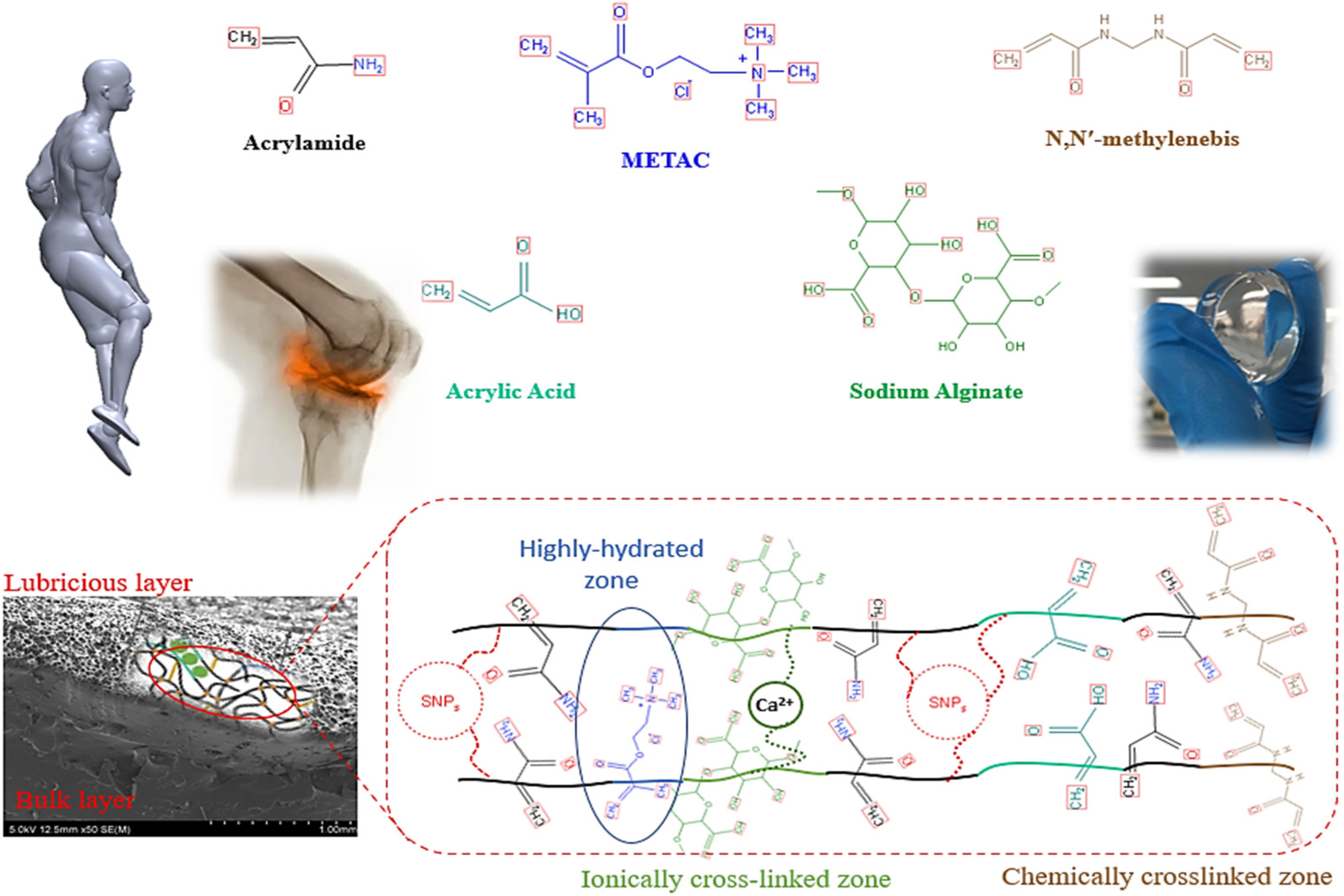
Tribological Evaluation of Silica Nanoparticle Enhanced Bilayer Hydrogels as A Candidate for Cartilage Replacement


Abstract
1. Introduction
2. Materials and Methods
2.1. Materials Preparation
2.2. Tribology Tests
2.3. Scanning Electron Microscopy
2.4. Statistical Analysis
3. Results and Discussions
3.1. Coefficient of Friction
3.2. Wear Volume
3.3. Wear Mechanisms
3.4. Lubrication Mechanisms
4. Conclusions
- Regarding tribological properties, wear resistance in the NCHs samples improved significantly, and lower CoF was observed compared to the NRHs samples.
- With respect to the lubricious layer topography and its worn surfaces, in the control sample, by increasing the load, wear mechanisms were transformed from abrasive and adhesive to fatigue phase. However, in NCHs, wear mechanisms remained intact and mostly accumulative plastic deformation was observed.
- By adding SNPs, a four-fold increase in calculated total surface energy of NCHs were achieved compared to NRHs, which remarkably affected the improvement of tribological properties.
Author Contributions
Funding
Institutional Review Board Statement
Informed Consent Statement
Data Availability Statement
Conflicts of Interest
References
- Liao, I.C.; Moutos, F.T.; Estes, B.T.; Zhao, X.; Guilak, F. Composite three-dimensional woven scaffolds with interpenetrating network hydrogels to create functional synthetic articular cartilage. Adv. Funct. Mater. 2013, 23, 5833–5839. [Google Scholar] [CrossRef] [PubMed]
- Mow Van, C.; Ratcliffe, A.; Poole Robin, A. Cartilage and diarthrodial joints as paradigms for hierarchical materials and structures. Biomaterials 1992, 13, 67–97. [Google Scholar] [CrossRef]
- Soltz, M.A.; Ateshian, G.A. A Conewise Linear Elasticity Mixture Model for the Analysis of Tension-Compression Nonlinearity in Articular Cartilage. J. Biomech. Eng. 2000, 122, 576–586. [Google Scholar] [CrossRef] [PubMed]
- Sardinha, V.M.; Lima, L.L.; Belangero, W.D.; Zavaglia, C.A.; Bavaresco, V.P.; Gomes, J.R. Tribological characterization of polyvinyl alcohol hydrogel as substitute of articular cartilage. Wear 2013, 301, 218–225. [Google Scholar] [CrossRef]
- Mayne, R. Cartilage collagens. What Is Their Function, and Are They Involved in Articular Disease? Arthritis Rheum. 1989, 32, 241–246. [Google Scholar] [CrossRef]
- Fergusson, C.M. The aetiology of osteoarthritis. Postgrad. Med. J. 1987, 63, 439–445. [Google Scholar] [CrossRef][Green Version]
- Mostakhdemin, M.; Sadegh, A.I.; Syahrom, A. Multi-Axial Fatigue of Trabecular Bone with Respect to Normal Walking; Springer: Singapore, 2016. [Google Scholar]
- Kiviranta, I.; Tammi, M.; Jurvelin, J.; Arokoski, J.; Säämänen, A.M.; Helminen, H.J. Articular cartilage thickness and glycosaminoglycan distribution in the canine knee joint after strenuous running exercise. Clin. Orthop. Relat. Res. 1992, 283, 302–308. [Google Scholar] [CrossRef]
- Vanwanseele, B.; Lucchinetti, E.; Stüssi, E. The effects of immobilization on the characteristics of articular cartilage: Current concepts and future directions. Osteoarthr. Cartil. 2002, 10, 408–419. [Google Scholar] [CrossRef]
- Arjmandi, M.; Ramezani, M.; Nand, A.; Neitzert, T. Experimental study on friction and wear properties of interpenetrating polymer network alginate-polyacrylamide hydrogels for use in minimally-invasive joint implants. Wear 2018, 406–407, 194–204. [Google Scholar] [CrossRef]
- Ronken, S.; Wirz, D.; Daniels, A.U.; Kurokawa, T.; Gong, J.P.; Arnold, M.P. Double-network acrylamide hydrogel compositions adapted to achieve cartilage-like dynamic stiffness. Biomech. Modeling Mechanobiol. 2013, 12, 243–248. [Google Scholar] [CrossRef]
- Kotaro, H.; Nobuto, K.; Keiko, G.; Takayuki, K.; Ping, G.J.; Fuminori, K.; Kazunori, Y. Effects of osteochondral defect size on cartilage regeneration using a double-network hydrogel. BMC Musculoskelet. Disord. 2017, 18, 210. [Google Scholar] [CrossRef]
- Mohammad, M.; Ashveen, N.; Mohammadreza, A.; Maziar, R. Mechanical and microscopical characterisation of bilayer hydrogels strengthened by TiO2 nanoparticles as a cartilage replacement candidate. Mater. Today Commun. 2020, 25, 101279. [Google Scholar] [CrossRef]
- Redaelli, F.; Sorbona, M.; Rossi, F. 10-Synthesis and processing of hydrogels for medical applications. In Bioresorbable Polymers for Biomedical Applications; Perale, G., Hilborn, J., Eds.; Woodhead Publishing: Sawston, UK, 2017. [Google Scholar] [CrossRef]
- Li, L.; Yu, F.; Zheng, L.; Wang, R.; Yan, W.; Wang, Z.; Xu, J.; Wu, J.; Shi, D.; Zhu, L.; et al. Natural hydrogels for cartilage regeneration: Modification, preparation and application. J. Orthop. Transl. 2019, 17, 26–41. [Google Scholar] [CrossRef]
- Ozawa, F.; Okitsu, T.; Takeuchi, S. Improvement in the Mechanical Properties of Cell-Laden Hydrogel Microfibers Using Interpenetrating Polymer Networks. ACS Biomater. Sci. Eng. 2017, 3, 392–398. [Google Scholar] [CrossRef] [PubMed]
- Kitiri, E.N.; Varnava, C.K.; Patrickios, C.S.; Voutouri, C.; Stylianopoulos, T.; Gradzielski, M.; Hoffmann, I. Double-networks based on interconnected amphiphilic “in–out” star first polymer conetworks prepared by RAFT polymerization. J. Polym. Sci. Part A Polym. Chem. 2018, 56, 2161–2174. [Google Scholar] [CrossRef]
- Buxton, A.N.; Zhu, J.; Marchant, R.; West, J.L.; Yoo, J.U.; Johnstone, B. Design and Characterization of Poly(Ethylene Glycol) Photopolymerizable Semi-Interpenetrating Networks for Chondrogenesis of Human Mesenchymal Stem Cells. Tissue Eng. 2007, 13, 2549–2560. [Google Scholar] [CrossRef] [PubMed]
- Rahim, F.; Alireza, K.; Ata, H.; Hossein, Y.; Mahdi, N. Influence of Poly(acrylic acid) on the Mechanical Properties of Composite Hydrogels. Adv. Polym. Technol. 2015, 34, 21487. [Google Scholar] [CrossRef]
- Zhang, R.; Lin, P.; Yang, W.; Cai, M.; Yu, B.; Zhou, F. Simultaneous superior lubrication and high load bearing by the dynamic weak interaction of a lubricant with mechanically strong bilayer porous hydrogels. Polym. Chem. 2017, 8, 7102–7107. [Google Scholar] [CrossRef]
- Li, Y.; Rodrigues, J.; Tomás, H. Injectable and biodegradable hydrogels: Gelation, biodegradation and biomedical applications. Chem. Soc. Rev. 2012, 41, 2193–2221. [Google Scholar] [CrossRef]
- Jaiswal Manish, K.; Xavier Janet, R.; Carrow James, K.; Desai, P.; Alge, D.; Gaharwar Akhilesh, K. Mechanically Stiff Nanocomposite Hydrogels at Ultralow Nanoparticle Content. ACS Nano 2016, 10, 246–256. [Google Scholar] [CrossRef]
- Suzan, A.; Volkan, C.; Oguz, O. Equilibrium swelling behavior and elastic properties of polymer–clay nanocomposite hydrogels. J. Appl. Polym. Sci. 2008, 109, 3714–3724. [Google Scholar] [CrossRef]
- Toledo, L.; Racine, L.; Pérez, V.; Henríquez, J.P.; Auzely-Velty, R.; Urbano Bruno, F. Physical nanocomposite hydrogels filled with low concentrations of TiO2 nanoparticles: Swelling, networks parameters and cell retention studies. Mater. Sci. Eng. C 2018, 92, 769–778. [Google Scholar] [CrossRef] [PubMed]
- Janet, D.; Pearl, M.D. Diagram-of-Osteoarthritis-in-Knee-Joint. Available online: https://www.completepaincare.com/patient-education/conditions-treated/elbow-pain/diagram-of-osteoarthritis-in-knee-joint/ (accessed on 16 March 2020).
- Zareie, C.; Bahramian, A.R.; Sefti, M.V.; Salehi, M.B. Network-gel strength relationship and performance improvement of polyacrylamide hydrogel using nano-silica; with regards to application in oil wells conditions. J. Mol. Liq. 2019, 278, 512–520. [Google Scholar] [CrossRef]
- Mohammadreza, A.; Maziar, R. Mechanical and tribological assessment of silica nanoparticle-alginate-polyacrylamide nanocomposite hydrogels as a cartilage replacement. J. Mech. Behav. Biomed. Mater. 2019, 95, 196–204. [Google Scholar] [CrossRef]
- Zhan, Y.; Pan, Y.; Chen, B.; Lu, J.; Zhong, Z.; Niu, X. Strain rate dependent hyperelastic stress-stretch behavior of a silica nanoparticle reinforced poly (ethylene glycol) diacrylate nanocomposite hydrogel. J. Mech. Behav. Biomed. Mater. 2017, 75, 236–243. [Google Scholar] [CrossRef] [PubMed]
- Mao, Y.; Lin, S.; Zhao, X.; Anand, L. A large deformation viscoelastic model for double-network hydrogels. J. Mech. Phys. Solids 2017, 100, 103–130. [Google Scholar] [CrossRef]
- Adibnia, V.; Hill Reghan, J. Viscoelasticity of near-critical silica-polyacrylamide hydrogel nanocomposites. Polymer 2017, 112, 457–465. [Google Scholar] [CrossRef]
- Wahlquist Joseph, A.; DelRio Frank, W.; Randolph Mark, A.; Aziz Aaron, H.; Heveran Chelsea, M.; Bryant Stephanie, J.; Neu Corey, P.; Ferguson Virginia, L. Indentation mapping revealed poroelastic, but not viscoelastic, properties spanning native zonal articular cartilage. Acta Biomater. 2017, 64, 41–49. [Google Scholar] [CrossRef]
- Taffetani, M.; Gottardi, R.; Gastaldi, D.; Raiteri, R.; Vena, P. Poroelastic response of articular cartilage by nanoindentation creep tests at different characteristic lengths. Med. Eng. Phys. 2014, 36, 850–858. [Google Scholar] [CrossRef]
- Mohammadreza, A.; Maziar, R. Effect of Silica Nanoparticles on Wear Mechanism of Alginate-Polyacrylamide Hydrogel Matrix as a Load-Bearing Biomaterial. Mater. Sci. Eng. 2019, 823, 15–20. [Google Scholar] [CrossRef]
- Covert Rebeccah, J.; Ott, R.D.; Ku David, N. Friction characteristics of a potential articular cartilage biomaterial. Wear 2003, 255, 1064–1068. [Google Scholar] [CrossRef]
- Moeendarbary, E.; Valon, L.; Fritzsche, M.; Harris, A.R.; Moulding, D.A.; Thrasher, A.J.; Stride, E.; Mahadevan, L.; Charras, G.T. The cytoplasm of living cells behaves as a poroelastic material. Nat. Mater. 2013, 12, 253–261. [Google Scholar] [CrossRef]
- Brand Richard, A. Joint contact stress: A reasonable surrogate for biological processes? Iowa Orthop. J. 2005, 25, 82–94. [Google Scholar]
- Pickard, J.; Ingham, E.; Egan, J.; Fisher, J. Investigation into the effect of proteoglycan molecules on the tribological properties of cartilage joint tissues. Proc. Inst. Mech. Eng. Part H J. Eng. Med. 1998, 212, 177–182. [Google Scholar] [CrossRef] [PubMed]
- Katta, J.; Pawaskar, S.S.; Jin, Z.M.; Ingham, E.; Fisher, J. Effect of load variation on the friction properties of articular cartilage. Proc. Inst. Mech. Eng. Part J J. Eng. Tribol. 2007, 221, 175–181. [Google Scholar] [CrossRef]
- Katta, J.; Jin, Z.; Ingham, E.; Fisher, J. Friction and wear of native and GAG deficient articular cartilage. In Proceedings of the World Biomaterials Congress, Amsterdam, The Netherlands, 28 May–1 June 2008; p. 1191. [Google Scholar]
- Gombert, Y.; Simič, R.; Roncoroni, F.; Dübner, M.; Geue, T.; Spencer, N.D. Structuring Hydrogel Surfaces for Tribology. Adv. Mater. Interfaces 2019, 6, 1901320. [Google Scholar] [CrossRef]
- Link Jarrett, M.; Salinas Evelia, Y.; Hu Jerry, C.; Athanasiou Kyriacos, A. The tribology of cartilage: Mechanisms, experimental techniques, and relevance to translational tissue engineering. Clin. Biomech. 2019, 79, 104880. [Google Scholar] [CrossRef]
- Urueña, J.M.; Pitenis Angela, A.; Nixon Ryan, M.; Schulze Kyle, D.; Angelini Thomas, E.; Gregory Sawyer, W. Mesh Size Control of Polymer Fluctuation Lubrication in Gemini Hydrogels. Biotribology 2015, 1–2, 24–29. [Google Scholar] [CrossRef]
- Pitenis, A.A.; Urueña, J.M.; Schulze, K.D.; Nixon, R.M.; Dunn, A.C.; Krick, B.A.; Sawyer, W.G.; Angelini, T.E. Polymer fluctuation lubrication in hydrogel gemini interfaces. Soft Matter 2014, 10, 8955–8962. [Google Scholar] [CrossRef]
- Dunn, A.C.; Sawyer, W.G.; Angelini, T.E. Gemini Interfaces in Aqueous Lubrication with Hydrogels. Tribol. Lett. 2014, 54, 59–66. [Google Scholar] [CrossRef]
- Forster, H.; Fisher, J. The Influence of Loading Time and Lubricant on the Friction of Articular Cartilage. Proc. Inst. Mech. Eng. Part H J. Eng. Med. 1996, 210, 109–119. [Google Scholar] [CrossRef] [PubMed]
- Lai, W.M.; Hou, J.S.; Mow, V.C. A Triphasic Theory for the Swelling and Deformation Behaviors of Articular Cartilage. J. Biomech. Eng. 1991, 113, 245–258. [Google Scholar] [CrossRef] [PubMed]
- Bell, C.J.; Ingham, E.; Fisher, J. Influence of hyaluronic acid on the time-dependent friction response of articular cartilage under different conditions. Proc. Inst. Mech. Eng. Part H J. Eng. Med. 2006, 220, 23–31. [Google Scholar] [CrossRef] [PubMed]
- Lin, P.; Zhang, R.; Wang, X.; Cai, M.; Yang, J.; Yu, B.; Zhou, F. Articular Cartilage Inspired Bilayer Tough Hydrogel Prepared by Interfacial Modulated Polymerization Showing Excellent Combination of High Load-Bearing and Low Friction Performance. ACS Macro Lett. 2016, 5, 1191–1195. [Google Scholar] [CrossRef]
- Mostakhdemin, M.; Nand, A.; Ramezani, M. A novel assessment of microstructural and mechanical behaviour of bilayer silica-reinforced nanocomposite hydrogels as a candidate for artificial cartilage. J. Mech. Behav. Biomed. Mater. 2021, 116, 104333. [Google Scholar] [CrossRef]
- Li, F.; Wang, A.; Wang, C. Analysis of friction between articular cartilage and polyvinyl alcohol hydrogel artificial cartilage. J. Mater. Sci. Mater. Med. 2016, 27, 87. [Google Scholar] [CrossRef]
- Gong, J.; Osada, Y. Gel friction: A model based on surface repulsion and adsorption. J. Chem. Phys. 1998, 109, 8062–8068. [Google Scholar] [CrossRef]
- Korres, S.; Sorochynska, L.; Grishchuk, S.; Karger-Kocsis, J. Swelling, compression and tribological behaviors of bentonite-modified polyacrylate-type hydrogels. J. Appl. Polym. Sci. 2011, 119, 1122–1134. [Google Scholar] [CrossRef]
- Yutaka, O.; Rikiya, T.; Ping, G.J.; Yoshihito, O. Surface Friction of Hydrogels with Well-Defined Polyelectrolyte Brushes. Langmuir 2004, 20, 6549–6555. [Google Scholar] [CrossRef]
- Ab Rahman, I.; Padavettan, V. Synthesis of Silica Nanoparticles by Sol-Gel: Size-Dependent Properties, Surface Modification, and Applications in Silica-Polymer Nanocomposites—A Review. J. Nanomater. 2012, 2012, 8. [Google Scholar] [CrossRef]
- Kenneth, L.J.; Kevin, K.; Roberts, A.D. Surface energy and the contact of elastic solids. Proc. R. Soc. A 1971, 324, 301–313. [Google Scholar] [CrossRef]
- Li, H.; Choi, Y.S.; Rutland, M.W.; Atkin, R. Nanotribology of hydrogels with similar stiffness but different polymer and crosslinker concentrations. J. Colloid Interface Sci. 2020, 563, 347–353. [Google Scholar] [CrossRef] [PubMed]
- Jiho, K.; Alison, C.D. Soft hydrated sliding interfaces as complex fluids. Soft Matter 2016, 12, 6536–6546. [Google Scholar] [CrossRef]
- Yang, J.; Zhao, J. Preparation and mechanical properties of silica nanoparticles reinforced composite hydrogels. Mater. Lett. 2014, 120, 36–38. [Google Scholar] [CrossRef]
- Yang, J.; Wang, X.-P.; Xie, X.-M. In situ synthesis of poly(acrylic acid) physical hydrogels from silica nanoparticles. Soft Matter 2012, 8, 1058–1063. [Google Scholar] [CrossRef]
- Bonyadi Shabnam, Z.; Dunn Alison, C. Brittle or Ductile? Abrasive Wear of Polyacrylamide Hydrogels Reveals Load-Dependent Wear Mechanisms. Tribol. Lett. 2020, 68, 16. [Google Scholar] [CrossRef]
- Schmidt Tannin, A.; Gastelum Nicholas, S.; Nguyen Quynhhoa, T.; Schumacher Barbara, L.; Sah Robert, L. Boundary lubrication of articular cartilage: Role of synovial fluid constituents. Arthritis Rheum. 2007, 56, 882–891. [Google Scholar] [CrossRef]


| Experiments Sets | Test Parameters | Contact Conditions | |
|---|---|---|---|
| Set 1 (NRHs and NCHs) | 0.5 N | Constant sliding speed [80 mm/s] | Dry and Lubricated |
| 0.7 N | |||
| 0.9 N | |||
| Set 2 (NRHs and NCHs) | 50 mm/s | Constant load [0.7 N] | |
| 80 mm/s | |||
| 110 mm/s | |||
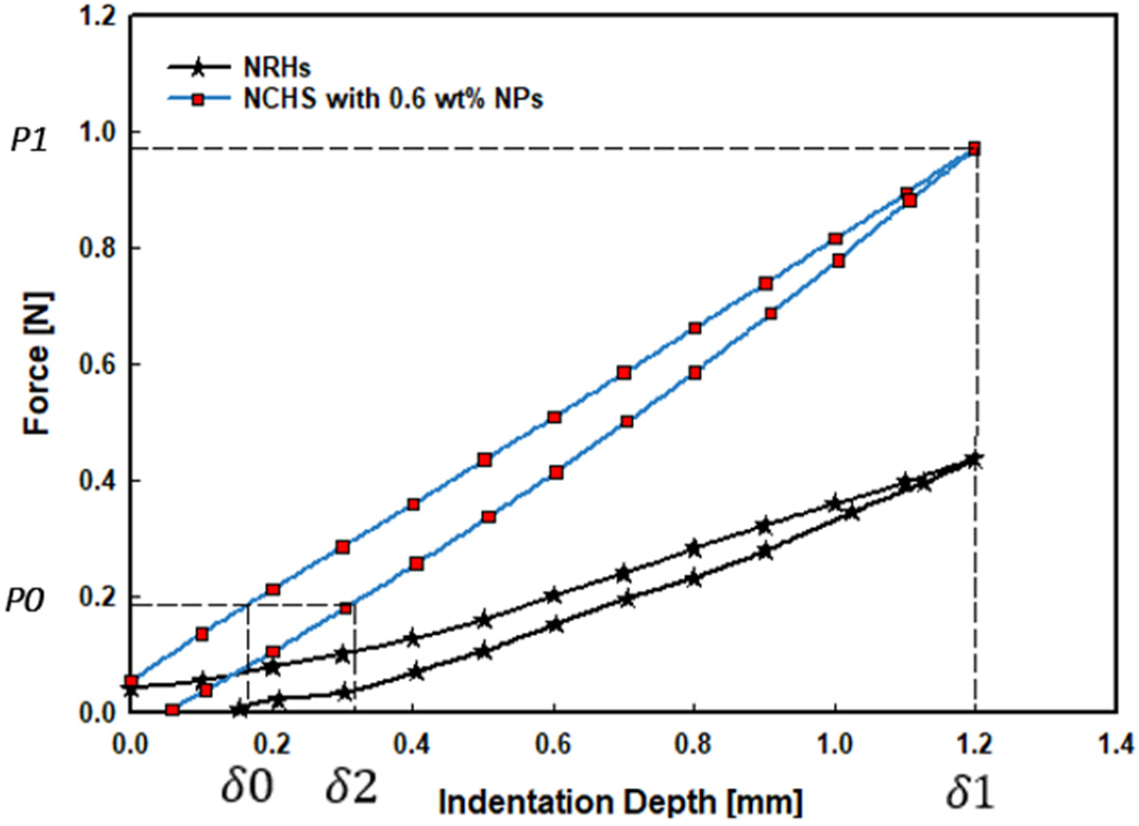
| Variables | NRHs | NCHs |
|---|---|---|
| Elastic modulus (E) | 150 kPa | 240 kPa |
| Poisson’s ratio (v) | 0.5 | 0.5 |
| R | 0.7 mm | 0.5 mm |
| P0 | 0.1 N | 0.2 N |
| P1 | 0.4 N | 1.0 N |
| δ1 | 1.2 mm | 1.2 mm |
| δ2 | 0.4 mm | 0.35 mm |
| δ0 | 0.2 mm | 0.18 mm |
| US | 34.22 | 170.88 |
| UE | 11.28 | 62.34 |
| UM | 0.035 | 0.164 |
| UT | 22.97 | 108.71 |
Publisher’s Note: MDPI stays neutral with regard to jurisdictional claims in published maps and institutional affiliations. |
© 2022 by the authors. Licensee MDPI, Basel, Switzerland. This article is an open access article distributed under the terms and conditions of the Creative Commons Attribution (CC BY) license (https://creativecommons.org/licenses/by/4.0/).
Share and Cite
Mostakhdemin, M.; Nand, A.; Ramezani, M. Tribological Evaluation of Silica Nanoparticle Enhanced Bilayer Hydrogels as A Candidate for Cartilage Replacement. Polymers 2022, 14, 3593. https://doi.org/10.3390/polym14173593
Mostakhdemin M, Nand A, Ramezani M. Tribological Evaluation of Silica Nanoparticle Enhanced Bilayer Hydrogels as A Candidate for Cartilage Replacement. Polymers. 2022; 14(17):3593. https://doi.org/10.3390/polym14173593
Chicago/Turabian StyleMostakhdemin, Mohammad, Ashveen Nand, and Maziar Ramezani. 2022. "Tribological Evaluation of Silica Nanoparticle Enhanced Bilayer Hydrogels as A Candidate for Cartilage Replacement" Polymers 14, no. 17: 3593. https://doi.org/10.3390/polym14173593
APA StyleMostakhdemin, M., Nand, A., & Ramezani, M. (2022). Tribological Evaluation of Silica Nanoparticle Enhanced Bilayer Hydrogels as A Candidate for Cartilage Replacement. Polymers, 14(17), 3593. https://doi.org/10.3390/polym14173593