
Effects of Polyoxymethylene Fiber on Mechanical Properties of Seawater Sea-Sand Concrete with Different Ages


Abstract
:1. Introduction
2. Property of Material
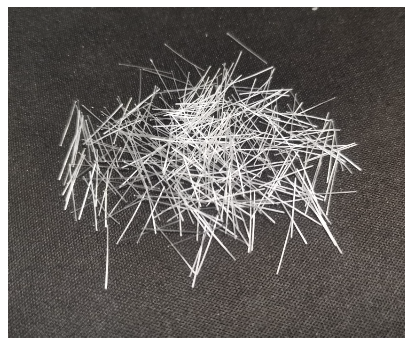
2.1. POM Fiber
2.2. Sea–Sand and Seawater
2.3. Concrete Mixture
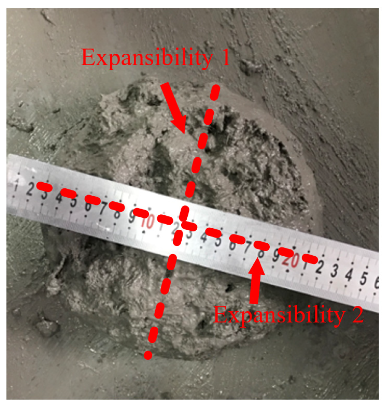
3. Workability
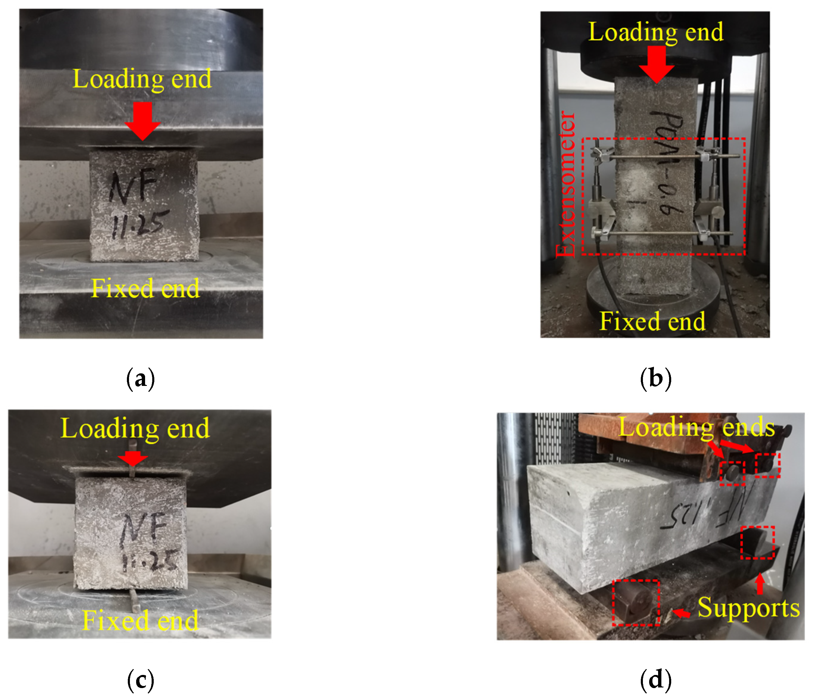
4. Mechanical Test Procedure
5. Mechanical Test Results
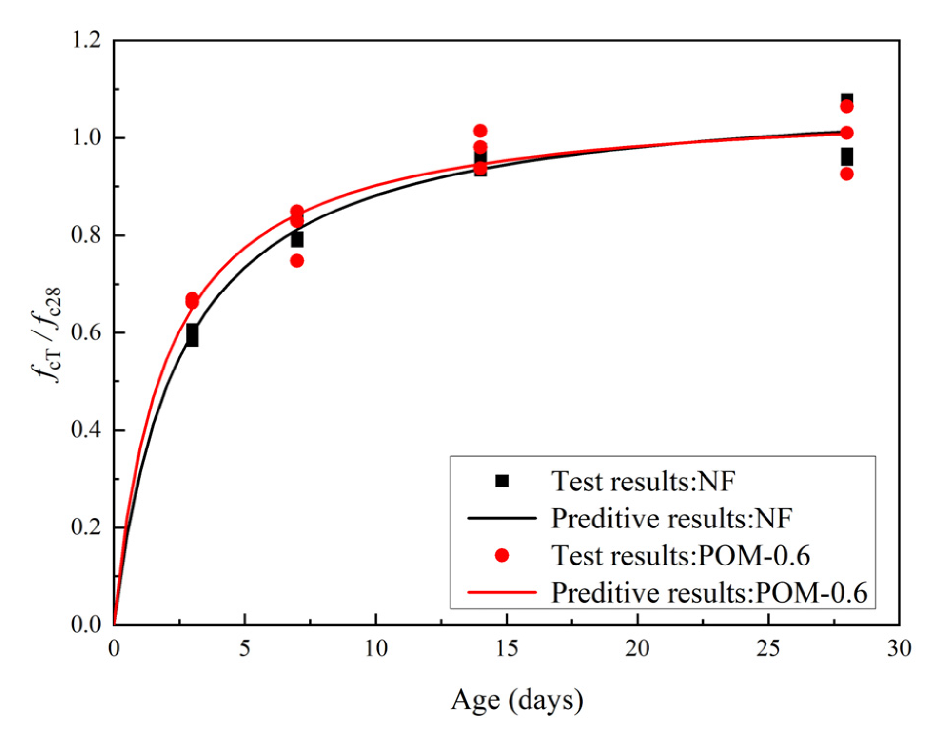
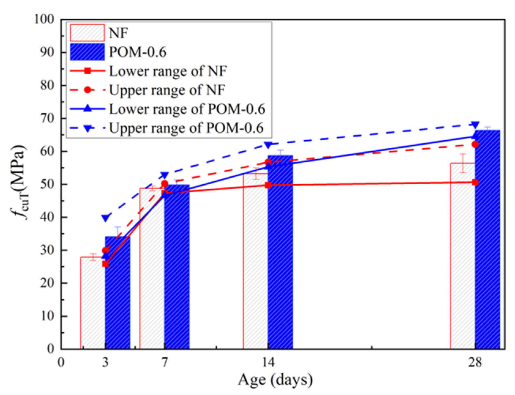
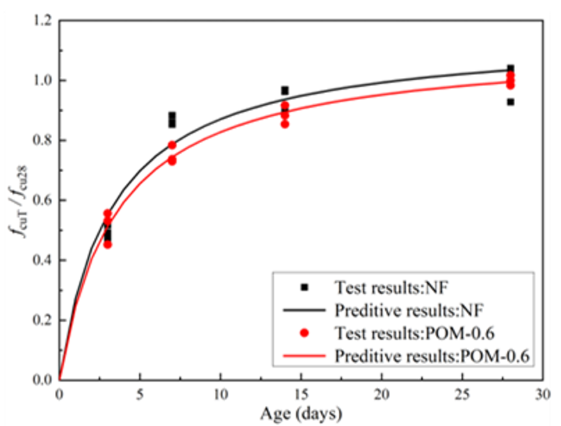
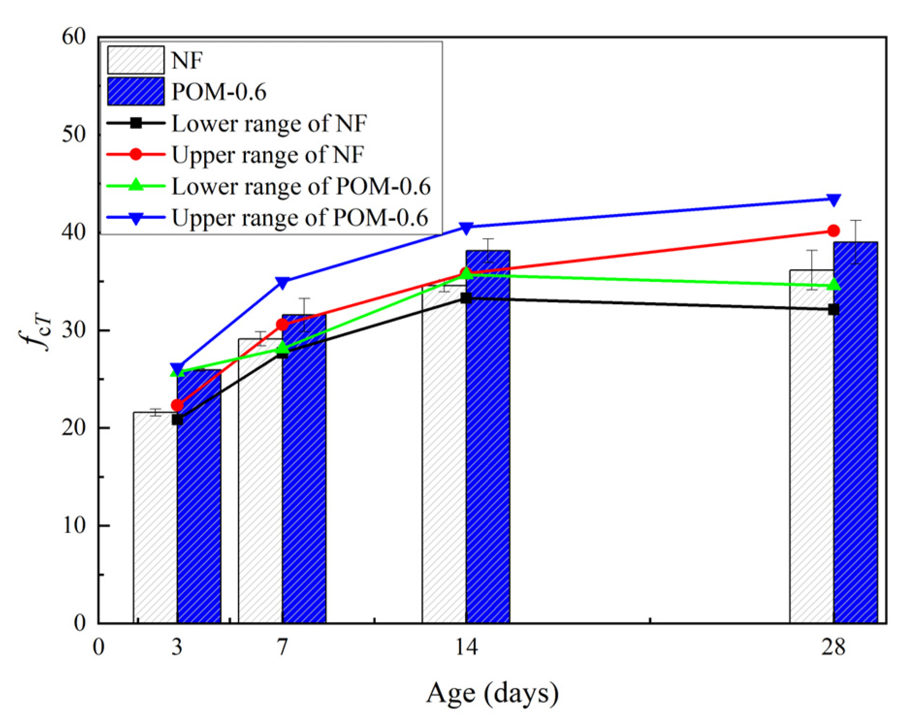
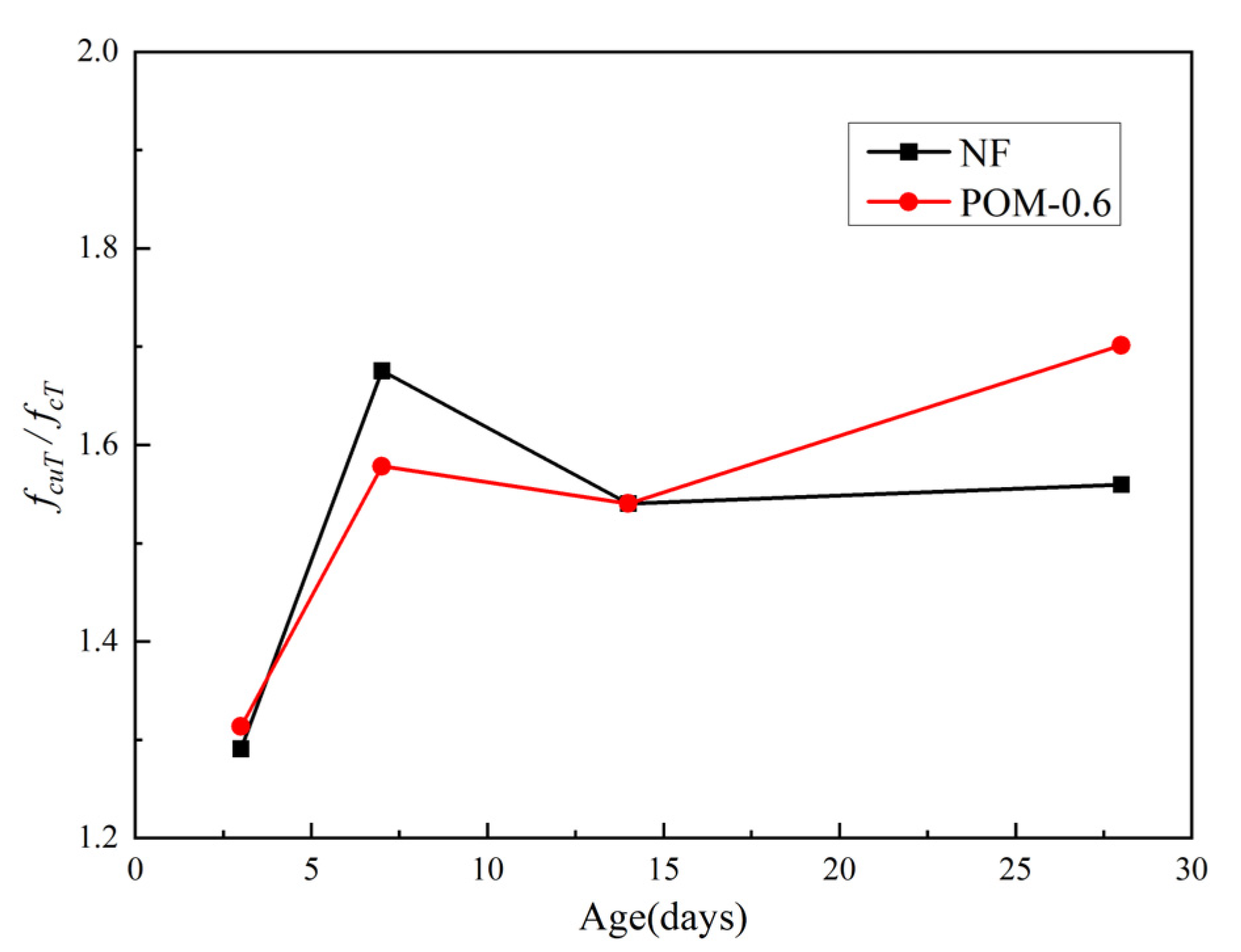
5.1. Cube Compressive Property
| NF | R2 = 0.98 | (6) | |
| POM0.6 | R2 = 0.99 | (7) |
5.2. Axial Compressive Property
| NF | R2 = 0.96 | (8) | |
| POM0.6 | R2 = 0.89 | (9) |
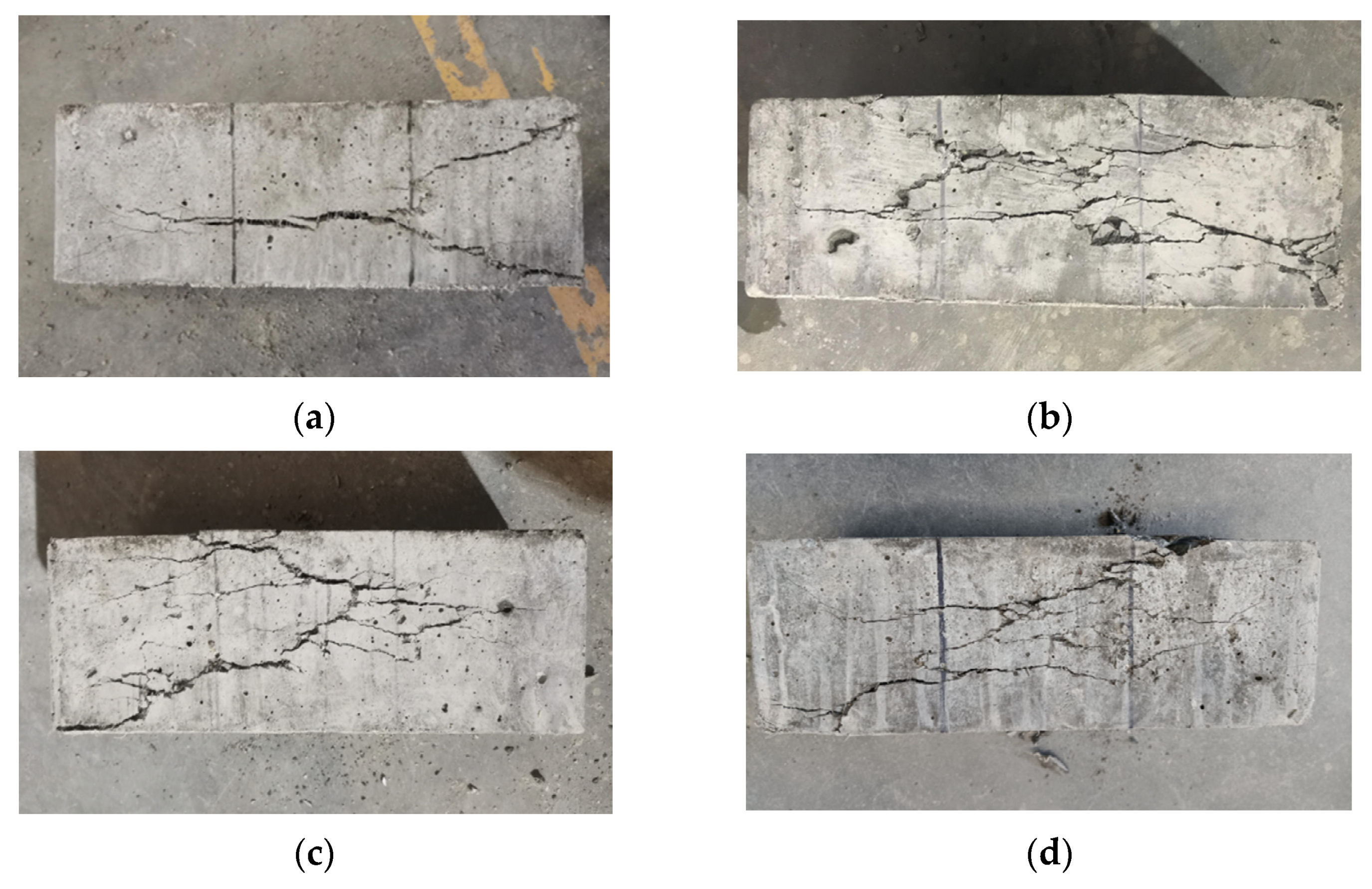
5.3. Splitting Tensile Property
| NF | R2 = 0.84 | (10) | |
| POM0.6 | R2 = 0.91 | (11) | |
| NF | R2 = 0.95 | (12) | |
| POM0.6 | R2 = 0.98 | (13) |
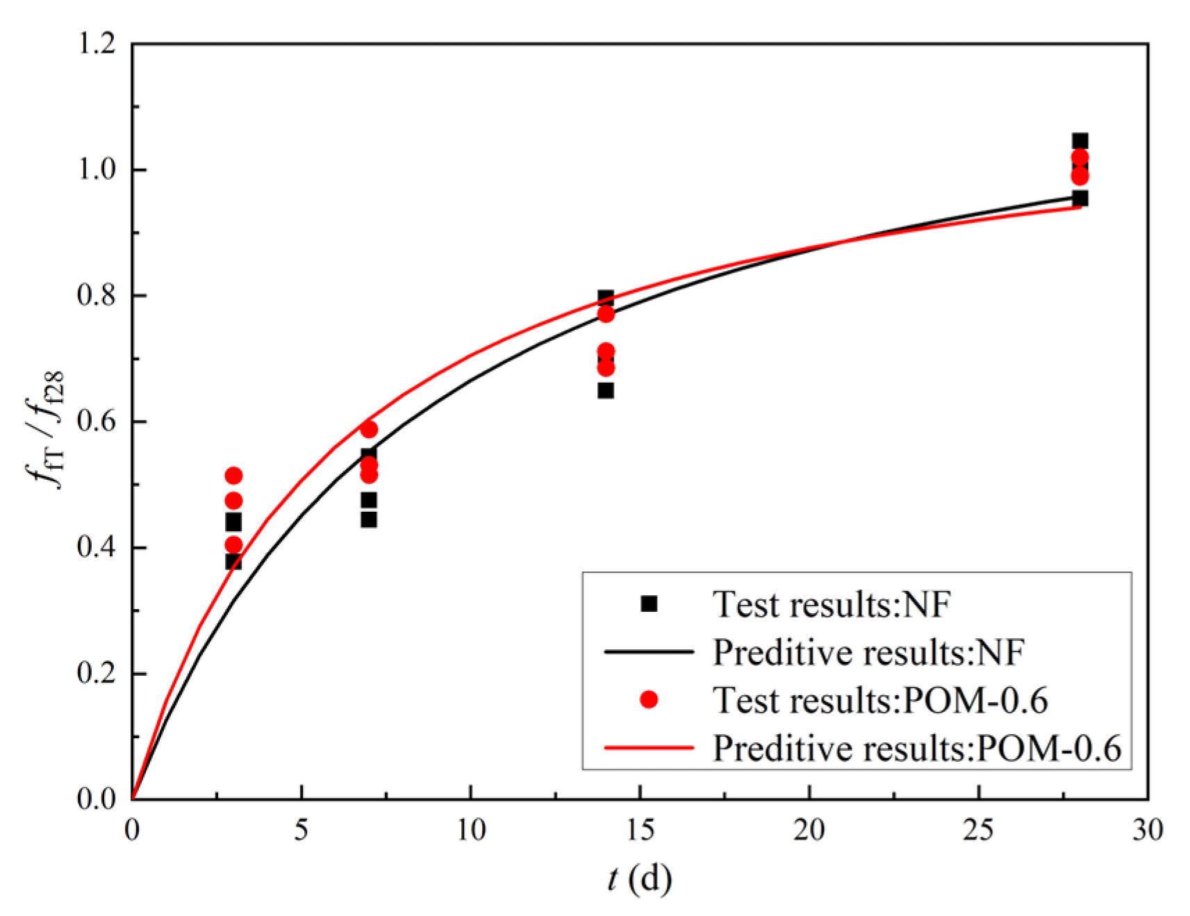
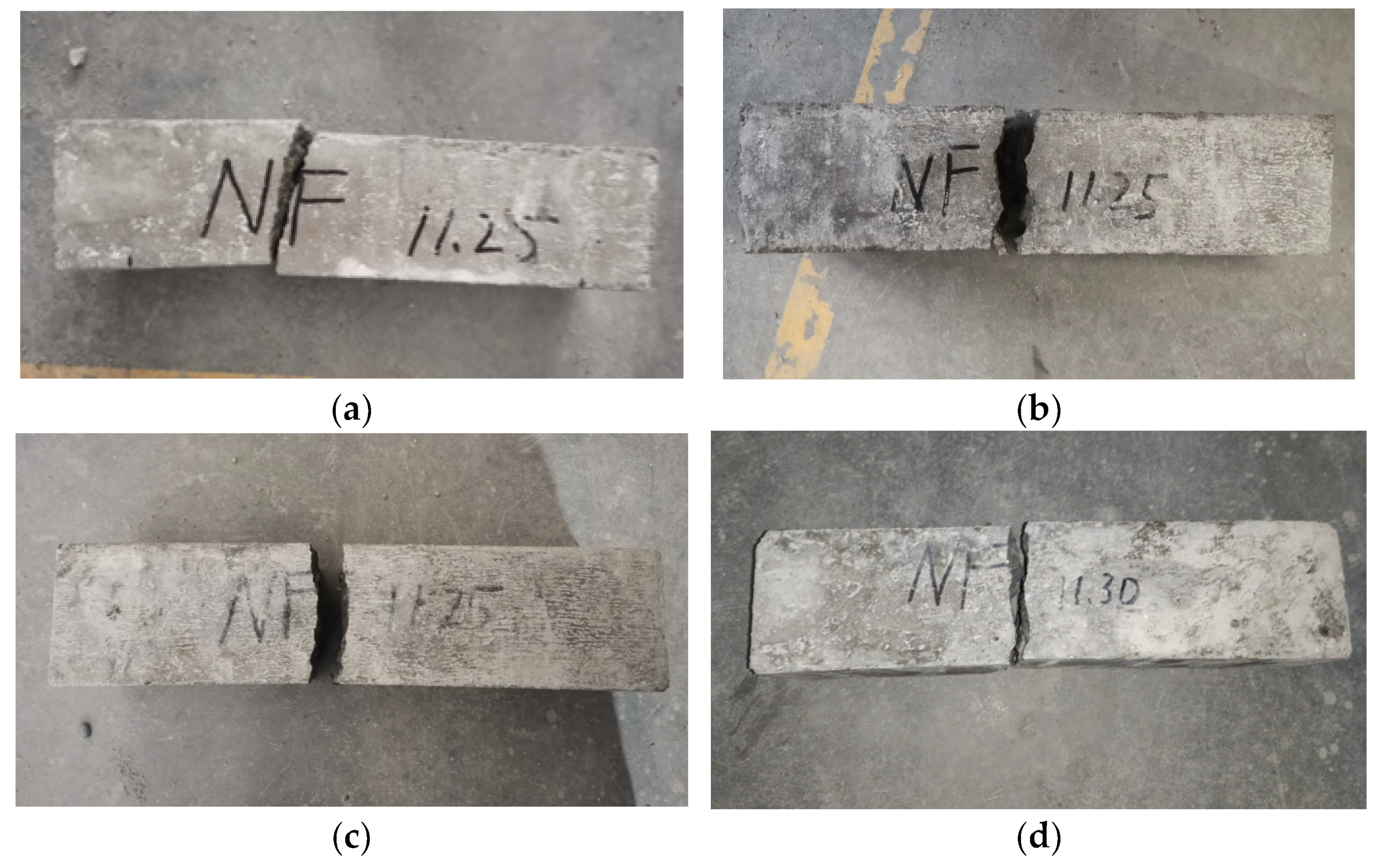
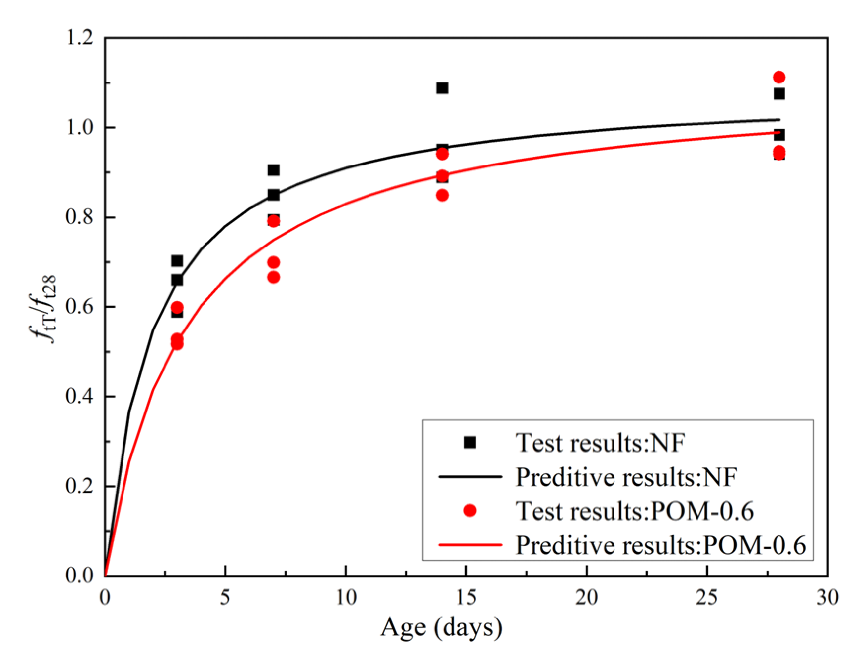
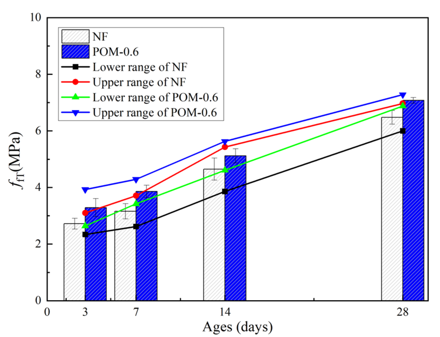
5.4. Flexural Property
| NF | R2 = 0.97 | (14) | |
| POM0.6 | R2 = 0.97 | (15) |
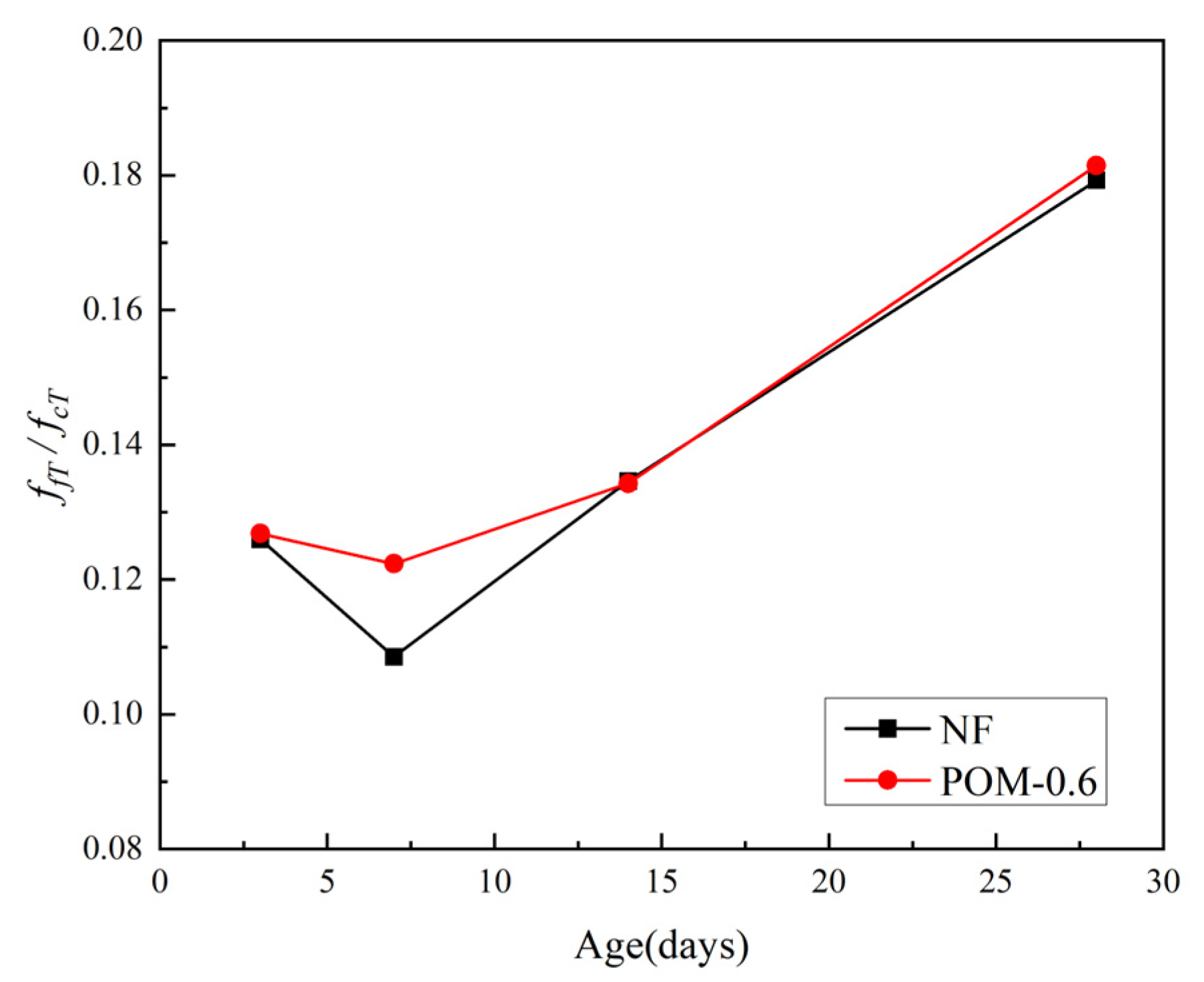
6. Discussion
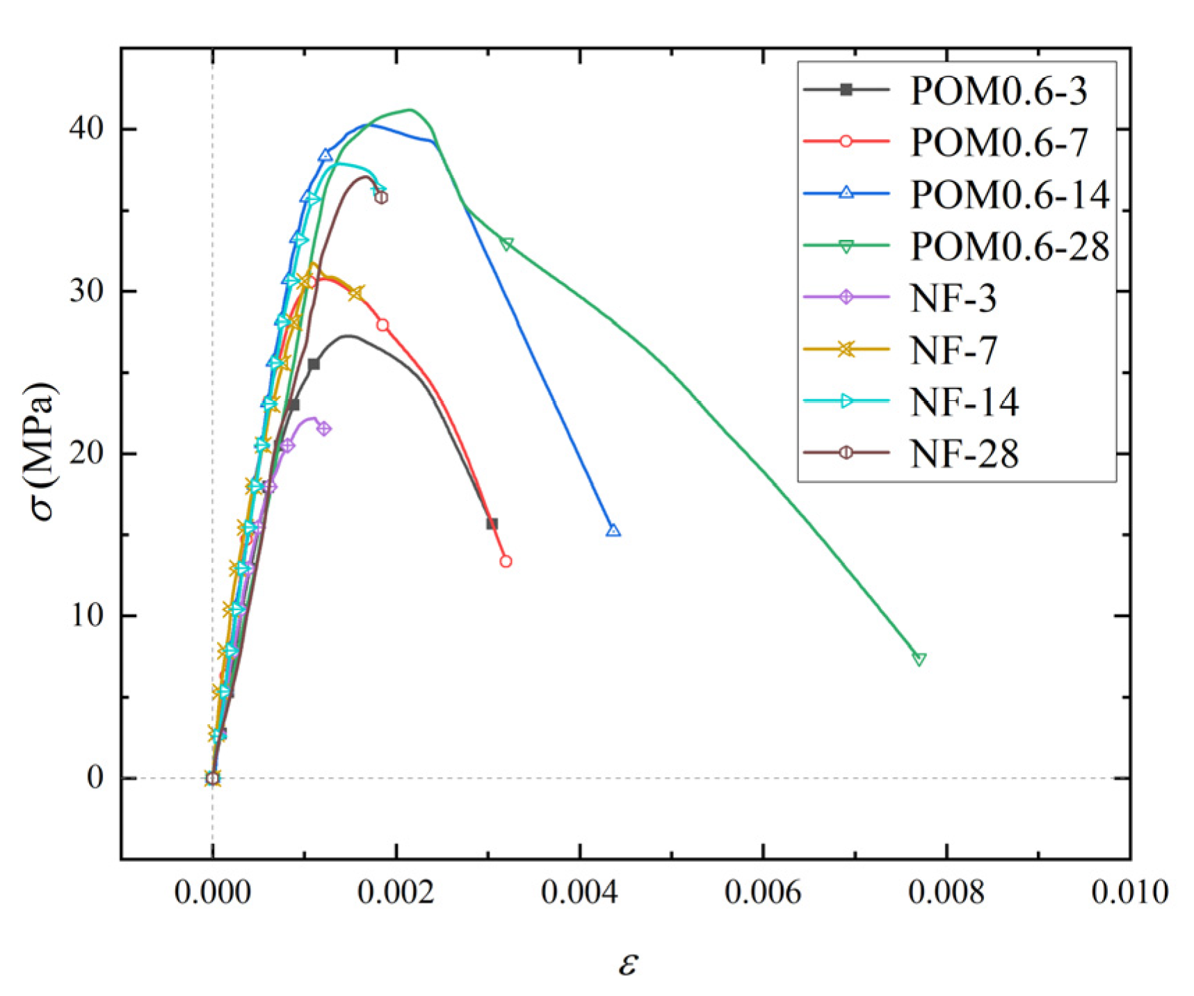
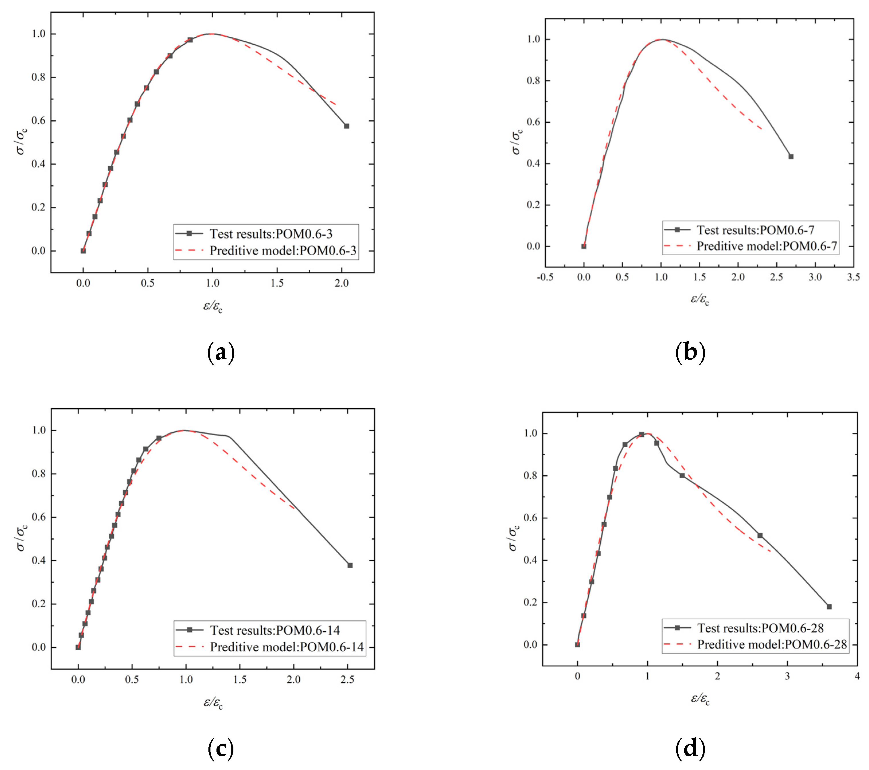
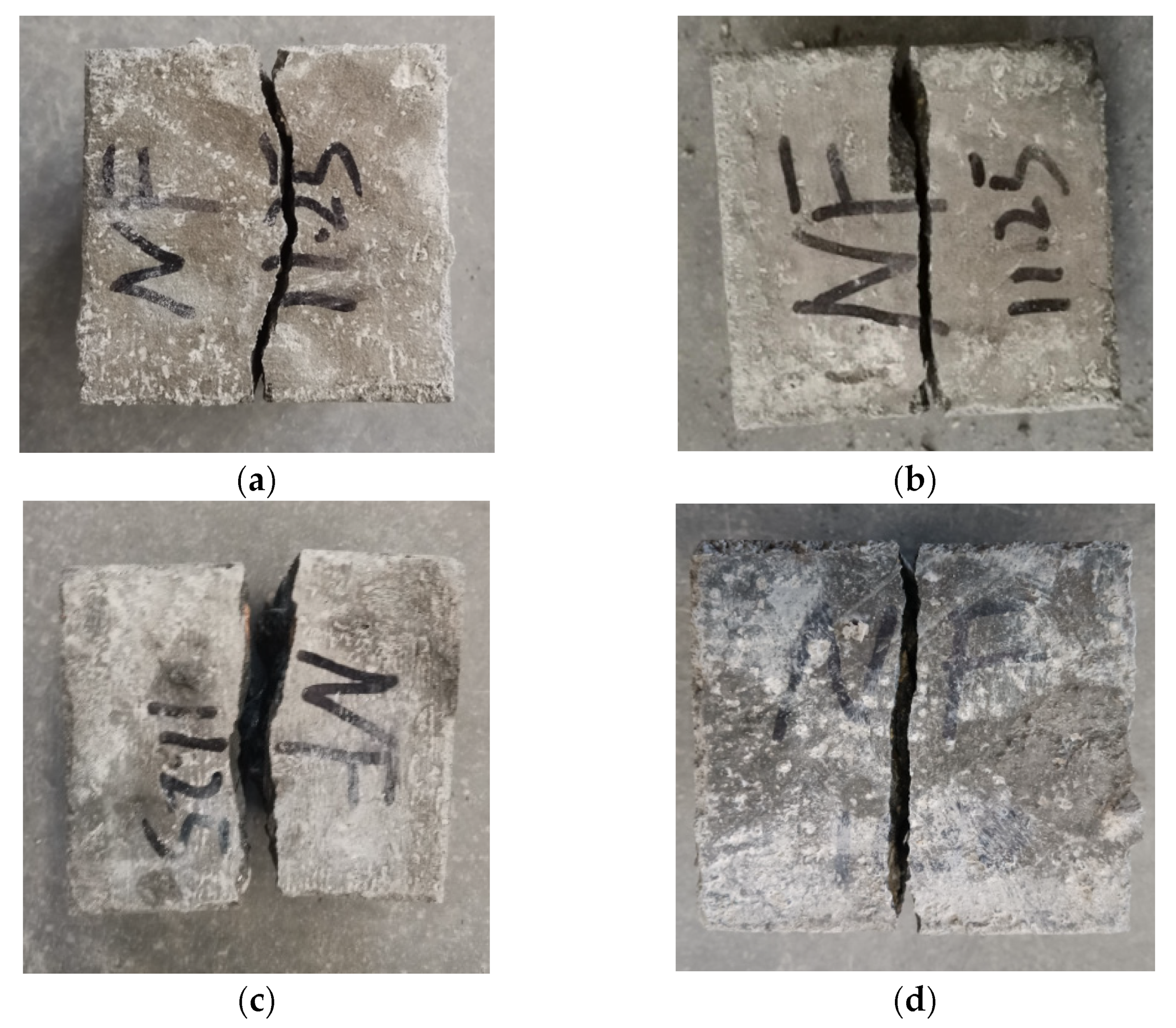
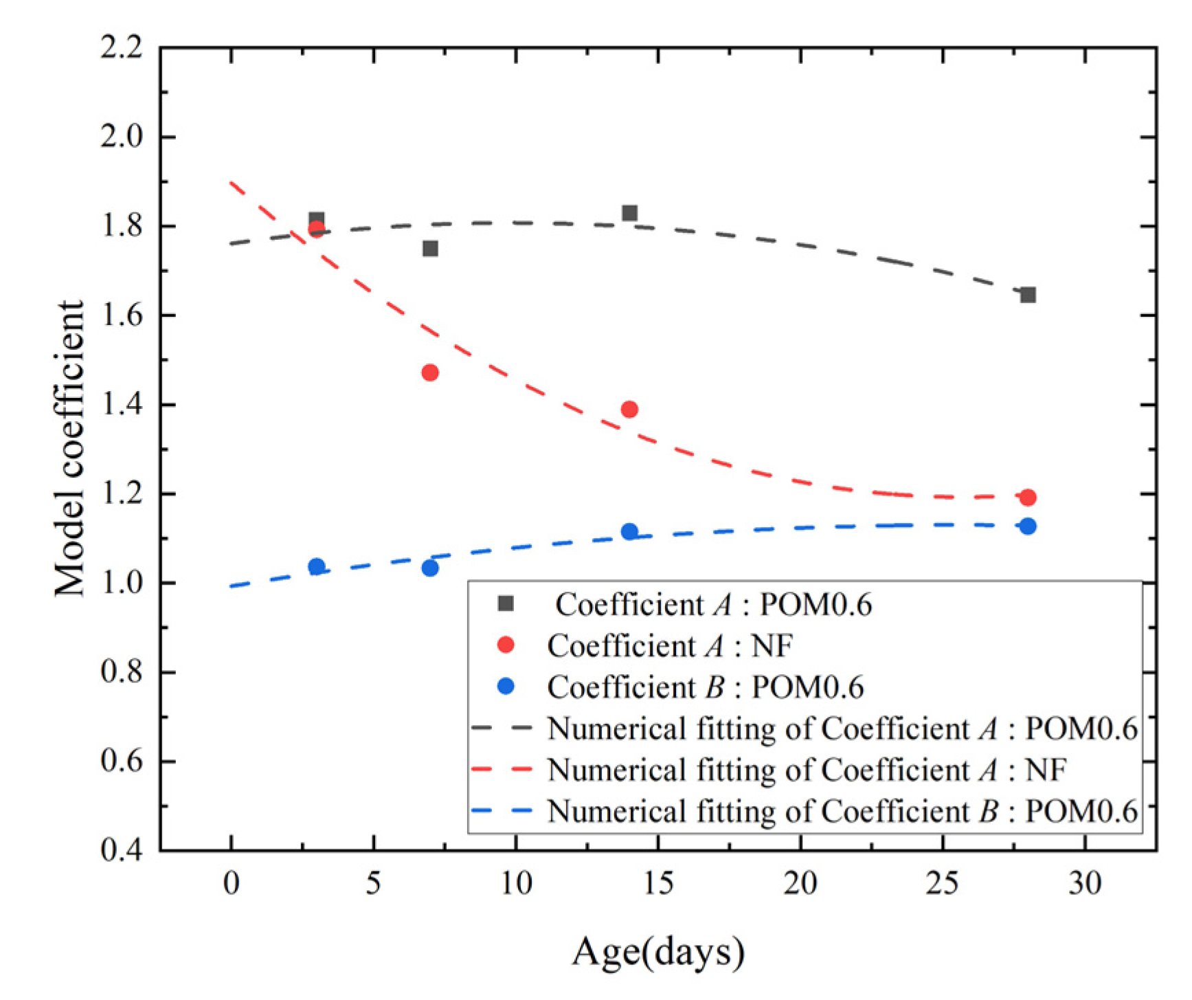
6.1. Stress–Strain Curve of SWSSC
| (16) | ||
| (17) | ||
| (18) | ||
| POM0.6 | (19) | |
| NF | (20) | |
| POM0.6 | (21) |
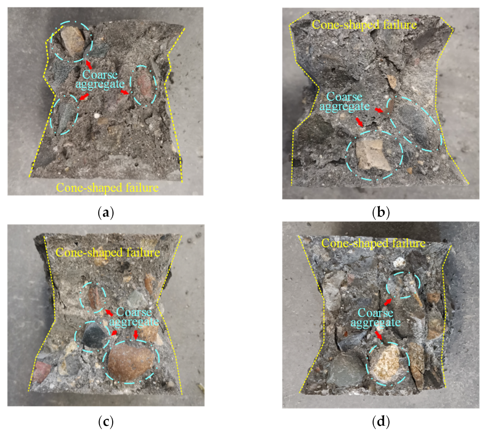
6.2. Microstructure
7. Conclusions
Author Contributions
Funding
Institutional Review Board Statement
Informed Consent Statement
Data Availability Statement
Acknowledgments
Conflicts of Interest
References
- Guo, M.; Hu, B.; Xing, F.; Zhou, X.; Sun, M.; Sui, L.; Zhou, Y. Characterization of the mechanical properties of eco-friendly concrete made with untreated sea sand and seawater based on statistical analysis. Constr. Build. Mater. 2020, 234, 117339. [Google Scholar] [CrossRef]
- Etxeberria, M.; Gonzalez-Corominas, A.; Pardo, P. Influence of seawater and blast furnace cement employment on recycled aggregate concretes’ properties. Constr. Build. Mater. 2016, 115, 496–505. [Google Scholar] [CrossRef]
- Limeira, J.; Etxeberria, M.; Agulló, L.; Molina, D. Mechanical and durability properties of concrete made with dredged marine sand. Constr. Build. Mater. 2011, 25, 4165–4174. [Google Scholar] [CrossRef]
- Shi, Z.; Shui, Z.; Li, Q.; Geng, H. Combined effect of metakaolin and sea water on performance and microstructures of concrete. Constr. Build. Mater. 2015, 74, 57–64. [Google Scholar] [CrossRef]
- Dong, Z.; Wu, G.; Zhao, X.L.; Zhu, H.; Shao, X. Behaviors of hybrid beams composed of seawater sea-sand concrete (SWSSC) and a prefabricated UHPC shell reinforced with FRP bars. Constr. Build. Mater. 2019, 213, 32–42. [Google Scholar] [CrossRef]
- Yang, S.; Yang, C.; Huang, M.; Liu, Y.; Jiang, J.; Fan, G. Study on bond performance between FRP bars and seawater coral aggregate concrete. Constr. Build. Mater. 2018, 173, 272–288. [Google Scholar] [CrossRef]
- Dong, Z.; Wu, G.; Xu, Y. Experimental study on the bond durability between steel-FRP composite bars (SFCBs) and sea sand concrete in ocean environment. Constr. Build. Mater. 2016, 115, 277–284. [Google Scholar] [CrossRef]
- Wang, J.; Yang, L.; Yang, J. Bond behavior of epoxy-coated reinforcing bars with seawater sea-sand concrete. ACI Struct. J. 2020, 117, 193–208. [Google Scholar] [CrossRef]
- Shi, Y.; Luo, Z.; Zhou, X.; Xue, X.; Li, J. Post-fire mechanical properties of titanium–clad bimetallic steel in different cooling approaches. J. Constr. Steel Res. 2022, 191, 107169. [Google Scholar] [CrossRef]
- Shi, Y.; Luo, Z.; Zhou, X.; Xue, X.; Xiang, Y. Post-fire performance of bonding interface in explosion-welded stainless-clad bimetallic steel. J. Constr. Steel Res. 2022, 193, 107285. [Google Scholar] [CrossRef]
- Hua, J.; Wang, F.; Xue, X.; Ding, Z.; Chen, Z. Residual monotonic mechanical properties of bimetallic steel bar with fatigue damage. J. Build. Eng. 2022, 55, 104703. [Google Scholar] [CrossRef]
- Hua, J.; Wang, F.; Xiang, Y.; Yang, Z.; Xue, X.; Huang, L.; Wang, N. Mechanical properties of stainless-clad bimetallic steel bars exposed to elevated temperatures. Fire Saf. J. 2022, 127, 103521. [Google Scholar] [CrossRef]
- Hua, J.; Wang, F.; Yang, Z.; Xue, X.; Huang, L.; Chen, Z. Low-cycle fatigue properties of bimetallic steel bars after exposure to elevated temperature. J. Constr. Steel Res. 2021, 187, 106959. [Google Scholar] [CrossRef]
- Hua, J.; Wang, F.; Xue, X.; Fan, H.; Yan, W. Fatigue properties of bimetallic steel bar: An experimental and numerical study. Eng. Fail. Anal. 2022, 136, 106212. [Google Scholar] [CrossRef]
- Hua, J.; Wang, F.; Xue, X. Study on fatigue properties of post-fire bimetallic steel bar with different cooling methods. Structures 2022, 40, 633–645. [Google Scholar] [CrossRef]
- Hua, J.; Fan, H.; Yan, W.; Wang, N.; Xue, X.; Huang, L. Seismic resistance of the corroded bimetallic steel bar under different strain amplitudes. Constr. Build. Mater. 2022, 319, 126088. [Google Scholar] [CrossRef]
- Hua, J.; Wang, F.; Wang, N.; Huang, L.; Hai, L.; Li, Y.; Zhu, X.; Xue, X. Experimental and numerical investigations on corroded stainless-clad bimetallic steel bar with artificial damage. J. Build. Eng. 2021, 44, 102779. [Google Scholar] [CrossRef]
- Hua, J.; Fan, H.; Xue, X.; Wang, F.; Chen, Z.; Huang, L.; Wang, N. Tensile and low-cycle fatigue performance of bimetallic steel bars with corrosion. J. Build. Eng. 2021, 43, 103188. [Google Scholar] [CrossRef]
- Xiao, J.; Qiang, C.; Nanni, A.; Zhang, K. Use of sea-sand and seawater in concrete construction: Current status and future opportunities. Constr. Build. Mater. 2017, 155, 1101–1111. [Google Scholar] [CrossRef]
- Liu, G.; Hua, J.; Wang, N.; Deng, W.; Xue, X. Material Alternatives for Concrete Structures on Remote Islands: Based on Life-cycle cost Analysis. Adv. Civ. Eng. 2022, 2022, 7329408. [Google Scholar] [CrossRef]
- Zhang, H.; Zhang, W.; Meng, Y.; Li, H. Deterioration of sea sand roller compacted concrete used in island reef airport runway under salt spray. Constr. Build. Mater. 2022, 322, 126523. [Google Scholar] [CrossRef]
- Zhou, J.; He, X.; Zhang, L. CT characteristic analysis of sea-sand concrete exposed in simulated marine environment. Constr. Build. Mater. 2021, 268, 121170. [Google Scholar] [CrossRef]
- Dhondy, T.; Remennikov, A.; Shiekh, M.N. Benefits of using sea sand and seawater in concrete: A comprehensive review. Aust. J. Struct. Eng. 2019, 20, 280–289. [Google Scholar] [CrossRef]
- Li, P.; Li, W.; Yu, T.; Qu, F.; Tam, V.W.Y. Investigation on early-age hydration, mechanical properties and microstructure of seawater sea sand cement mortar. Constr. Build. Mater. 2020, 249, 118776. [Google Scholar] [CrossRef]
- Li, Y.-L.; Zhao, X.-L.; Singh Raman, R.K.; Al-Saadi, S. Thermal and mechanical properties of alkali-activated slag paste, mortar and concrete utilising seawater and sea sand. Constr. Build. Mater. 2018, 159, 704–724. [Google Scholar] [CrossRef]
- Xiao, J.; Zhang, Q.; Zhang, P.; Shen, L.; Qiang, C. Mechanical behavior of concrete using seawater and sea-sand with recycled coarse aggregates. Struct. Concr. 2019, 20, 1631–1643. [Google Scholar] [CrossRef]
- Younis, A.; Ebead, U.; Suraneni, P.; Nanni, A. Fresh and hardened properties of seawater-mixed concrete. Constr. Build. Mater. 2018, 190, 276–286. [Google Scholar] [CrossRef]
- Shah, S.F.A.; Chen, B.; Oderji, S.Y.; Aminul Haque, M.; Ahmad, M.R. Comparative study on the effect of fiber type and content on the performance of one-part alkali-activated mortar. Constr. Build. Mater. 2020, 243, 118221. [Google Scholar] [CrossRef]
- Zhou, X.; Zeng, Y.; Chen, P.; Jiao, Z.; Zheng, W. Mechanical properties of basalt and polypropylene fibre-reinforced alkali-activated slag concrete. Constr. Build. Mater. 2020, 269, 121284. [Google Scholar] [CrossRef]
- Yu, K.; Ding, Y.; Liu, J.; Bai, Y. Energy dissipation characteristics of all-grade polyethylene fiber-reinforced engineered cementitious composites (PE-ECC). Cem. Concr. Compos. 2020, 106, 103459. [Google Scholar] [CrossRef]
- Shan, W.; Liu, J.; Ding, Y.; Mao, W.; Jiao, Y. Assessment of bond-slip behavior of hybrid fiber reinforced engineered cementitious composites (ECC) and deformed rebar via AE monitoring. Cem. Concr. Compos. 2021, 118, 103961. [Google Scholar] [CrossRef]
- GB/T 50081-2002; Standard for Test Method of Mechanical Properties on Ordinary Concrete. Ministry of Construction of the PR China: Beijing, China, 2002.
- Das, S.; Habibur Rahman Sobuz, M.; Tam, V.W.Y.; Akid, A.S.M.; Sutan, N.M.; Rahman, F.M.M. Effects of incorporating hybrid fibres on rheological and mechanical properties of fibre reinforced concrete. Constr. Build. Mater. 2020, 262, 120561. [Google Scholar] [CrossRef]
- Wu, H.; Lin, X.; Zhou, A. A review of mechanical properties of fibre reinforced concrete at elevated temperatures. Cem. Concr. Res. 2020, 135, 106117. [Google Scholar] [CrossRef]
- JGJ 52-2006; Standard for Technical Requirements and Test Method of Sand and Crushed Stone (or Gravel) for Ordinary Concrete. China Construction Industry Press: Beijing, China, 2006.
- Vafaei, D.; Ma, X.; Hassanli, R.; Duan, J.; Zhuge, Y. Microstructural behaviour and shrinkage properties of high-strength fiber-reinforced seawater sea-sand concrete. Constr. Build. Mater. 2022, 320, 126222. [Google Scholar] [CrossRef]
- Abbadi, A.; Basheer, P.A.M.; Forth, J.P. Effect of hybrid fibres on the static load performance of concrete beams. Mater. Today Proc. 2022, 65, 681–687. [Google Scholar] [CrossRef]


| Type | Tensile Strength (MPa) | Elongation (%) | Melting Point (°C) | Elastic Modulus (GPa) | Density (kg/m3) |
|---|---|---|---|---|---|
| POM | 967 | 18 | 165 | 8 | 1400 |
| Steel | 200~2760 | 0.5~35 | 1370 | 200 | 7800 |
| Glass | 1034~3792 | 1.5~3.5 | 860 | 72 | 2500~2700 |
| Carbon | 1550~6960 | 2.5~3.2 | 3000 | 159~965 | 1800 |
| Basalt | 3200 | 3.1 | 1200 | 89 | 2700 |
| PP | 400 | 30 | 180 | 3.85 | 910 |
| Cl− | SO42− | Na+ | K+ | Mg2+ | Ca2+ | Total | |
|---|---|---|---|---|---|---|---|
| Fresh water (mg/L) | 12.3 | 36.8 | 8.7 | 2.8 | 9.6 | 53.1 | 123.3 |
| Seawater (mg/L) | 19,365.5 | 2537.5 | 11,208.7 | 389.9 | 1321.7 | 395.8 | 35,219.1 |
| Sea–sand (mg/kg) | 7.4 | 34.9 | 14.2 | 4.0 | 3.0 | 13.8 | 77.3 |
| Types | Cement (kg/m3) | Fly Ash (kg/m3) | Mineral Powder (kg/m3) | Sea–Sand (kg/m3) | Coarse Aggregate (kg/m3) | Seawater (kg/m3) | POM Fiber (kg/m3) | W/C Ratio |
|---|---|---|---|---|---|---|---|---|
| NF | 264 | 88 | 88 | 831 | 1016 | 160 | 0 | 0.36 |
| POM0.6 | 8.4 |
| Types | Slump (mm) | Expansibility 1 (mm) | Expansibility 2 (mm) | Expansibility (mm) |
|---|---|---|---|---|
| NF | 175 | 291 | 286 | 290 |
| POM0.6 | 130 | 235 | 222 | 230 |
| C20 SSRCA [26] | 60 | - | - | - |
| C30 SSRCA [26] | 35 | - | - | - |
| C40 SSRCA [26] | 210 | - | - | - |
| C50 SSRCA [26] | 200 | - | - | - |
| Number | fcuT (MPa) | fcuT-mean (MPa) | Standard Deviation | COV | 95% Confidence Interval | |
|---|---|---|---|---|---|---|
| Lower Range | Upper Range | |||||
| NF-3-1 | 29.16 | |||||
| NF-3-2 | 27.74 | 27.87 | 1.00 | 0.0359 | 25.87 | 29.87 |
| NF-3-3 | 26.72 | |||||
| POM0.6-3-1 | 35.25 | |||||
| POM0.6-3-2 | 36.93 | 34.08 | 2.93 | 0.0859 | 28.22 | 39.93 |
| POM0.6-3-3 | 30.05 | |||||
| NF-7-1 | 48.45 | |||||
| NF-7-2 | 48.13 | 48.79 | 0.72 | 0.0148 | 47.35 | 50.24 |
| NF-7-3 | 49.80 | |||||
| POM0.6-7-1 | 52.03 | |||||
| POM0.6-7-2 | 48.45 | 49.79 | 1.59 | 0.0320 | 46.61 | 52.98 |
| POM0.6-3-3 | 48.9 | |||||
| NF-14-1 | 54.62 | |||||
| NF-14-2 | 54.27 | 53.22 | 1.74 | 0.0328 | 49.73 | 56.70 |
| NF-14-3 | 50.76 | |||||
| POM0.6-14-1 | 56.69 | |||||
| POM0.6-14-2 | 60.87 | 58.73 | 1.71 | 0.0291 | 55.31 | 62.15 |
| POM0.6-14-3 | 58.63 | |||||
| NF-28-1 | 58.67 | |||||
| NF-28-2 | 58.15 | 56.38 | 2.87 | 0.0510 | 50.64 | 62.13 |
| NF-28-3 | 52.33 | |||||
| POM0.6-28-1 | 65.29 | |||||
| POM0.6-28-2 | 66.36 | 66.39 | 0.91 | 0.0138 | 64.56 | 68.22 |
| POM0.6-28-3 | 67.53 | |||||
| Number | fcT (MPa) | fcT-mean (MPa) | Standard Deviation | COV | 95% Confidence Interval | |
|---|---|---|---|---|---|---|
| Lower Range | Upper Range | |||||
| NF-3-1 | 21.09 | |||||
| NF-3-2 | 21.94 | 21.59 | 0.36 | 0.0169 | 20.86 | 22.32 |
| NF-3-3 | 21.75 | |||||
| POM0.6-3-1 | 25.91 | |||||
| POM0.6-3-2 | 25.82 | 25.94 | 0.12 | 0.0045 | 25.71 | 26.18 |
| POM0.6-3-3 | 26.10 | |||||
| NF-7-1 | 30.13 | |||||
| NF-7-2 | 28.50 | 29.12 | 0.72 | 0.0247 | 27.69 | 30.56 |
| NF-7-3 | 28.74 | |||||
| POM0.6-7-1 | 33.14 | |||||
| POM0.6-7-2 | 29.17 | 31.55 | 1.71 | 0.0543 | 28.12 | 34.97 |
| POM0.6-3-3 | 32.33 | |||||
| NF-14-1 | 33.74 | |||||
| NF-14-2 | 34.63 | 34.55 | 0.63 | 0.0183 | 33.29 | 35.81 |
| NF-14-3 | 35.28 | |||||
| POM0.6-14-1 | 36.58 | |||||
| POM0.6-14-2 | 39.56 | 38.13 | 1.22 | 0.0320 | 35.69 | 40.57 |
| POM0.6-14-3 | 38.25 | |||||
| NF-28-1 | 34.94 | |||||
| NF-28-2 | 34.53 | 36.15 | 2.01 | 0.0555 | 32.13 | 40.17 |
| NF-28-3 | 38.98 | |||||
| POM0.6-28-1 | 39.41 | |||||
| POM0.6-28-2 | 41.52 | 39.02 | 2.22 | 0.0568 | 34.58 | 43.46 |
| POM0.6-28-3 | 36.13 | |||||
| Number | ftT (MPa) | ftT-mean (MPa) | Standard Deviation | COV | 95% Confidence Interval | |
|---|---|---|---|---|---|---|
| Lower Range | Upper Range | |||||
| NF-3-1 | 2.60 | |||||
| NF-3-2 | 2.77 | 1.99 | 0.14 | 0.0726 | 1.70 | 2.28 |
| NF-3-3 | 2.43 | |||||
| POM0.6-3-1 | 2.45 | |||||
| POM0.6-3-2 | 2.57 | 2.01 | 0.13 | 0.0661 | 1.75 | 2.28 |
| POM0.6-3-3 | 2.91 | |||||
| NF-7-1 | 2.60 | |||||
| NF-7-2 | 2.77 | 2.60 | 0.14 | 0.0534 | 2.32 | 2.88 |
| NF-7-3 | 2.43 | |||||
| POM0.6-7-1 | 2.45 | |||||
| POM0.6-7-2 | 2.57 | 2.64 | 0.19 | 0.0737 | 2.25 | 3.03 |
| POM0.6-3-3 | 2.91 | |||||
| NF-14-1 | 2.91 | |||||
| NF-14-2 | 2.72 | 2.99 | 0.25 | 0.0853 | 2.48 | 3.50 |
| NF-14-3 | 3.33 | |||||
| POM0.6-14-1 | 4.09 | |||||
| POM0.6-14-2 | 3.48 | 3.29 | 0.14 | 0.0423 | 3.01 | 3.56 |
| POM0.6-14-3 | 3.46 | |||||
| NF-28-1 | 3.01 | |||||
| NF-28-2 | 3.29 | 3.06 | 0.17 | 0.0559 | 2.72 | 3.40 |
| NF-28-3 | 2.88 | |||||
| POM0.6-28-1 | 4.09 | |||||
| POM0.6-28-2 | 3.48 | 3.68 | 0.29 | 0.0795 | 3.09 | 4.26 |
| POM0.6-28-3 | 3.46 | |||||
| Number | ffT (MPa) | ffT-mean (MPa) | Standard Deviation | COV | 95% Confidence Interval | |
|---|---|---|---|---|---|---|
| Lower Range | Upper Range | |||||
| NF-3-1 | 2.84 | |||||
| NF-3-2 | 2.87 | 2.72 | 0.19 | 0.0703 | 2.34 | 3.10 |
| NF-3-3 | 2.45 | |||||
| POM0.6-3-1 | 3.36 | |||||
| POM0.6-3-2 | 3.64 | 3.29 | 0.32 | 0.0982 | 2.64 | 3.93 |
| POM0.6-3-3 | 2.86 | |||||
| NF-7-1 | 3.08 | |||||
| NF-7-2 | 2.88 | 3.16 | 0.27 | 0.0859 | 2.62 | 3.71 |
| NF-7-3 | 3.53 | |||||
| POM0.6-7-1 | 3.65 | |||||
| POM0.6-7-2 | 4.16 | 3.86 | 0.22 | 0.0568 | 3.42 | 4.29 |
| POM0.6-3-3 | 3.76 | |||||
| NF-14-1 | 5.16 | |||||
| NF-14-2 | 4.57 | 4.65 | 0.39 | 0.0843 | 3.86 | 5.43 |
| NF-14-3 | 4.21 | |||||
| POM0.6-14-1 | 4.85 | |||||
| POM0.6-14-2 | 5.46 | 5.12 | 0.25 | 0.0498 | 4.61 | 5.63 |
| POM0.6-14-3 | 5.04 | |||||
| NF-28-1 | 6.78 | |||||
| NF-28-2 | 6.19 | 6.48 | 0.24 | 0.0372 | 6.00 | 6.97 |
| NF-28-3 | 6.48 | |||||
| POM0.6-28-1 | 7.22 | |||||
| POM0.6-28-2 | 7.02 | 7.08 | 0.10 | 0.0140 | 6.88 | 7.28 |
| POM0.6-28-3 | 7.00 | |||||
Publisher’s Note: MDPI stays neutral with regard to jurisdictional claims in published maps and institutional affiliations. |
© 2022 by the authors. Licensee MDPI, Basel, Switzerland. This article is an open access article distributed under the terms and conditions of the Creative Commons Attribution (CC BY) license (https://creativecommons.org/licenses/by/4.0/).
Share and Cite
Wang, F.; Hua, J.; Xue, X.; Wang, N.; Yao, Y. Effects of Polyoxymethylene Fiber on Mechanical Properties of Seawater Sea-Sand Concrete with Different Ages. Polymers 2022, 14, 3472. https://doi.org/10.3390/polym14173472
Wang F, Hua J, Xue X, Wang N, Yao Y. Effects of Polyoxymethylene Fiber on Mechanical Properties of Seawater Sea-Sand Concrete with Different Ages. Polymers. 2022; 14(17):3472. https://doi.org/10.3390/polym14173472
Chicago/Turabian StyleWang, Fei, Jianmin Hua, Xuanyi Xue, Neng Wang, and Yunhang Yao. 2022. "Effects of Polyoxymethylene Fiber on Mechanical Properties of Seawater Sea-Sand Concrete with Different Ages" Polymers 14, no. 17: 3472. https://doi.org/10.3390/polym14173472
APA StyleWang, F., Hua, J., Xue, X., Wang, N., & Yao, Y. (2022). Effects of Polyoxymethylene Fiber on Mechanical Properties of Seawater Sea-Sand Concrete with Different Ages. Polymers, 14(17), 3472. https://doi.org/10.3390/polym14173472