
Continuously Reinforced Polymeric Composite for Additive Manufacturing—Development and Efficiency Analysis


Abstract
:
1. Introduction
1.1. Research Rationale
1.2. Continuous Reinforcement and Recycling PLA for AM
2. Experimental Program
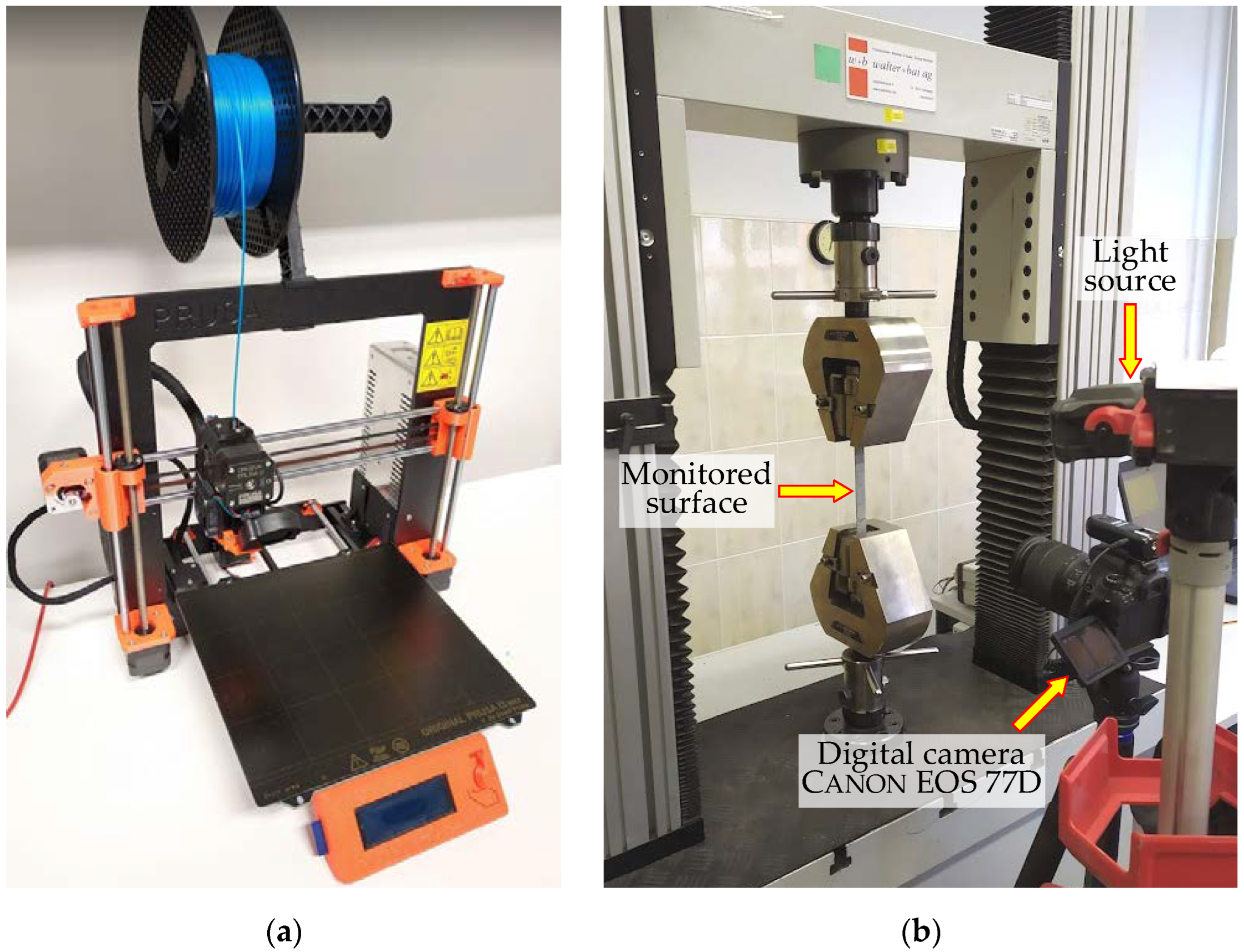
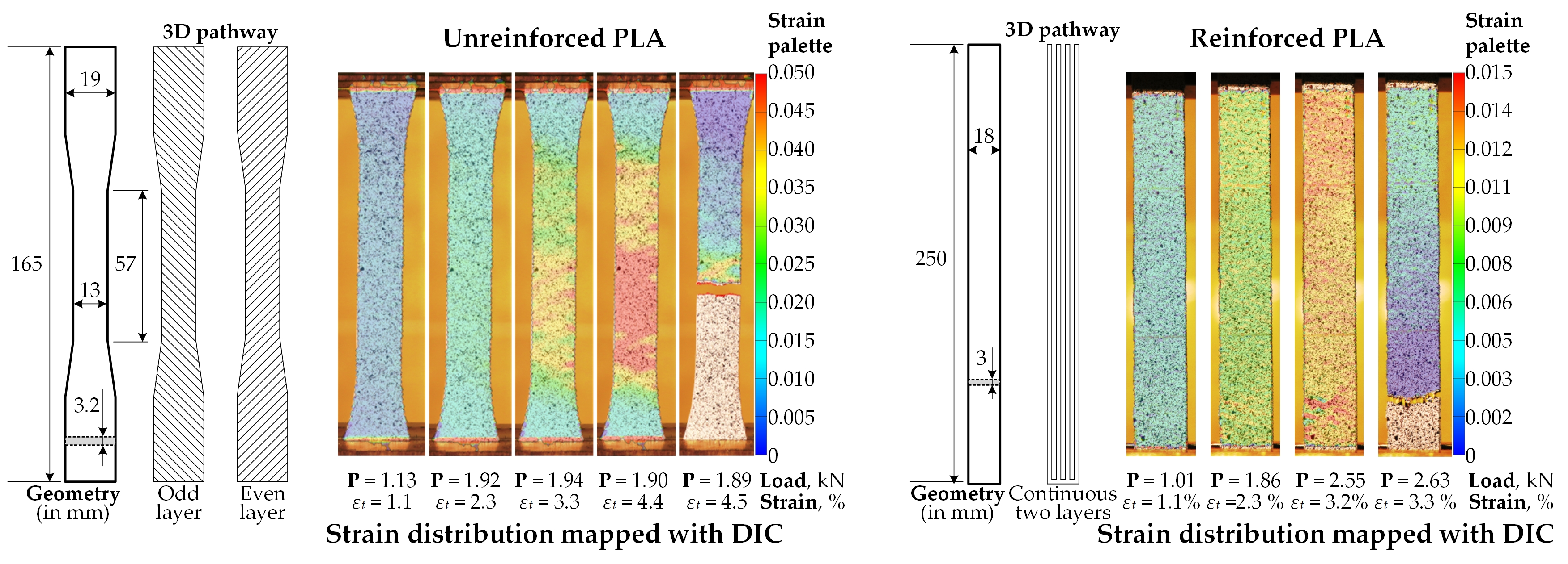
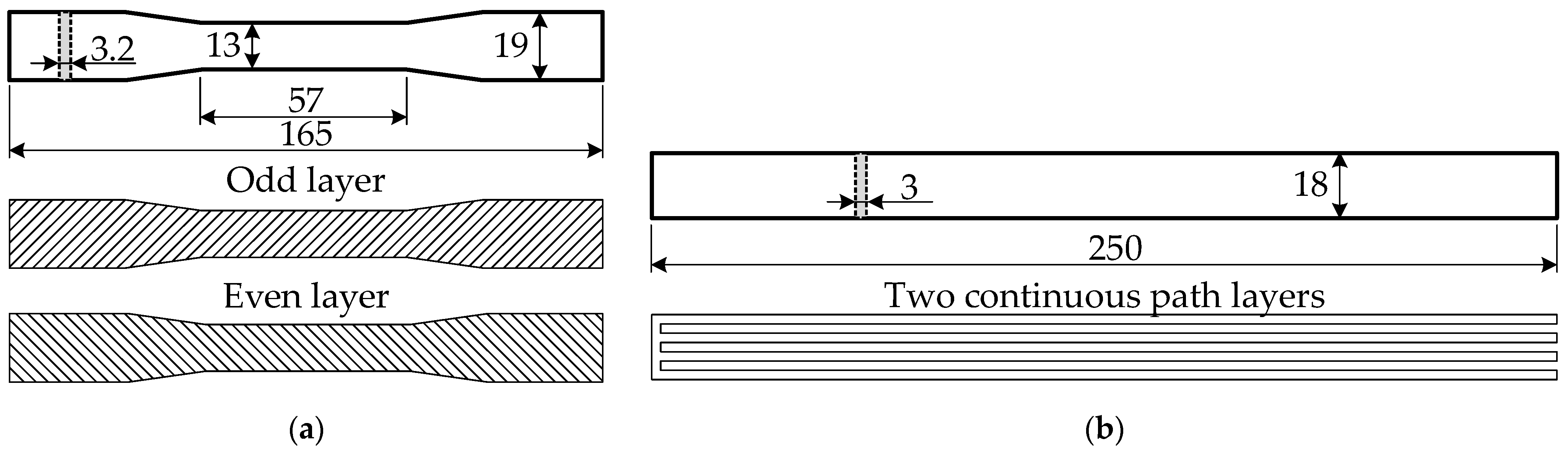
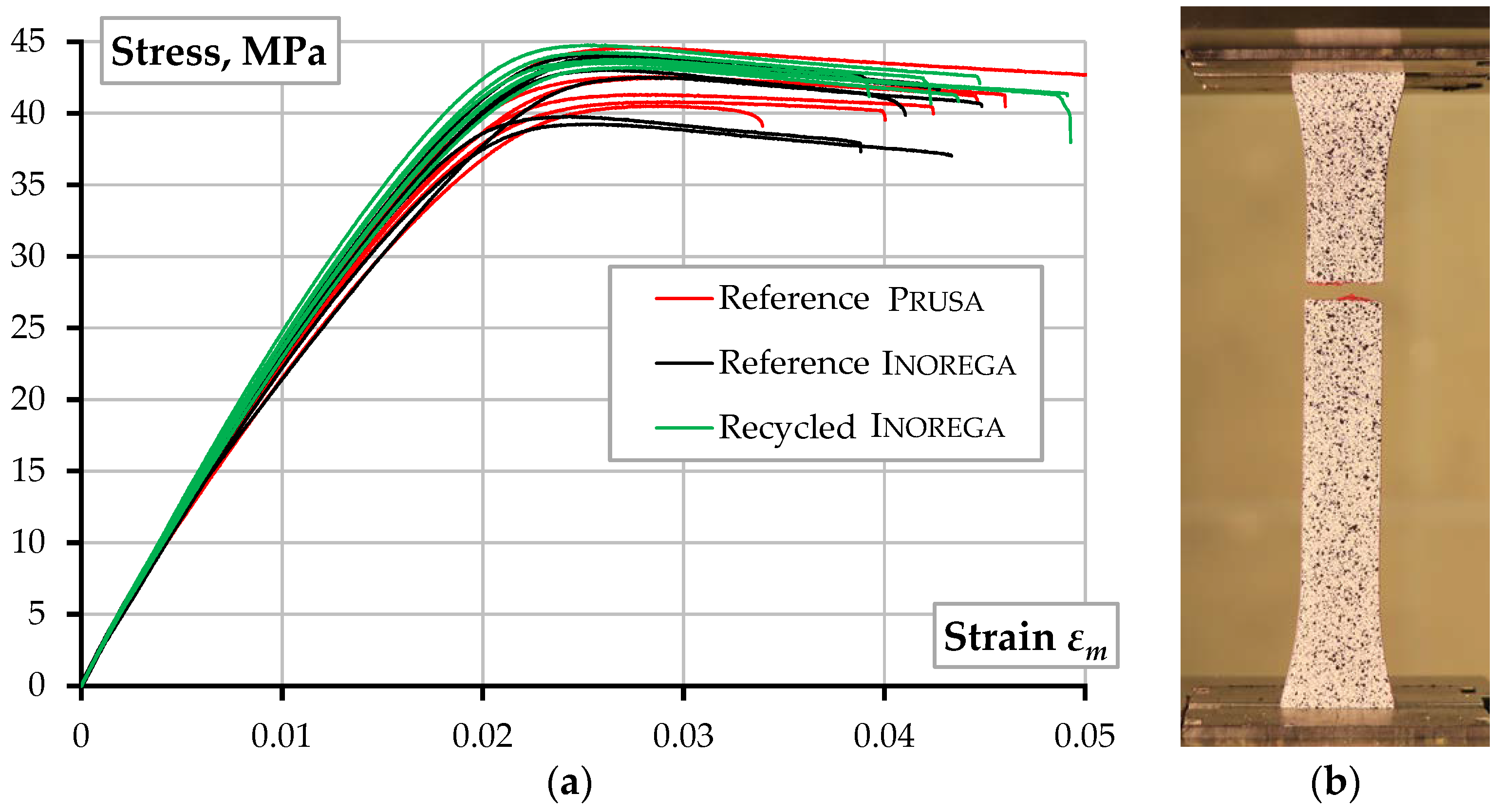
2.1. Tensile Tests of the Printed Polymers
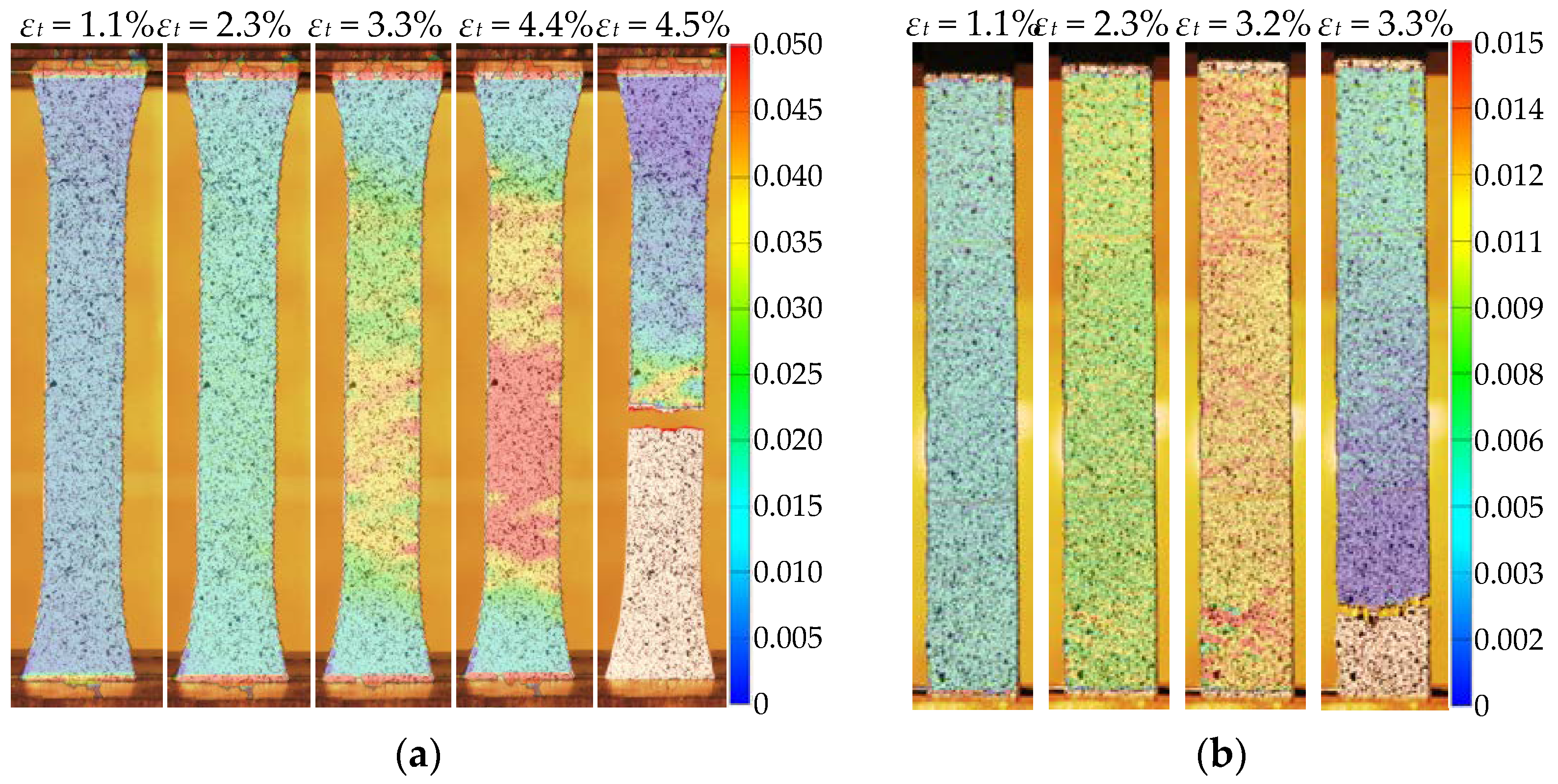
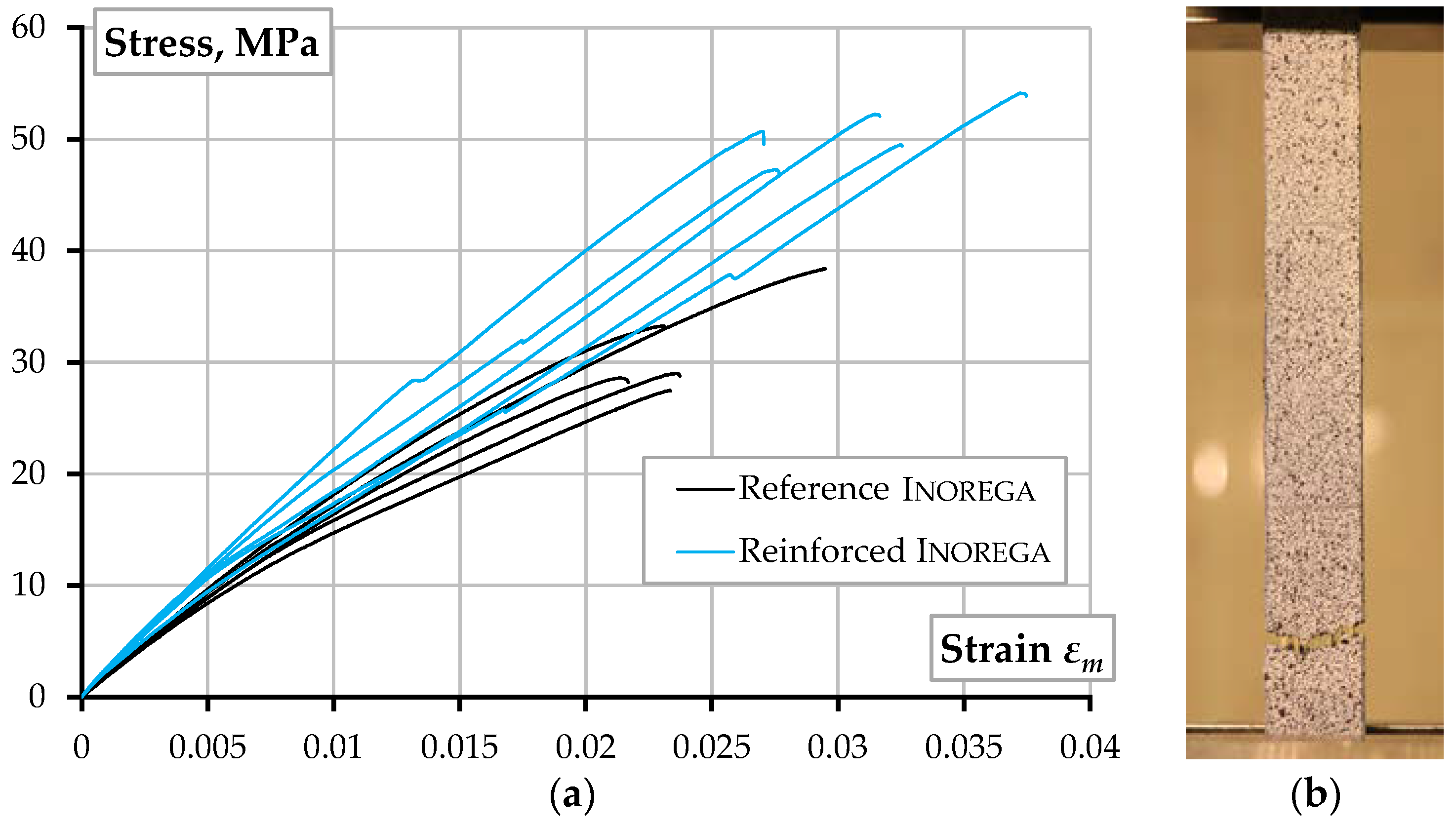
2.2. Tensile Tests of Reinforced PLA
3. Discussion
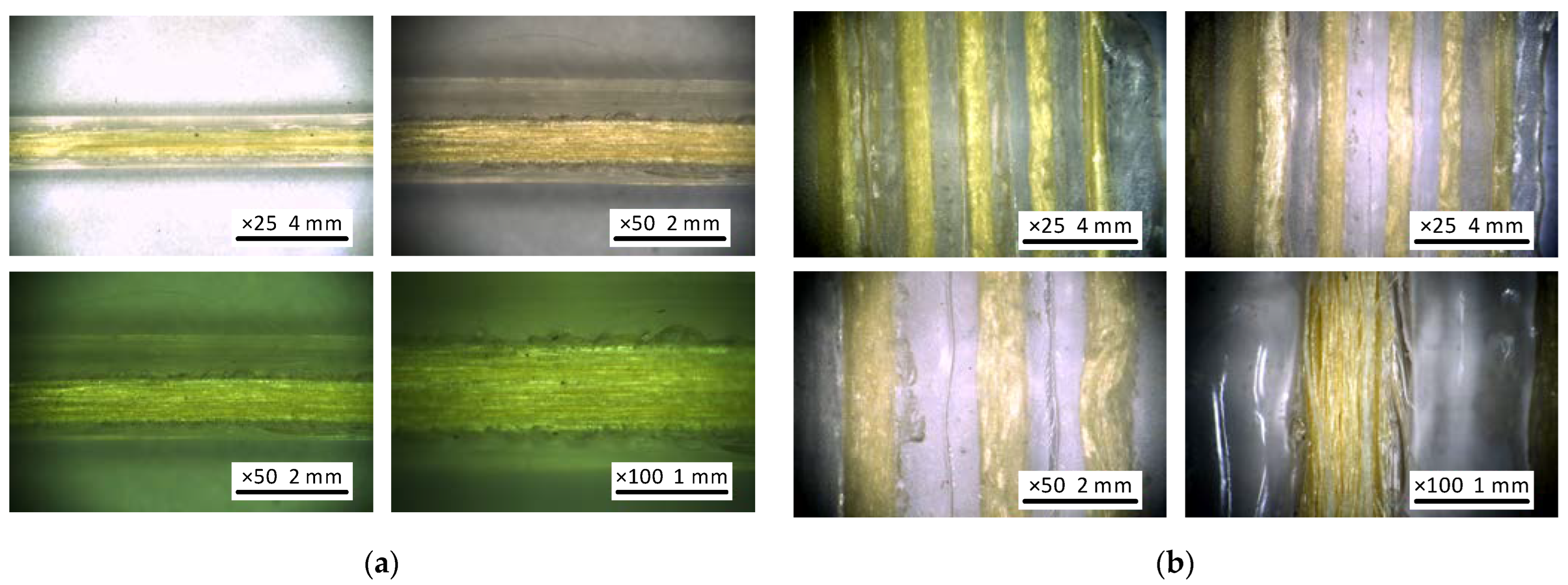
3.1. The ME Quality
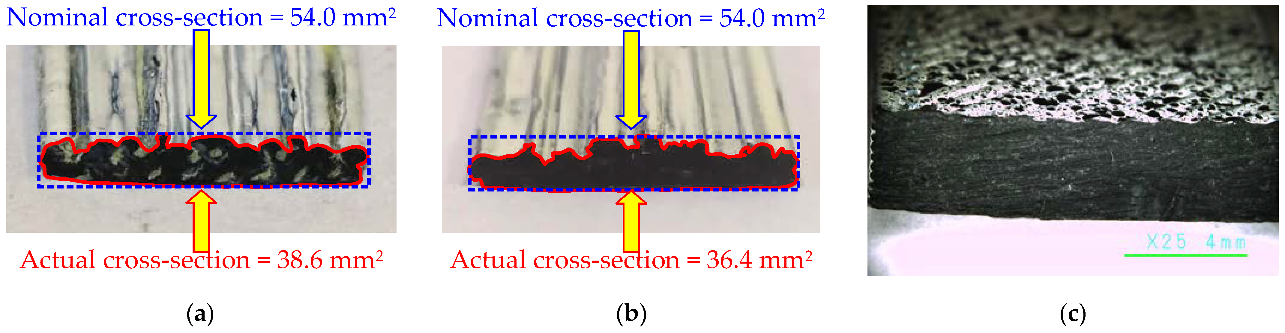
3.2. The Reinforcement Efficiency
3.3. Polymer Recycling Perspectives
- The 40% replacement with recycled material does not negatively affect the PLA strength and modulus of elasticity. At the same time, this modification reduced the PLA cost by almost twice, making the ME technology economically efficient.
- The improvement in the mechanical performance, expressed in terms of the strength, elasticity modulus, and ultimate strength, and the scatter reduction of the test outcomes (Table 2), allows this study to postulate the effectiveness of the PLA replacement with recycled plastic, which should be the object of further research.
4. Conclusions
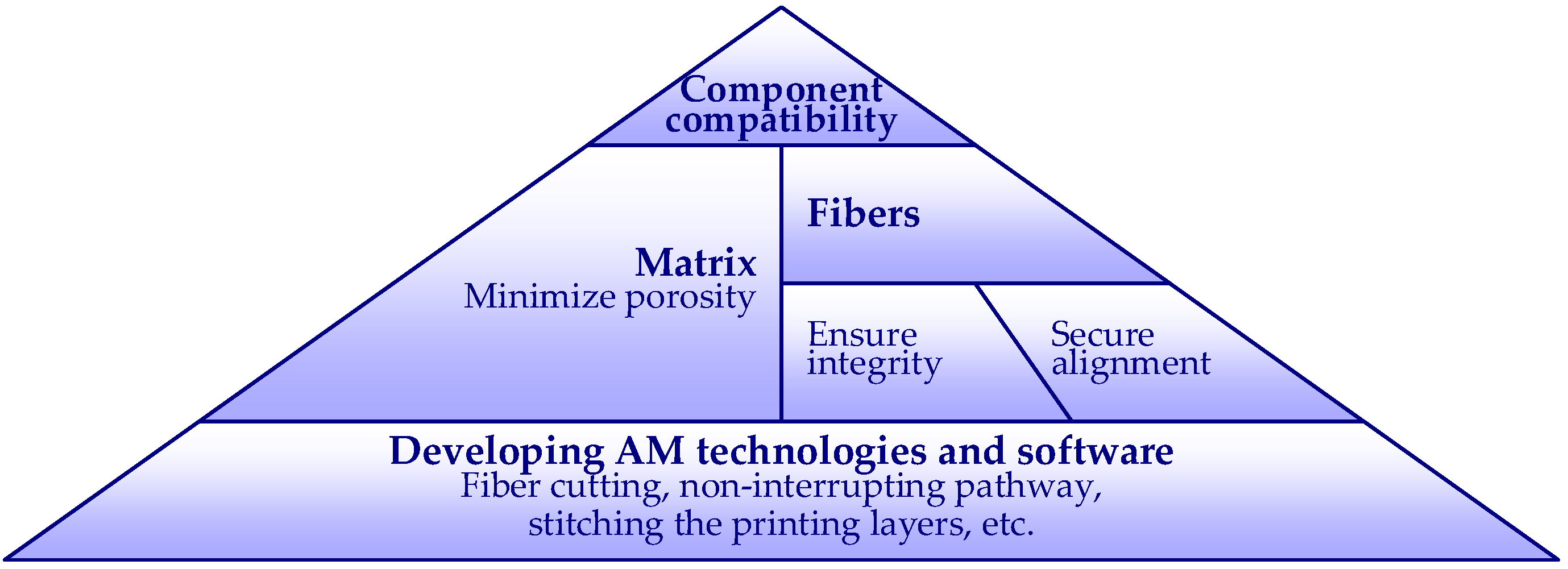
- Continuous reinforcing. Notwithstanding the additive manufacturing (AM) progress, the literature review identified severe limitations of continuous reinforcement related to the material constituents’ compatibility, the composite structure solidification, fibers’ alignment, and adapting material extrusion (ME) technologies.
- ME quality. The case considered in this study exemplifies the duplicated production consequence—the aramid yarn first reinforced the extruded polylactic acid (PLA) filament, i.e., the raw printing material, and a 3D printer produced the reinforced product at the second stage. Such a process accumulates the defects of both manufacturing stages. This feature differentiates the considered technology from the reinforced polymer consolidation processes at the 3D printing stage. However, the raw reinforced filament’s standardized dimensions allow for using typical 3D printers, making the manufacturing process flexible. Further development could focus on developing continuous filament cutting equipment and software for uninterrupted path printing and stitching of the printing layers.
- Printing layout. The mechanical performance of the standardized unreinforced PLA samples corresponds to the parameters provided by the manufacturer. However, the printing pathway and parameters customization reduced the printed material’s load-bearing capacity—the average reduction in mechanical strength was equal to 1.40 times. The continuous reinforcement improved the mechanical performance significantly. However, additional tests are necessary to optimize the printing setup.
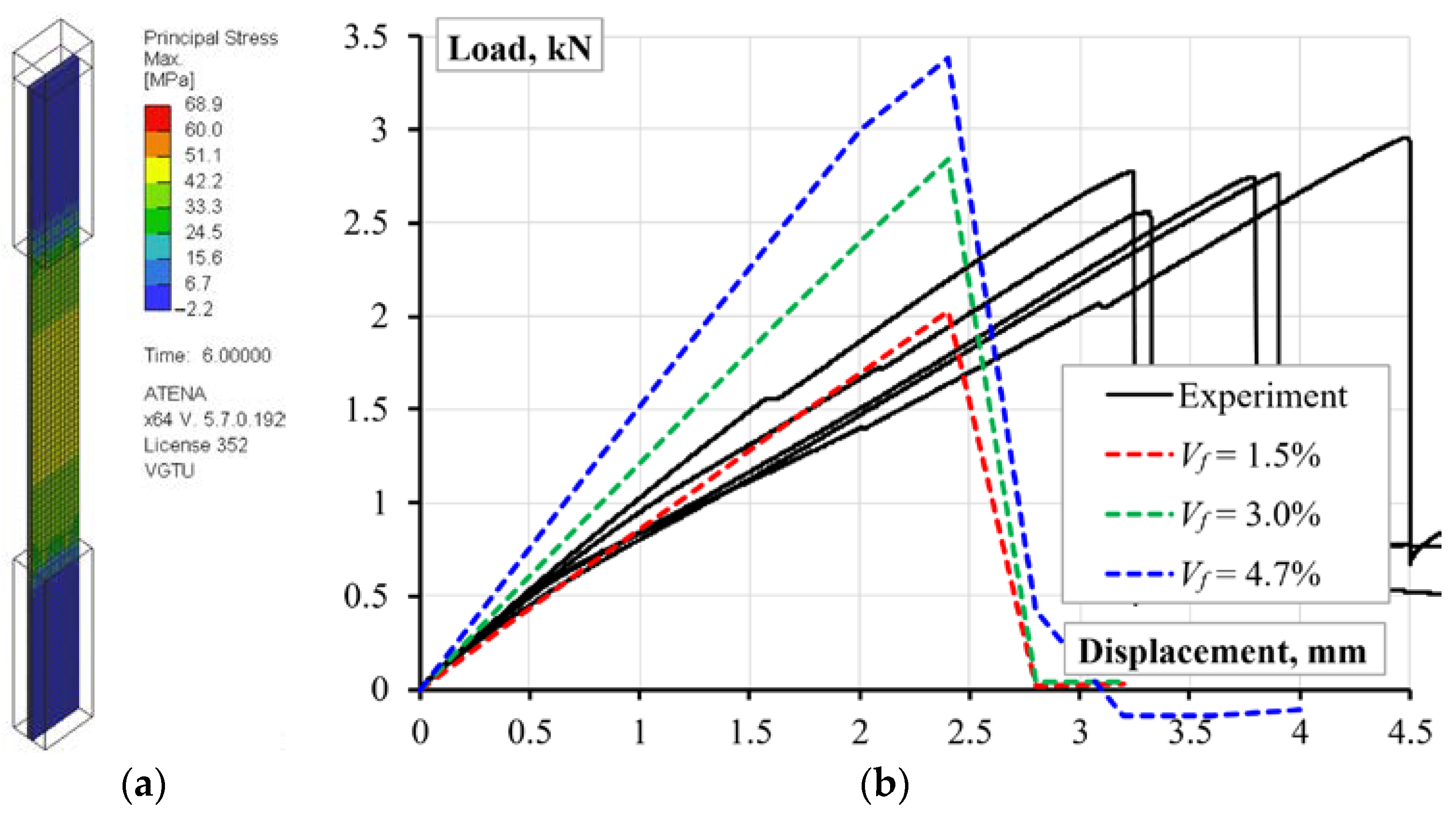
- Reinforcement efficiency. The proposed FE analysis procedure identified the overestimation of axial stiffness and load-bearing capacity—the stiffness and strength terms determine the 31.8% and 63.6% reinforcement efficiency. At the same time, the experimental results reveal beneficial ductility of the developed composite—the deformation corresponding to the maximum resistance of the test specimens more than 1.56 times exceeds the prediction results, determining the further analysis object.
- Recycling possibility. The test results do not demonstrate the recycled polymer’s negative effect on of the ME product performance, supporting findings reported in the literature. The 40% PLA replacement with recycled plastic caused an increase in tensile strength (4.2%), elasticity modulus (5.1%), and ultimate strength (7.5%). This outcome defines the object for further analysis. Moreover, the recycled material reduced the PLA cost by almost twice, making the ME technology economically efficient.
- Further development. In cooperation with Inorega Ltd. (Lithuania), this study developed the continuously reinforced PLA manufacturing equipment that ensures the raw material production process, including the ability for varying constituents (e.g., reinforcing filaments, reinforcement percentage, and recycled plastics replacement ratio). Thus, the proposed technology ensures a flexible fabrication of reinforced components for scientific purposes. The literature review allowed for selecting compatible raw materials, and the printed structure observation supported the choice. However, the experimentally identified mechanical performance of the printed material indicates room for printing technology improvement, including the aligned reinforcement distribution in the printed product. The prospects for industrial application of the proposed analysis concept also determine the target for further research.
Author Contributions
Funding
Data Availability Statement
Conflicts of Interest
References
- Gribniak, V. Special issue “Advanced Composites: From Materials Characterization to Structural Application”. Materials 2020, 13, 5820. [Google Scholar] [CrossRef] [PubMed]
- Gribniak, V.; Rimkus, A.; Plioplys, L.; Misiūnaitė, I.; Boris, R.; Pravilonis, T. Evaluating mechanical efficiency of glass fibres in a polymer profile. Polym. Test. 2021, 102, 107338. [Google Scholar] [CrossRef]
- Gribniak, V.; Rimkus, A.; Plioplys, L.; Misiūnaitė, I.; Garnevičius, M.; Boris, R.; Šapalas, A. An efficient approach to describe the fiber effect on mechanical performance of pultruded GFRP profiles. Front. Mater. 2021, 8, 375. [Google Scholar] [CrossRef]
- Luo, G.M.; Liou, G.Y.; Xiao, H.Z. Using a fiber bragg grating sensor to measure residual strain in the vacuum-assisted resin transfer molding process. Polymers 2022, 14, 1446. [Google Scholar] [CrossRef] [PubMed]
- Liu, Z.; Wang, H.; Yang, L.; Du, J. Research on mechanical properties and durability of flax/glass fiber bio-hybrid FRP composites laminates. Compos. Struct. 2022, 290, 115566. [Google Scholar] [CrossRef]
- Link, T.; Rosenberg, P.; Henning, F. Prediction of gaps in automated tape laying and their influence on porosity in consolidated laminates. J. Compos. Sci. 2022, 6, 207. [Google Scholar] [CrossRef]
- Nazaripoor, H.; Ashrafizadeh, H.; Schultz, R.; Runka, J.; Mertiny, P. Acoustic emission damage detection during three-point bend testing of short glass fiber reinforced composite panels: Integrity assessment. J. Compos. Sci. 2022, 6, 48. [Google Scholar] [CrossRef]
- Xiao, H.; Han, W.; Tang, W.; Duan, Y. An efficient and adaptable path planning algorithm for automated fiber placement based on meshing and multi guidelines. Materials 2020, 13, 4209. [Google Scholar] [CrossRef]
- Maldonado-Hurtado, D.; Madrigal, J.; Penades, A.; Ruiz, R.; Crespo, A.I.; Sales, S. Pultruded FRP beams with embedded fibre bragg grating optical sensors for strain measurement and failure detection. Sensors 2021, 21, 7019. [Google Scholar] [CrossRef]
- Boon, Y.D.; Joshi, S.C.; Bhudolia, S.K. Filament winding and automated fiber placement with in situ consolidation for fiber reinforced thermoplastic polymer composites. Polymers 2021, 13, 1951. [Google Scholar] [CrossRef]
- Fidan, I.; Imeri, A.; Gupta, A.; Hasanov, S.; Nasirov, A.; Elliott, A.; Alifui-Segbaya, F.; Nanami, N. The trends and challenges of fiber reinforced additive manufacturing. Int. J. Adv. Manuf. 2019, 102, 1801–1818. [Google Scholar] [CrossRef]
- Raspall, F.; Velu, R.; Vaheed, N.M. Fabrication of complex 3D composites by fusing automated fiber placement (AFP) and additive manufacturing (AM) technologies. Adv. Manuf. Polym. Compos. Sci. 2019, 5, 6–16. [Google Scholar] [CrossRef]
- Teil, M.; Regazzi, A.; Harthong, B.; Dumont, P.J.J.; Imbault, D.; Putaux, J.-L.; Peyroux, R. Manufacturing of starch-based materials using ultrasonic compression moulding (UCM): Toward a structural application. Heliyon 2021, 7, e06482. [Google Scholar] [CrossRef] [PubMed]
- Frketic, J.; Dickens, T.; Ramakrishnan, S. Automated manufacturing and processing of fiber-reinforced polymer (FRP) composites: An additive review of contemporary and modern techniques for advanced materials manufacturing. Addit. Manuf. 2017, 14, 69–86. [Google Scholar] [CrossRef]
- Wang, Y.; Zhou, Y.; Lin, L.; Corker, J.; Fan, M. Overview of 3D additive manufacturing (AM) and corresponding AM composites. Compos. Part A 2020, 139, 106114. [Google Scholar] [CrossRef]
- Colorado, H.A.; Velásquez, E.I.G.; Monteiro, S.N. Sustainability of additive manufacturing: The circular economy of materials and environmental perspectives. J. Mater. Res. Technol. 2020, 9, 8221–8234. [Google Scholar] [CrossRef]
- Merrington, A. Recycling of plastics. In Applied Plastics Engineering Handbook, 2nd ed.; Kutz, M., Ed.; William Andrew Publishing: Norwich, NY, USA, 2017; pp. 167–189. [Google Scholar]
- Martínez-García, A.; Monzón, M.; Paz, R. Standards for additive manufacturing technologies: Structure and impact. In Additive Manufacturing; Elsevier: Amsterdam, The Netherlands, 2021; pp. 395–408. [Google Scholar]
- Turner, B.N.; Gold, S.A. A review of melt extrusion additive manufacturing processes: II. Materials, dimensional accuracy, and surface roughness. Rapid Prototyp. J. 2015, 21, 250–261. [Google Scholar] [CrossRef]
- Compton, B.G.; Lewis, J.A. 3D-printing of lightweight cellular composites. Adv. Mater. 2014, 26, 5930. [Google Scholar] [CrossRef]
- Shofner, M.L.; Rodríguez-Macías, F.J.; Vaidyanathan, R.; Barrera, E.V. Single wall nanotube and vapor grown carbon fiber reinforced polymers processed by extrusion freeform fabrication. Compos. Part A 2003, 34, 1207–1217. [Google Scholar] [CrossRef]
- Shofner, M.L.; Lozano, K.; Rodriguez-Macias, F.J.; Barrera, E.V. Nanofiber-reinforced polymers prepared by fused deposition modeling. J. Appl. Polym. Sci. 2003, 89, 3081–3090. [Google Scholar] [CrossRef]
- Plymill, A.; Minneci, R.; Greeley, D.A.; Gritton, J. Graphene and carbon nanotube PLA composite feedstock development for fused deposition modeling. Chancellor’s Honors Program Projects, University of Tennessee, 2016.
- Dul, S.; Fambri, L.; Pegoretti, A. Fused deposition modelling with ABS–graphene nanocomposites. Compos. Part A 2016, 85, 181–191. [Google Scholar] [CrossRef]
- Nikzad, M.; Masood, S.H.; Sbarski, I. Thermo-mechanical properties of a highly filled polymeric composites for fused deposition modeling. Mater. Des. 2011, 32, 3448–3456. [Google Scholar] [CrossRef]
- Gray, R.W.; Baird, D.G.; Helge Bøhn, J. Effects of processing conditions on short TLCP fiber reinforced FDM parts. Rapid Prototyp. J. 1998, 4, 14–25. [Google Scholar] [CrossRef]
- Zhong, W.; Li, F.; Zhang, Z.; Song, L.; Li, Z. Short fiber reinforced composites for fused deposition modeling. Mater. Sci. Eng. A 2001, 301, 125–130. [Google Scholar] [CrossRef]
- Tekinalp, H.L.; Kunc, V.; Velez-Garcia, G.M.; Duty, C.E.; Love, L.J.; Naskar, A.K.; Blue, C.A.; Ozcan, S. Highly oriented carbon fiber–polymer composites via additive manufacturing. Compos. Sci. Technol. 2014, 105, 144–150. [Google Scholar] [CrossRef]
- Love, L.J.; Kunc, V.; Rios, O.; Duty, C.E.; Elliott, A.M.; Post, B.K.; Smith, R.J.; Blue, C.A. The importance of carbon fiber to polymer additive manufacturing. J. Mater. Res. 2014, 29, 1893–1898. [Google Scholar] [CrossRef]
- Stepashkin, A.; Chukov, D.; Senatov, F.; Salimon, A.; Korsunsky, A.; Kaloshkin, S. 3D-printed peek-carbon fiber (CF) composites: Structure and thermal properties. Compos. Sci. Technol. 2018, 164, 319–326. [Google Scholar] [CrossRef]
- Saari, M.; Cox, B.; Richer, E.; Krueger, P.S.; Cohen, A.L. Fiber encapsulation additive manufacturing: An enabling technology for 3D printing of electromechanical devices and robotic components. 3D Print. Addit. Manuf. 2015, 2, 32–39. [Google Scholar] [CrossRef]
- Kim, K.; Zhu, W.; Qu, X.; Aaronson, C.; McCall, W.R.; Chen, S.; Sirbuly, D.J. 3D optical printing of piezoelectric nanoparticle–polymer composite materials. ACS Nano 2014, 8, 9799–9806. [Google Scholar] [CrossRef]
- Roper, D.A.; Good, B.L.; McCauley, R.; Yarlagadda, S.; Smith, J.; Good, A.; Pa, P.; Mirotznik, M.S. Additive manufacturing of graded dielectrics. Smart Mater. Struct. 2014, 23, 045029. [Google Scholar] [CrossRef]
- Liu, G.; Xiong, Y.; Zhou, L. Additive manufacturing of continuous fiber reinforced polymer composites: Design opportunities and novel applications. Compos. Commun. 2021, 27, 100907. [Google Scholar] [CrossRef]
- Li, N.; Li, Y.; Liu, S. Rapid prototyping of continuous carbon fiber reinforced polylactic acid composites by 3D printing. J. Mater. Process. Technol. 2016, 238, 218–225. [Google Scholar] [CrossRef]
- Matsuzaki, R.; Ueda, M.; Namiki, M.; Jeong, T.-K.; Asahara, H.; Horiguchi, K.; Nakamura, T.; Todoroki, A.; Hirano, Y. Three-dimensional printing of continuous-fiber composites by in-nozzle impregnation. Sci. Rep. 2016, 6, 23058. [Google Scholar] [CrossRef]
- Melenka, G.W.; Cheung, B.K.O.; Schofield, J.S.; Dawson, M.R.; Carey, J.P. Evaluation and prediction of the tensile properties of continuous fiber-reinforced 3D printed structures. Compos. Struct. 2016, 153, 866–875. [Google Scholar] [CrossRef]
- Tian, X.; Liu, T.; Yang, C.; Wang, Q.; Li, D. Interface and performance of 3D printed continuous carbon fiber reinforced PLA composites. Compos. Part A 2016, 88, 198–205. [Google Scholar] [CrossRef]
- Van Der Klift, F.; Koga, Y.; Todoroki, A.; Ueda, M.; Hirano, Y.; Matsuzaki, R. 3D printing of continuous carbon fibre reinforced thermo-plastic (CFRTP) tensile test specimens. Open J. Compos. Mater. 2016, 6, 18. [Google Scholar] [CrossRef]
- Bettini, P.; Alitta, G.; Sala, G.; Di Landro, L. Fused deposition technique for continuous fiber reinforced thermoplastic. J. Mater. Eng. Perform. 2017, 26, 843–848. [Google Scholar] [CrossRef]
- Dickson, A.N.; Barry, J.N.; McDonnell, K.A.; Dowling, D.P. Fabrication of continuous carbon, glass and kevlar fibre reinforced polymer composites using additive manufacturing. Addit. Manuf. 2017, 16, 146–152. [Google Scholar] [CrossRef]
- Tian, X.; Liu, T.; Wang, Q.; Dilmurat, A.; Li, D.; Ziegmann, G. Recycling and remanufacturing of 3D printed continuous carbon fiber reinforced PLA composites. J. Clean. Prod. 2017, 142, 1609–1618. [Google Scholar] [CrossRef]
- Vaneker, T. Material extrusion of continuous fiber reinforced plastics using commingled yarn. Procedia CIRP 2017, 66, 317–322. [Google Scholar] [CrossRef]
- Caminero, M.; Chacón, J.; García-Moreno, I.; Rodríguez, G. Impact damage resistance of 3D printed continuous fibre reinforced thermoplastic composites using fused deposition modelling. Compos. Part B 2018, 148, 93–103. [Google Scholar] [CrossRef]
- Goh, G.D.; Dikshit, V.; Nagalingam, A.P.; Goh, G.L.; Agarwala, S.; Sing, S.L.; Wei, J.; Yeong, W.Y. Characterization of mechanical properties and fracture mode of additively manufactured carbon fiber and glass fiber reinforced thermoplastics. Mater. Des. 2018, 137, 79–89. [Google Scholar] [CrossRef]
- Hao, W.; Liu, Y.; Zhou, H.; Chen, H.; Fang, D. Preparation and characterization of 3D printed continuous carbon fiber reinforced thermosetting composites. Polym. Test. 2018, 65, 29–34. [Google Scholar] [CrossRef]
- Yu, T.; Zhang, Z.; Song, S.; Bai, Y.; Wu, D. Tensile and flexural behaviors of additively manufactured continuous carbon fiber-reinforced polymer composites. Compos. Struct. 2019, 225, 111147. [Google Scholar] [CrossRef]
- Kalsoom, U.; Nesterenko, P.N.; Paull, B. Recent developments in 3D printable composite materials. RSC Adv. 2016, 6, 60355–60371. [Google Scholar] [CrossRef]
- Babagowda; Kadadevara Math, R.S.; Goutham, R.; Srinivas Prasad, K.R. Study of effects on mechanical properties of PLA filament which is blended with recycled PLA materials. In IOP Conference Series: Materials Science and Engineering; IOP Publishing: Bristol, UK, 2018; Volume 310, p. 012103. [Google Scholar]
- Lanzotti, A.; Martorelli, M.; Maietta, S.; Gerbino, S.; Penta, F.; Gloria, A. A comparison between mechanical properties of specimens 3D printed with virgin and recycled PLA. Procedia CIRP 2019, 79, 143–146. [Google Scholar] [CrossRef]
- Zhao, P.; Rao, C.; Gu, F.; Sharmin, N.; Fu, J. Close-looped recycling of polylactic acid used in 3D printing: An experimental investigation and life cycle assessment. J. Clean. Prod. 2018, 197, 1046–1055. [Google Scholar] [CrossRef]
- Cruz Sanchez, F.A.; Boudaoud, H.; Hoppe, S.; Camargo, M. Polymer recycling in an open-source additive manufacturing context: Mechanical issues. Addit. Manuf. 2017, 17, 87–105. [Google Scholar] [CrossRef]
- Zhao, X.G.; Hwang, K.-J.; Lee, D.; Kim, T.; Kim, N. Enhanced mechanical properties of self-polymerized polydopamine-coated recycled PLA filament used in 3D printing. Appl. Surf. Sci. 2018, 441, 381–387. [Google Scholar] [CrossRef]
- Paciorek-Sadowska, J.; Borowicz, M.; Isbrandt, M. New poly(lactide-urethane-isocyanurate) foams based on bio-polylactide waste. Polymers 2019, 11, 481. [Google Scholar] [CrossRef] [PubMed] [Green Version]
- ASTM D638-14; Standard Test Method for Tensile Properties of Plastics. ASTM International: West Conshohocken, PA, USA, 2015.
- ASTM D3039/D3039M-17; Standard Test Method for Tensile Properties of Polymer Matrix Composite Materials. ASTM International: West Conshohocken, PA, USA, 2017.
- ISO 12232; Photography–Digital Still Cameras–Determination of Exposure index, ISO Speed Ratings, Standard Output Sensitivity, and Recommended Exposure Index. ISO: Geneva, Switzerland, 2019.
- Peinado, V.; Castell, P.; García, L.; Fernández, Á. Effect of extrusion on the mechanical and rheological properties of a reinforced poly(lactic acid): Reprocessing and recycling of biobased materials. Materials 2015, 8, 7106–7117. [Google Scholar] [CrossRef] [PubMed]
- Anderson, I. Mechanical properties of specimens 3D printed with virgin and recycled polylactic acid. 3D Print. Addit. Manuf. 2017, 4, 110–115. [Google Scholar] [CrossRef]
- Mohammadizadeh, M.; Fidan, I. Tensile performance of 3D-printed continuous fiber-reinforced nylon composites. J. Manuf. Mater. Process. 2021, 5, 68. [Google Scholar] [CrossRef]
- Hu, Q.; Duan, Y.; Zhang, H.; Liu, D.; Yan, B.; Peng, F. Manufacturing and 3D printing of continuous carbon fiber prepreg filament. J. Mater. Sci. 2018, 53, 1887–1898. [Google Scholar] [CrossRef]
- Goh, G.D.; Yap, Y.L.; Agarwala, S.; Yeong, W.Y. Recent progress in additive manufacturing of fiber reinforced polymer composite. Adv. Mater. Technol. 2019, 4, 1800271. [Google Scholar] [CrossRef]
- Abtew, M.A.; Boussu, F.; Bruniaux, P.; Liu, H. Fabrication and mechanical characterization of dry three-dimensional warp interlock para-aramid woven fabrics: Experimental methods toward applications in composite reinforcement and soft body armor. Materials 2020, 13, 4233. [Google Scholar] [CrossRef] [PubMed]
- Gribniak, V.; Rimkus, A.; Torres, L.; Jakstaite, R. Deformation analysis of RC ties: Representative geometry. Struct. Concr. 2017, 18, 634–647. [Google Scholar] [CrossRef]
- Cervenka, V.; Rimkus, A.; Gribniak, V.; Cervenka, J. Simulation of the crack width in reinforced concrete beams based on concrete fracture. Theor. Appl. Fract. Mech. 2022, 121, 103428. [Google Scholar] [CrossRef]
- Abouzaid, K.; Bassir, D.; Guessasma, S.; Yue, H. Modelling the process of fused deposition modelling and the effect of temperature on the mechanical, roughness, and porosity properties of resulting composite products. Mech. Compos. Mater. 2021, 56, 805–816. [Google Scholar] [CrossRef]


| Ref. | Fiber/Matrix Type | Outcome | Strength [MPa] |
|---|---|---|---|
| [35] | Carbon fiber (34vol%)/PLA | Flexural strength: 156 MPa | 91 |
| [36] | Carbon jute (40–50vol%)/PLA | Elastic modulus: 19.5 GPa | 185 |
| [37] | Aramid fiber/Nylon | Elastic modulus (4vol%): 1.78 GPa Elastic modulus (8vol%): 6.92 GPa Elastic modulus (10vol%): 9.0 GPa | 31.1 58.8 83.0 |
| [38] | Carbon fiber (1K bundle, 27wt%)/PLA | Flexural strength: 335 MPa Flexural modulus: 30 GPa | – |
| [39] | Carbon fiber (34.5vol%)/Nylon | Elastic modulus: 35.7 GPa | 475 |
| [40] | Aramid fiber (8.6vol%)/PLA | The triple and sextuple increase in tensile modulus and strength regarding unreinforced reference | 206 |
| [41] | Carbon fiber (11vol%)/Nylon | Elastic modulus: 7.73 GPa Flexural strength: 250 MPa Flexural modulus: 13.0 GPa | 216 |
| Glass fiber (10vol%)/Nylon | Elastic modulus: 8.42 GPa Flexural strength: 197 MPa Flexural modulus: 4.21 GPa | 206 | |
| Aramid fiber (10vol%)/Nylon | Elastic modulus: 4.98 GPa Flexural strength: 126 MPa Flexural modulus: 6.65 GPa | 164 | |
| [42] | Recycled carbon fiber (8.9vol%)/PLA | Flexural strength: 263 MPa Flexural modulus:13.3 GPa | 260 |
| [43] | Glass fiber (54.8wt%)/Polypropylene | Flexural modulus: 13.1 GPa | – |
| [44] | Carbon fiber/Nylon | Impact strength: 82.3 kJm2 | – |
| Glass fiber/Nylon | Impact strength: 281 kJm2 | – | |
| Aramid fiber/Nylon | Impact strength: 185 kJm2 | – | |
| [45] | Carbon fiber (41vol%)/Nylon | Elastic modulus: 13.0 GPa Flexural strength: 430 MPa Flexural modulus: 38.1 GPa | 450 |
| Glass fiber (35vol%)/Nylon | Elastic modulus: 7.20 GPa Flexural strength: 149 MPa Flexural modulus: 14.7 GPa | 600 | |
| [46] | Carbon fiber (3K)/Epoxy resin | Elastic modulus: 161 GPa Flexural strength: 202 MPa Flexural modulus: 144 GPa | 793 |
| [47] | Carbon fiber (48.7wt%)/Nylon | A 40% increase in flexural strength regarding chopped CFRP samples | 271 |
| Group | Type | Yield Strength [MPa] | Elasticity Modulus [GPa] | Ultimate Strain [%] | |||
|---|---|---|---|---|---|---|---|
| Value | Mean/CV [%] | Value | Mean/CV [%] | Value | Mean/CV [%] | ||
| Unreinforced (Section 2.1) | Reference Prusa | 40.8 | 42.1/ 3.61 | 2.15 | 2.21/ 4.37 | 4.01 | 4.35/ 15.2 |
| 42.6 | 2.28 | 4.48 | |||||
| 41.3 | 2.24 | 4.24 | |||||
| 44.6 | 2.33 | 5.37 | |||||
| 40.5 | 2.06 | 3.39 | |||||
| 42.5 | 2.21 | 4.60 | |||||
| Reference Inorega | 44.2 | 42.1/ 4.95 | 2.32 | 2.23/ 4.83 | 3.91 | 4.16/ 5.81 | |
| 43.0 | 2.28 | 4.11 | |||||
| 42.5 | 2.02 | 4.49 | |||||
| 43.9 | 2.24 | 4.27 | |||||
| 39.3 | 2.24 | 4.33 | |||||
| 39.8 | 2.29 | 3.88 | |||||
| Recycled Inorega | 43.8 | 43.9/ 1.26 | 2.32 | 2.35/ 3.05 | 3.92 | 4.47/ 8.79 | |
| 43.2 | 2.25 | 4.37 | |||||
| 44.2 | 2.37 | 4.23 | |||||
| 43.6 | 2.31 | 4.93 | |||||
| 43.7 | 2.37 | 4.91 | |||||
| 44.8 | 2.46 | 4.48 | |||||
| Reinforced (Section 2.2) | Reference (unreinforced) Inorega | 33.3 | 31.4/ 14.4 | 1.80 | 1.63/ 7.07 | 2.31 | 2.43/ 12.5 |
| 28.6 | 1.63 | 2.17 | |||||
| 38.4 | 1.63 | 2.95 | |||||
| 27.5 | 1.47 | 2.34 | |||||
| 29.0 | 1.62 | 2.37 | |||||
| Reinforced Inorega | 47.3 | 50.8/ 5.12 | 1.93 | 1.66/ 22.0 | 2.77 | 3.13/ 13.5 | |
| 52.3 | 1.50 | 3.17 | |||||
| 50.7 | 2.15 | 2.71 | |||||
| 49.5 | 1.43 | 3.26 | |||||
| 54.1 | 1.29 | 3.75 | |||||
Publisher’s Note: MDPI stays neutral with regard to jurisdictional claims in published maps and institutional affiliations. |
© 2022 by the authors. Licensee MDPI, Basel, Switzerland. This article is an open access article distributed under the terms and conditions of the Creative Commons Attribution (CC BY) license (https://creativecommons.org/licenses/by/4.0/).
Share and Cite
Rimkus, A.; Farh, M.M.; Gribniak, V. Continuously Reinforced Polymeric Composite for Additive Manufacturing—Development and Efficiency Analysis. Polymers 2022, 14, 3471. https://doi.org/10.3390/polym14173471
Rimkus A, Farh MM, Gribniak V. Continuously Reinforced Polymeric Composite for Additive Manufacturing—Development and Efficiency Analysis. Polymers. 2022; 14(17):3471. https://doi.org/10.3390/polym14173471
Chicago/Turabian StyleRimkus, Arvydas, Mahmoud M. Farh, and Viktor Gribniak. 2022. "Continuously Reinforced Polymeric Composite for Additive Manufacturing—Development and Efficiency Analysis" Polymers 14, no. 17: 3471. https://doi.org/10.3390/polym14173471
APA StyleRimkus, A., Farh, M. M., & Gribniak, V. (2022). Continuously Reinforced Polymeric Composite for Additive Manufacturing—Development and Efficiency Analysis. Polymers, 14(17), 3471. https://doi.org/10.3390/polym14173471