
Mechanical and Fire Performance of Innovative Hollow Glue-Laminated Timber Beams


Abstract
:1. Introduction
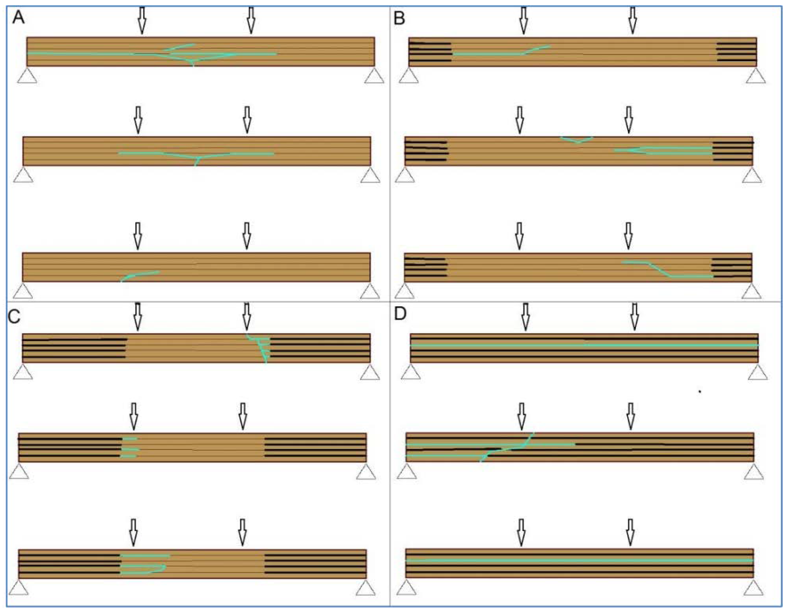
1.1. Debonding and Delamination
1.2. Objectives
- Influence of the adhesives on the load-carrying capacity of glued laminated hollow timber elements;
- Influence of elevated temperature on the adhesive and the load-carrying capacity of glued-laminated hollow timber elements;
- Impact of the perforation of the timber element on the development of temperature towards the interior of the element;
- The effect of the reduced glued surface affects the possible separation of the lamellae-delamination;
- The effect of passive fire protection on the fire resistance of hollow timber beams (one-dimensional and notional charring rate);
- Introduction of all mentioned problems in the form of the analytical or numerical model.
2. Materials and Methods
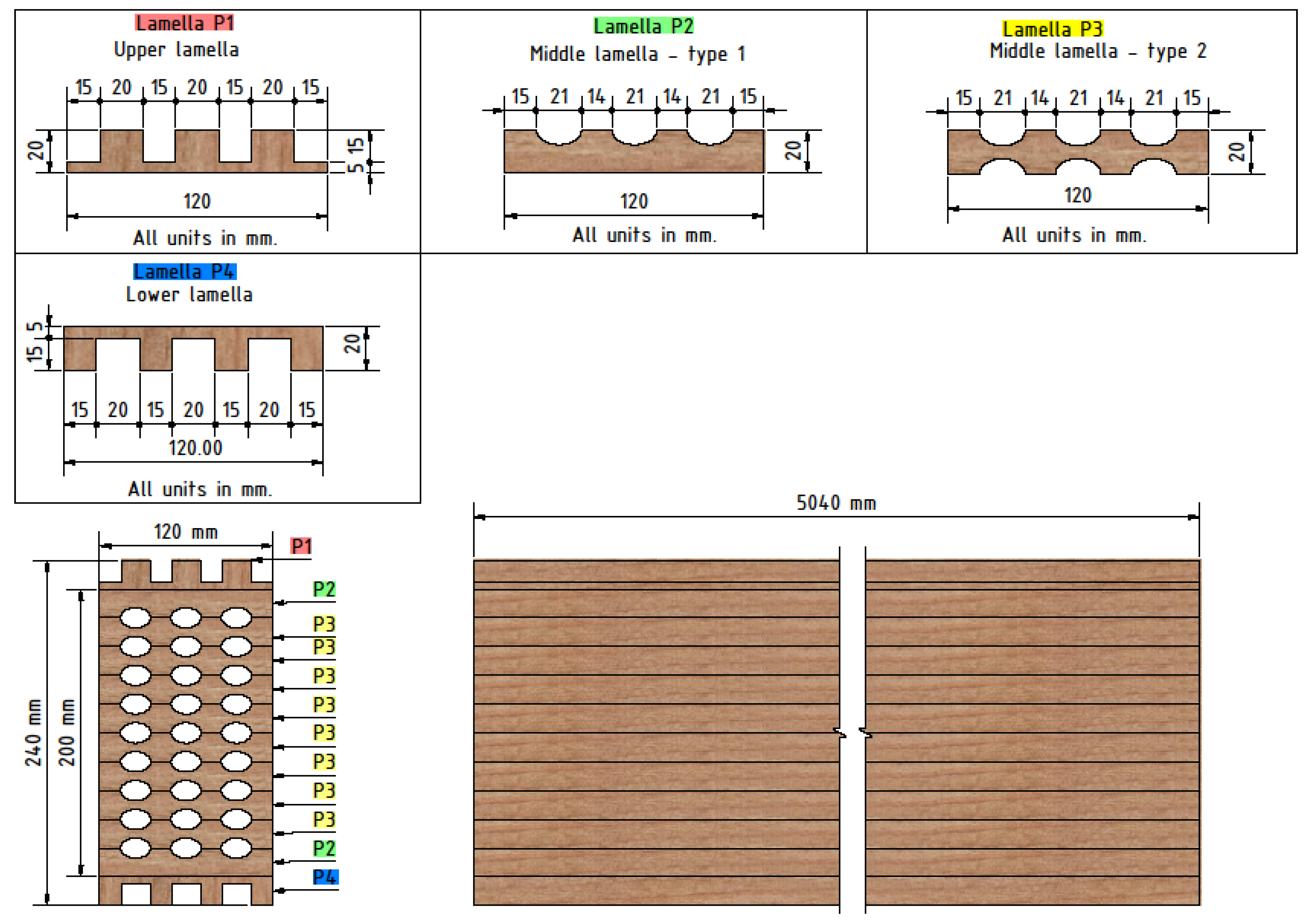
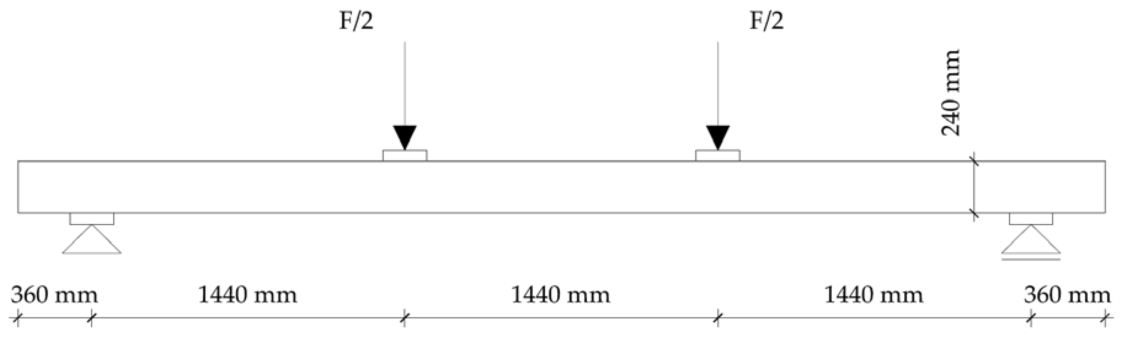
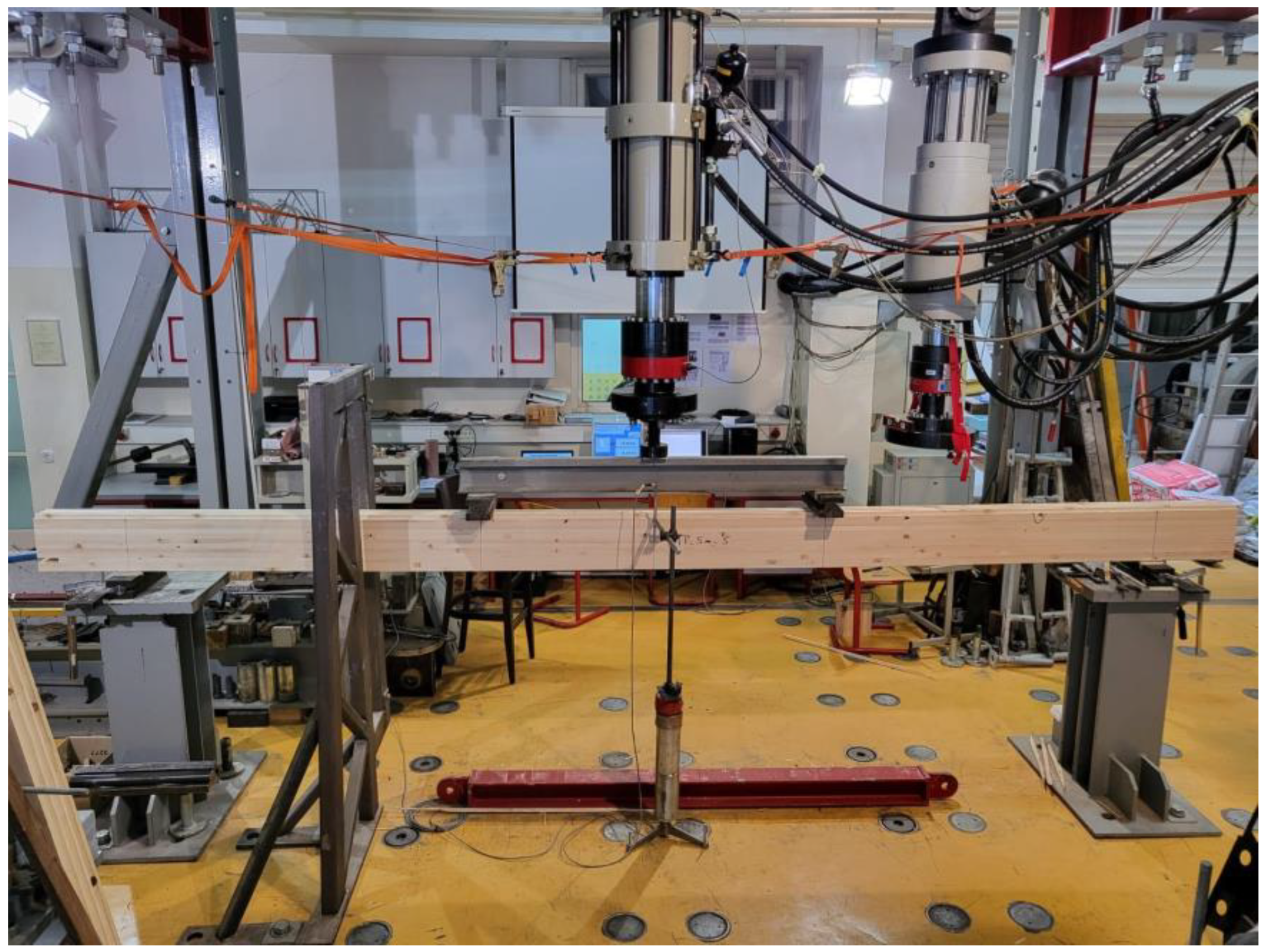
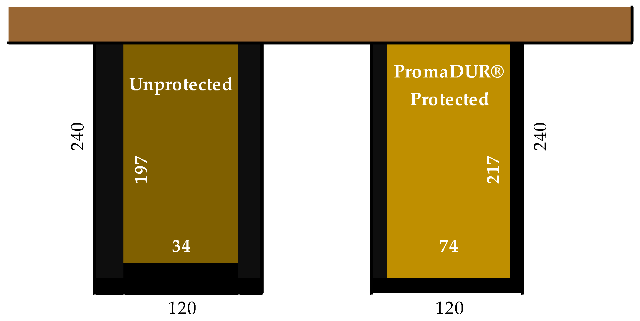
2.1. Preliminary Research—Mechanical Performance of Innovative Hollow Glue-Laminated Timber Beams
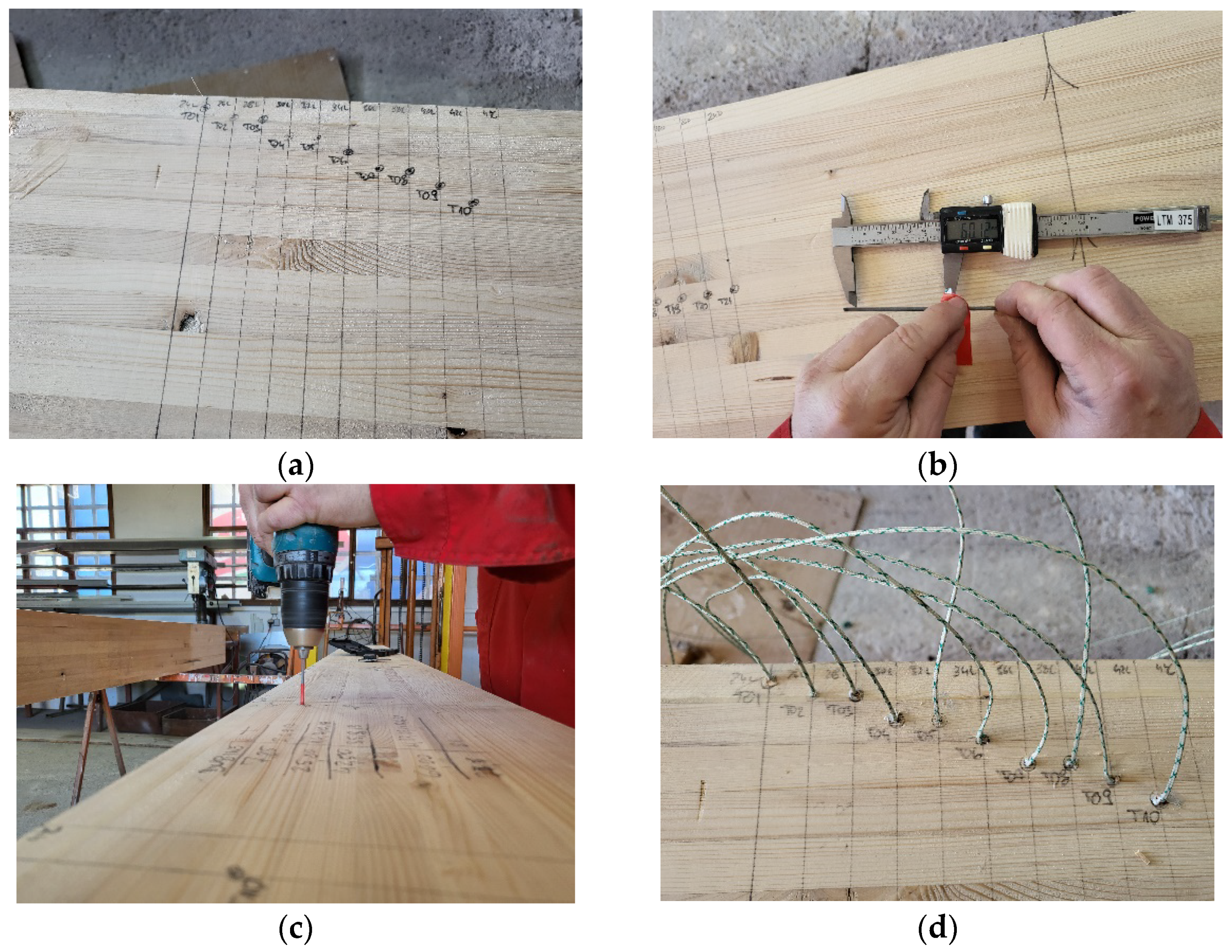
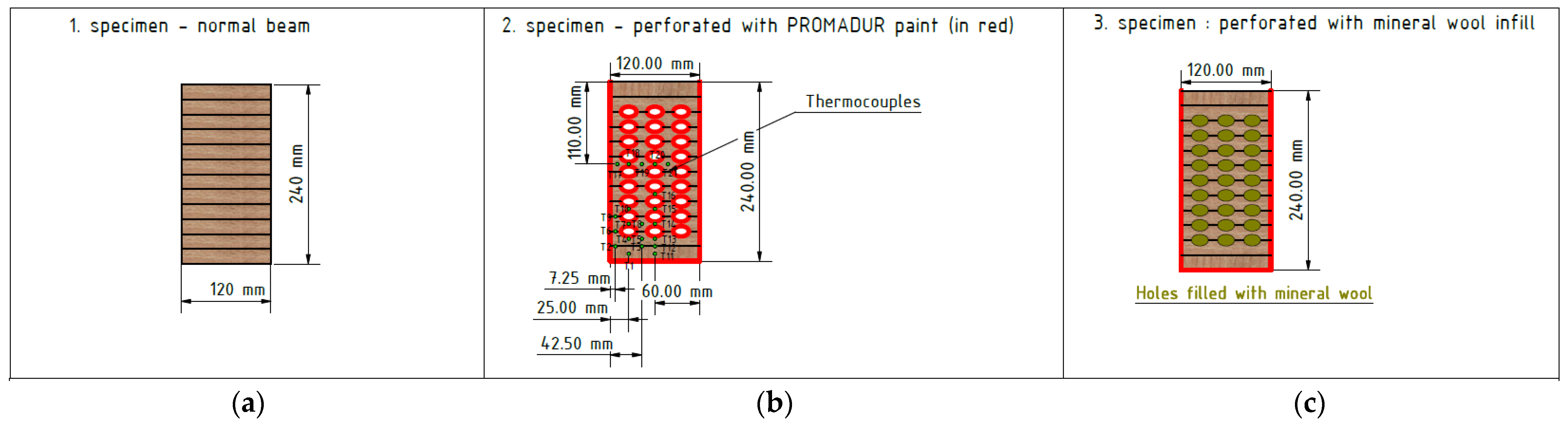
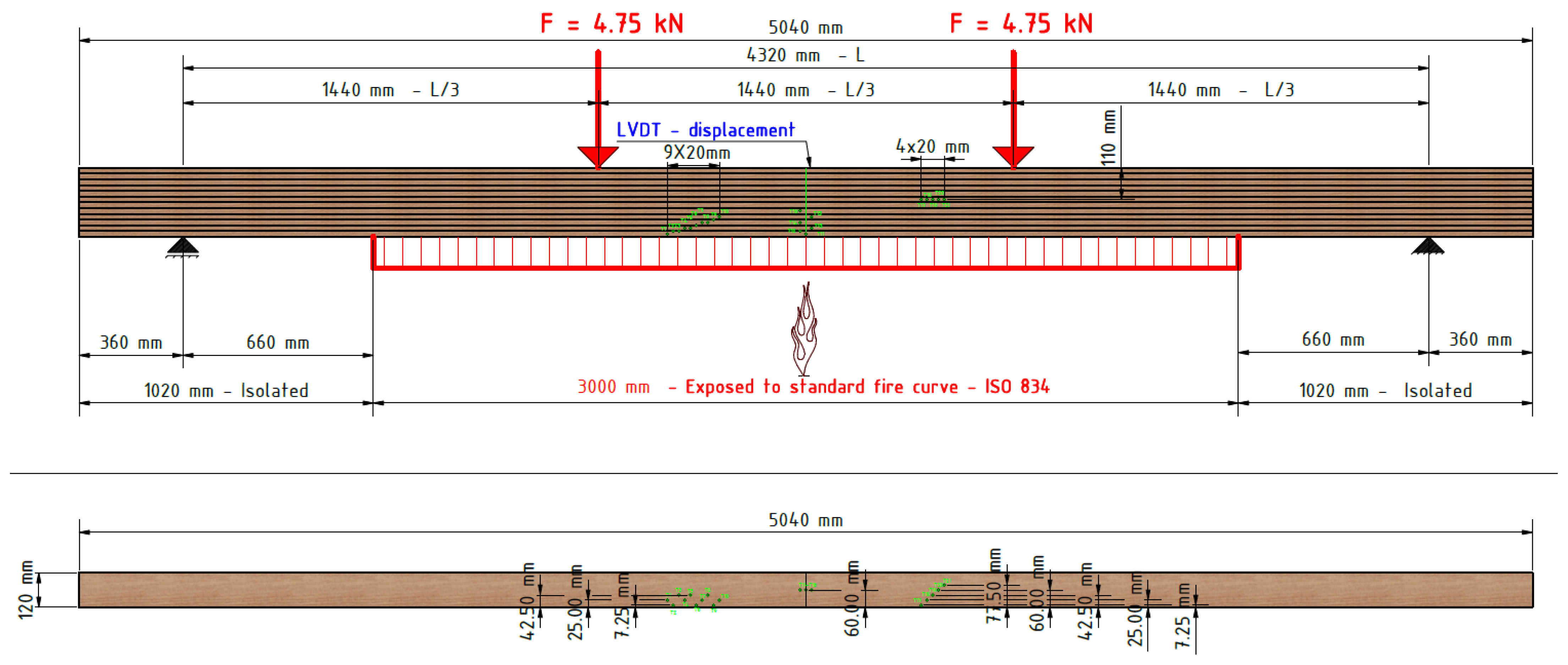
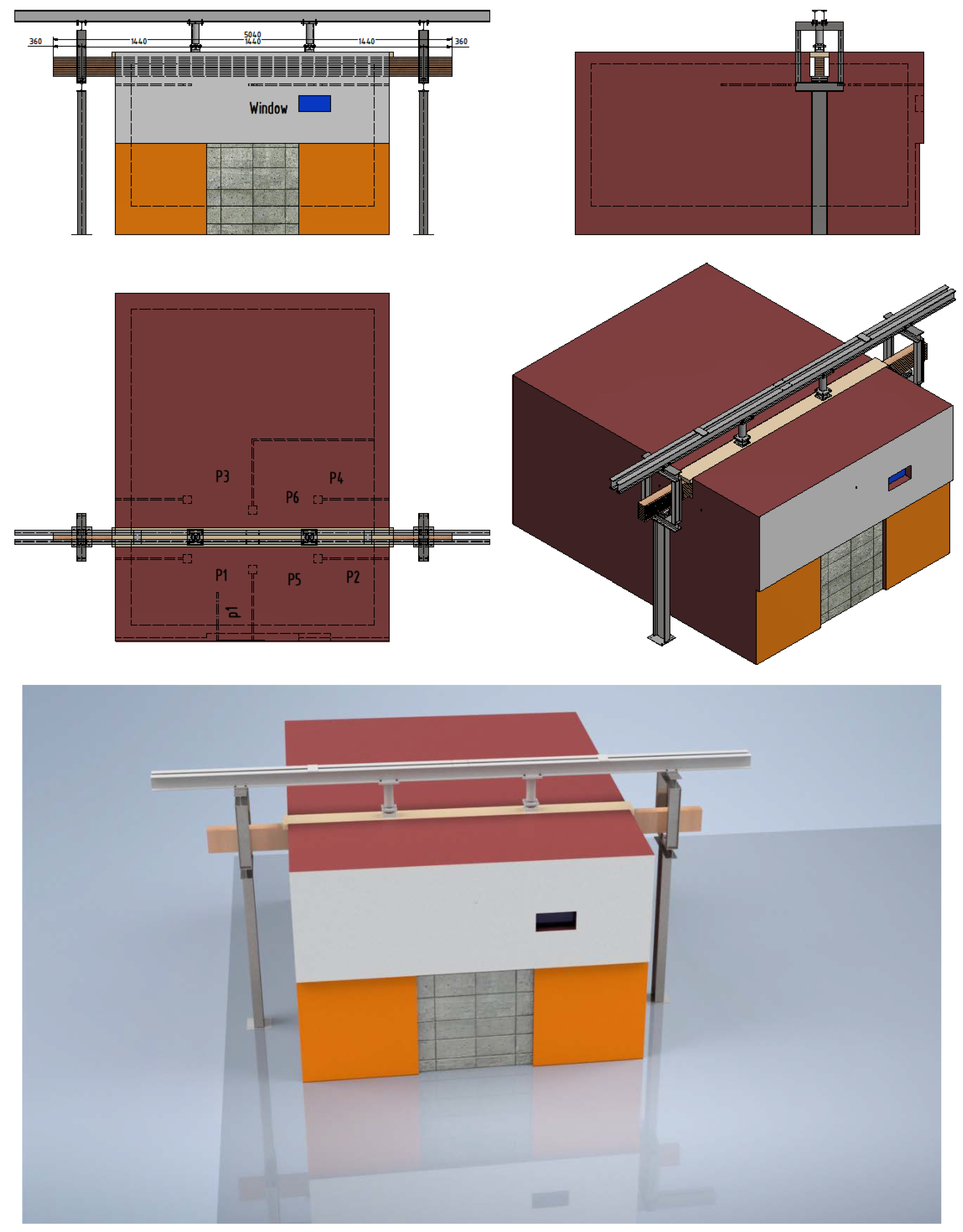
2.2. Fire Tests
3. Results
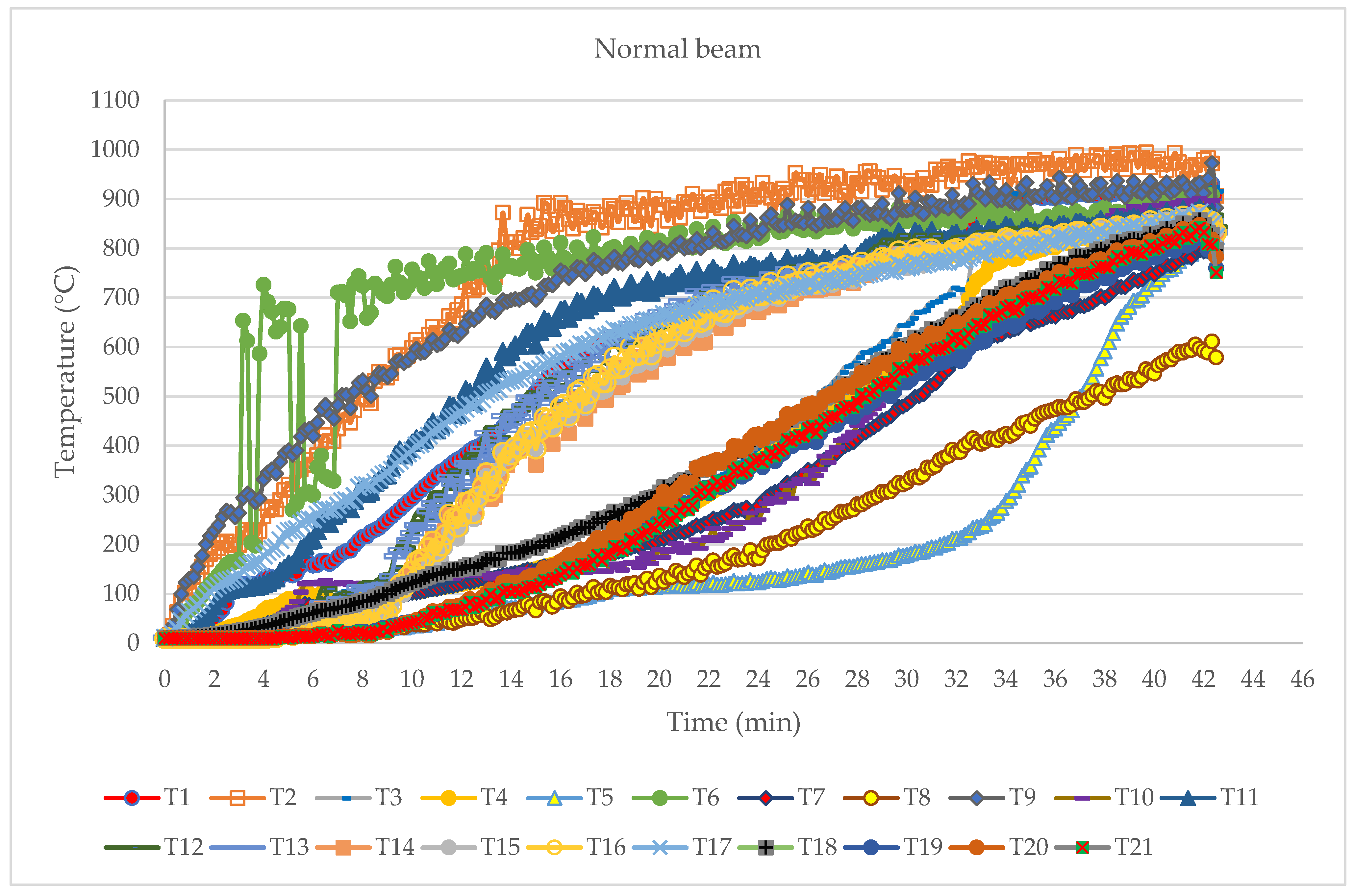
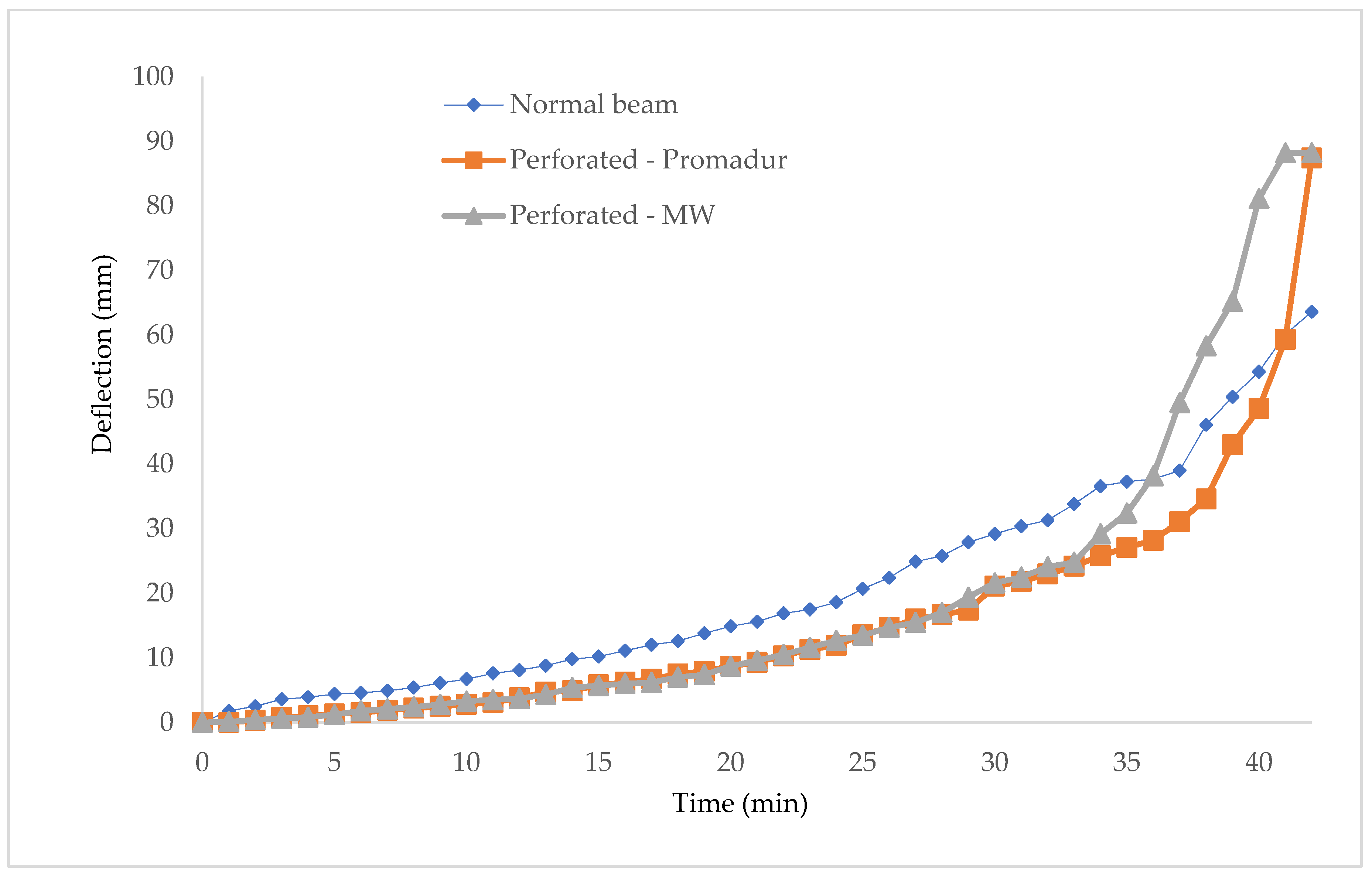
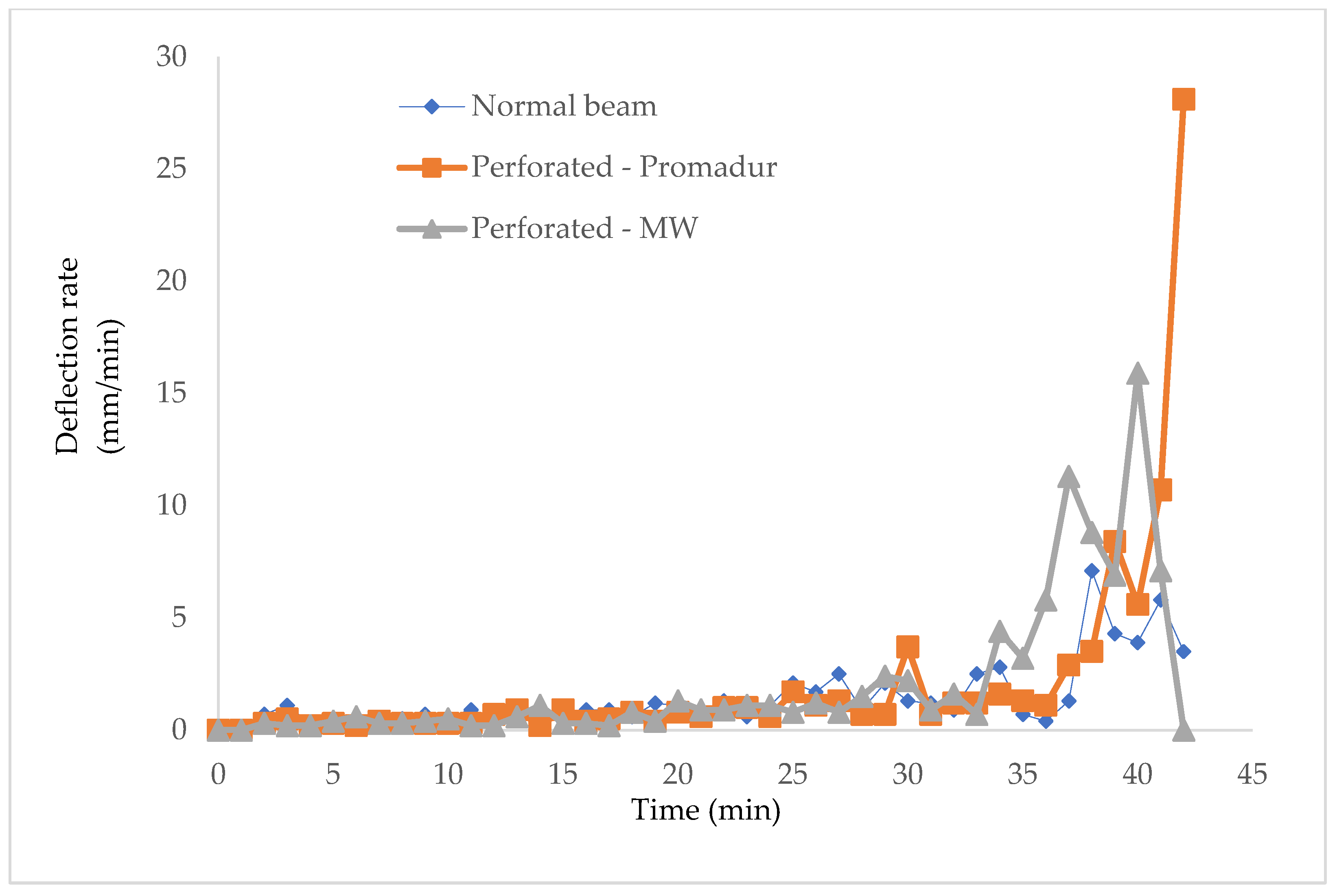
3.1. Normal Beam
3.2. Hollow Beam with Intumescent Paint—Promadur
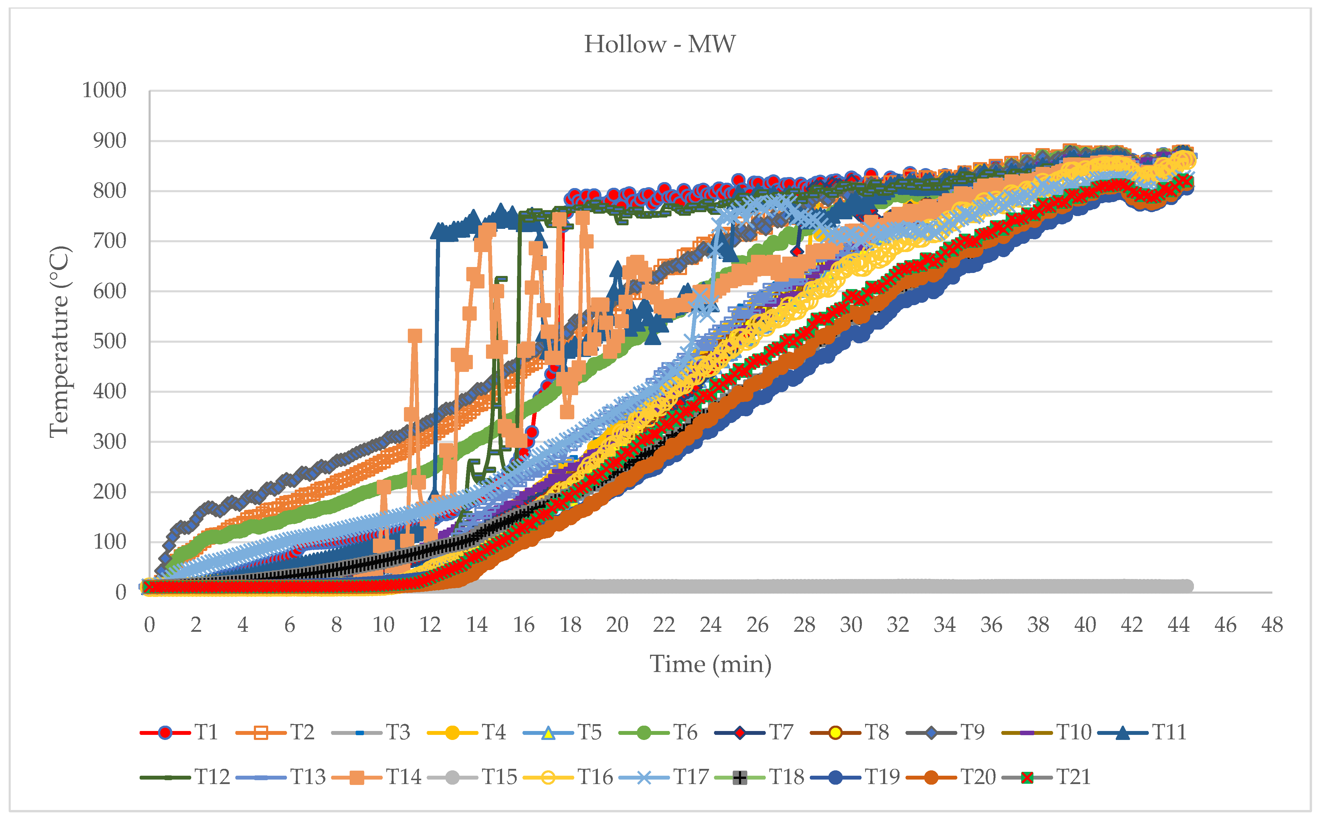
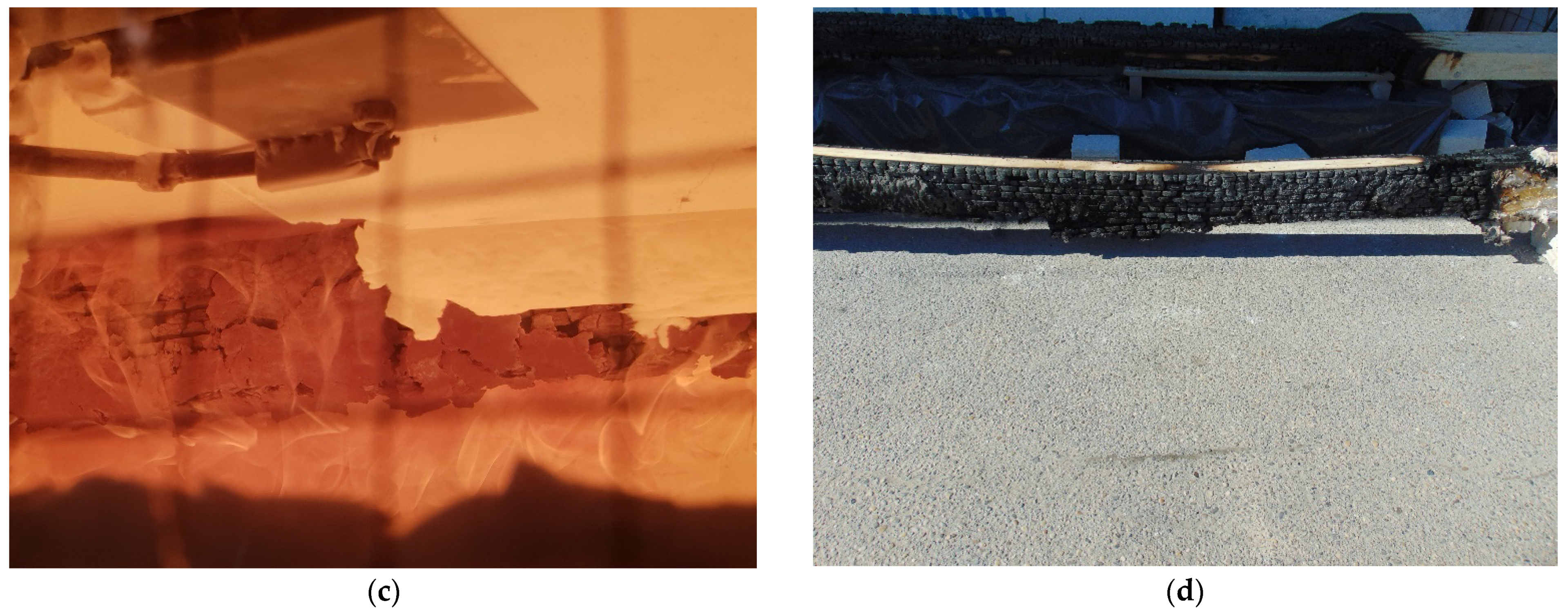
3.3. Hollow Beam with Mineral Wool Infill
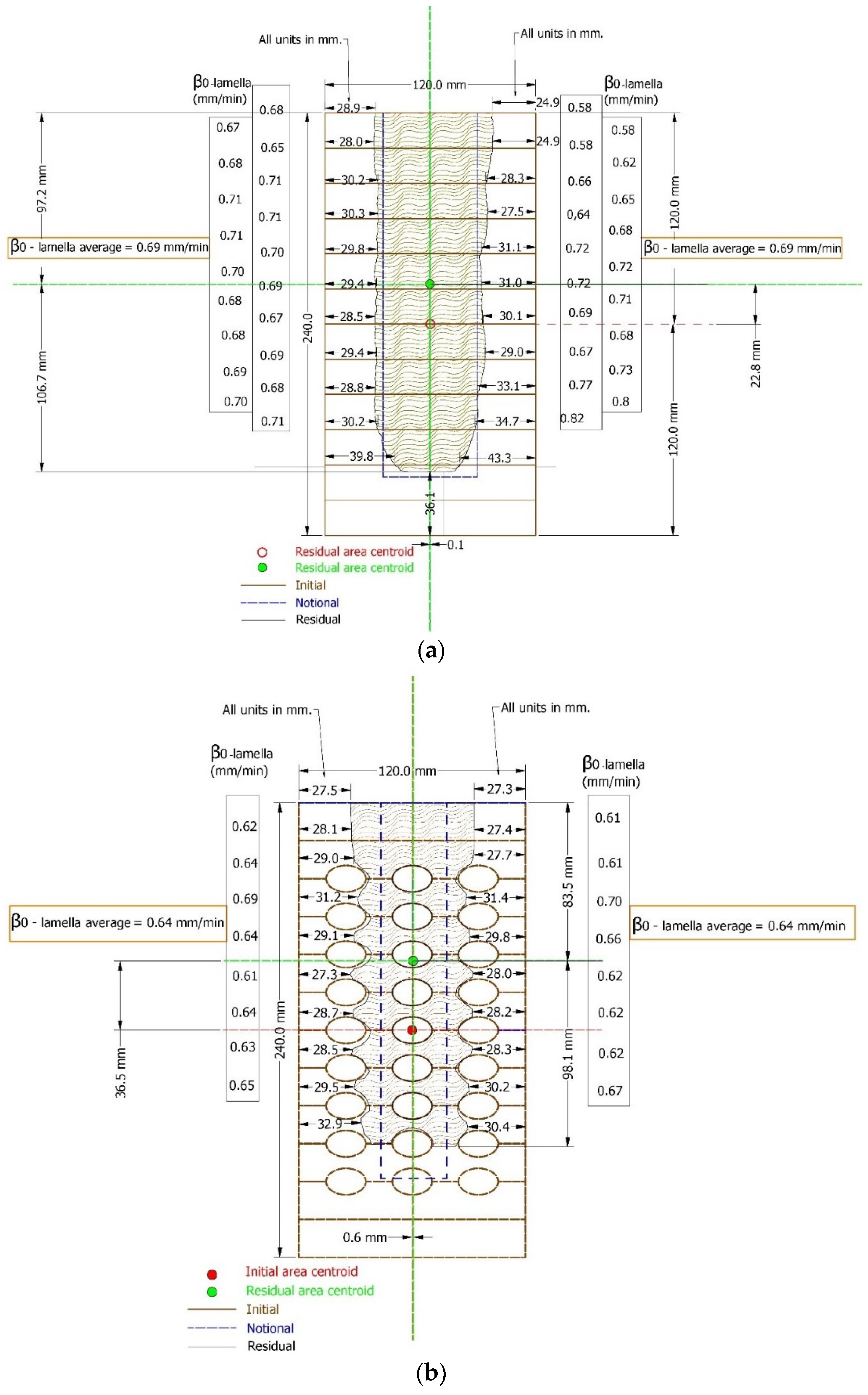
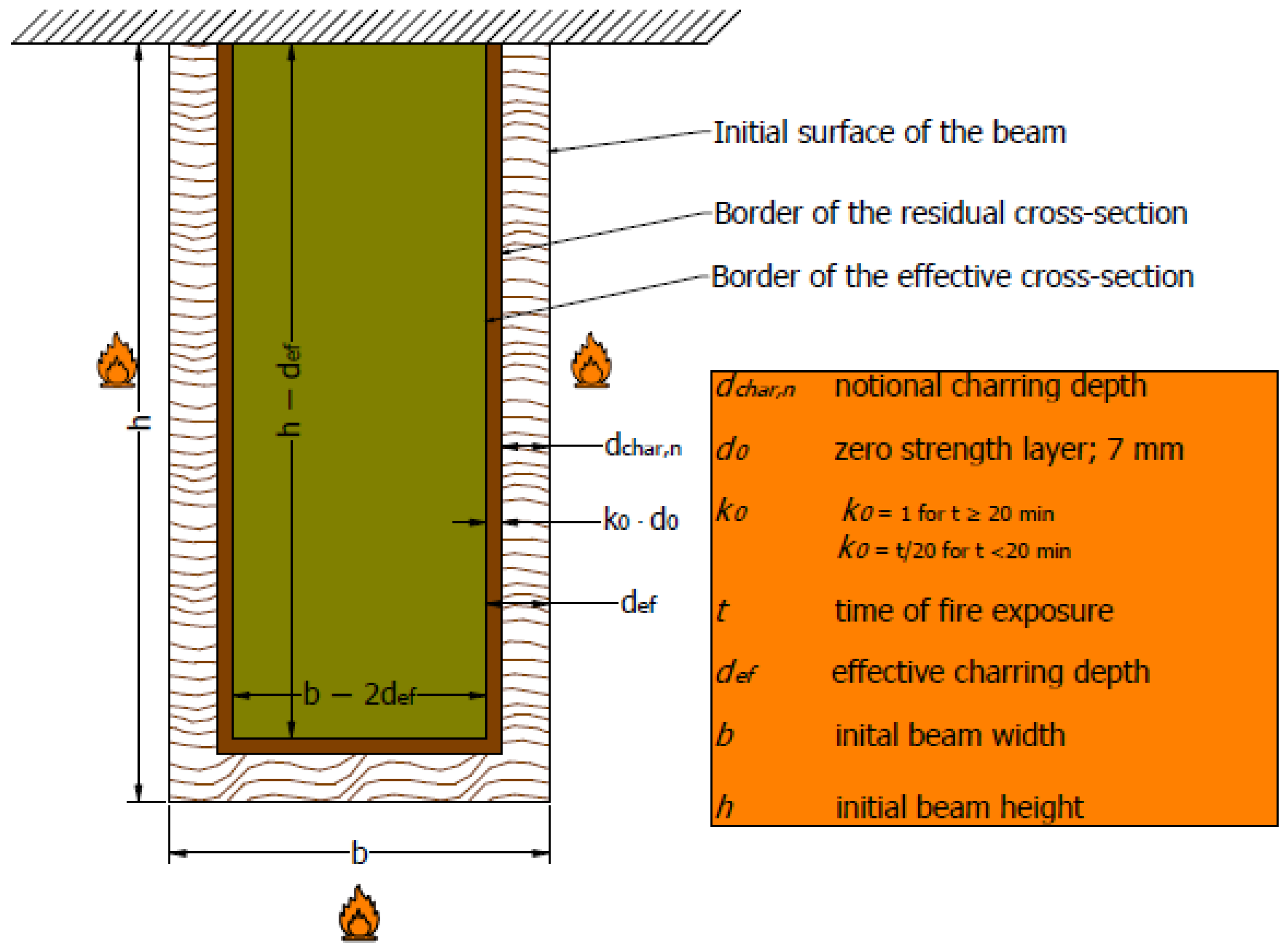
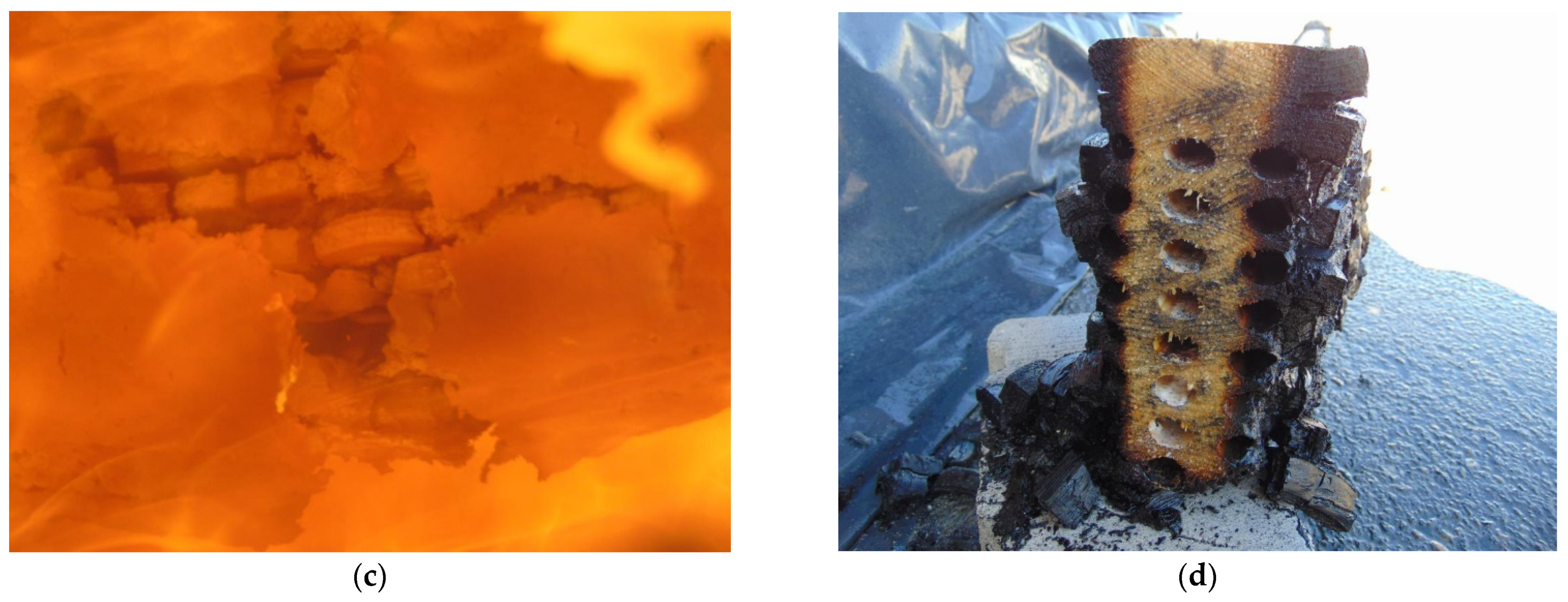
3.4. Charring Behaviour
4. Discussion
5. Conclusions
6. Patents
Author Contributions
Funding
Institutional Review Board Statement
Informed Consent Statement
Data Availability Statement
Acknowledgments
Conflicts of Interest
References
- Sauerbier, P.; Mayer, A.K.; Emmerich, L.; Militz, H. Fire Retardant Treatment of Wood—State of the Art and Future Perspectives. In Proceedings of the International Scientific Conference on Woods & Fire Safety, Štrbské Pleso, Slovakia, 3–6 May 2020; pp. 97–102. [Google Scholar]
- Chu, D.; Mu, J.; Avramidis, S.; Rahimi, S.; Liu, S.; Lai, Z. Functionalized Surface Layer on Poplar Wood Fabricated by Fire Retardant and Thermal Densification. Part 1: Compression Recovery and Flammability. Forests 2019, 10, 955. [Google Scholar] [CrossRef]
- Chu, D.; Mu, J.; Avramidis, S.; Rahimi, S.; Liu, S.; Lai, Z. Functionalized Surface Layer on Poplar Wood Fabricated by Fire Retardant and Thermal Densification. Part 2: Dynamic Wettability and Bonding Strength. Forests 2019, 10, 982. [Google Scholar] [CrossRef]
- Östman, B.; Schmid, J.; Klippel, M.; Just, A.; Werther, N.; Brandon, D. Fire Design of CLT in Europe. Wood Fiber Sci. 2018, 50, 68–82. [Google Scholar] [CrossRef]
- Pravilnik o Otpornosti na Požar i Drugim Zahtjevima koje Građevine Moraju Zadovoljiti u Slučaju Požara. Available online: https://narodne-novine.nn.hr/clanci/sluzbeni/2013_03_29_505.html (accessed on 27 June 2022).
- Rukavina, M.J.; Carević, M.; Pečur, I.B. Zaštita Pročelja zgrada od Požara/Priručnik za Projektiranje i Izvođenje Zaštita Pročelja Zgrada od Požara. Available online: https://www.grad.unizg.hr/images/50014204/Zastita%20procelja%20zgrada%20od%20pozara_Jelcic%20Carevic%20Banjad.pdf (accessed on 3 July 2022).
- Blaß, H.J.; Sandhaas, C. Timber Engineering Principles for Design for Safety; KIT Scientific Publishing: Karlsruhe, Germany, 2017. [Google Scholar]
- Broughton, J.G.; Hutchinson, A.R. Adhesive Systems for Structural Connections in Timber. Int. J. Adhes. Adhes. 2001, 21, 177–186. [Google Scholar] [CrossRef]
- EN 16351:2021; Timber Structures—Cross Laminated Timber—Requirements. Available online: https://standards.iteh.ai/catalog/standards/cen/3f9c8502-609e-4592-9cc2-219dc2ff3720/en-16351-2021 (accessed on 23 June 2022).
- Zelinka, S.L.; Sullivan, K.; Pei, S.; Ottum, N.; Bechle, N.J.; Rammer, D.R.; Hasburgh, L.E. Small Scale Tests on the Performance of Adhesives Used in Cross Laminated Timber (CLT) at Elevated Temperatures. Int. J. Adhes. Adhes. 2019, 95, 102436. [Google Scholar] [CrossRef]
- Emberley, R.; Torero Cullen, J. Cross-Laminated Timber Failure Modes for Fire Conditions. In Proceedings of the Second International Conference on Performance-Based and Life-Cycle Structural Engineering (PLSE 2015), Brisbane, Australia, 9–11 December 2015; School of Civil Engineering, The University of Queensland: Brisbane, QLD, Australia, 2015; pp. 1023–1030. [Google Scholar]
- Crielaard, R.; van de Kuilen, J.W.; Terwel, K.; Ravenshorst, G.; Steenbakkers, P. Self-Extinguishment of Cross-Laminated Timber. Fire Saf. J. 2019, 105, 244–260. [Google Scholar] [CrossRef]
- Su, J.; Lafrance, P.-S.; Hoehler, M.; Bundy, M. Fire Safety Challenges of Tall Wood Buildings-Phase 2: Task 2 & 3-Cross Laminated Timber Compartment Fire Tests. Available online: https://www.nfpa.org/-/media/Files/News-and-Research/Fire-statistics-and-reports/Building-and-life-safety/RFTallWoodBuildingsTask2and3.pdf (accessed on 3 July 2022).
- Schmidt, L. Experimental Study on the Effect of Char Fall Off on the Heat Transfer within Loaded CLT Columns Exposed to Radiant Heating. Master’s Thesis, College of Science and Engineering, The University of Edinburgh, Edinburgh, UK, 2020. [Google Scholar]
- Emberley, R.; Do, T.; Yim, J.; Torero, J.L. Critical Heat Flux and Mass Loss Rate for Extinction of Flaming Combustion of Timber. Fire Saf. J. 2017, 91, 252–258. [Google Scholar] [CrossRef]
- Kucíková, L.; Janda, T.; Šejnoha, M.; Sýkora, J. Experimental Investigation of Fire Resistance of Glt Beams. Int. J. Comput. Methods Exp. Meas. 2020, 8, 99–110. [Google Scholar] [CrossRef]
- Klippel, M.; Frangi, A. Fire Safety of Glued-Laminated Timber Beams in Bending. J. Struct. Eng. 2017, 143, 04017052. [Google Scholar] [CrossRef]
- Fragiacomo, M.; Menis, A.; Clemente, I.; Bochicchio, G.; Ceccotti, A. Fire Resistance of Cross-Laminated Timber Panels Loaded Out of Plane. J. Struct. Eng. 2012, 139, 04013018. [Google Scholar] [CrossRef]
- Menis, A. Fire Resistance of Laminated Veneer Lumber (LVL) and Cross-Laminated Timber (XLAM) Elements. Ph.D. Thesis, Università Degli Studi di Cagliari, Cagliari, Italy, 2012. [Google Scholar]
- Friquin, K.L. Charring Rates of Heavy Timber Structures for Fire Safety Design. Ph.D. Thesis, Norwegian University of Science and Technology, Trondheim, Norway, 2010. [Google Scholar]
- Klippel, M.; Leyder, C.; Frangi, A.; Fontana, M.; Lam, F.; Ceccotti, A. Fire Tests on Loaded Cross-Laminated Timber Wall and Floor Elements. Fire Saf. Sci. 2014, 11, 626–639. [Google Scholar] [CrossRef]
- Čolić, A. Study of the Char Fall-off Phenomenon in Cross-Laminated Timber under Fire Conditions. Master’s Thesis, The University of Edinburgh, Edinburgh, UK, 2021. [Google Scholar]
- Perković, N.; Rajčić, V.; Pranjić, M. Behavioral Assessment and Evaluation of Innovative Hollow Glue-Laminated Timber Elements. Materials 2021, 14, 6911. [Google Scholar] [CrossRef] [PubMed]
- Kleiberit. Deutsches Institut fur Bautechnik. Available online: https://www.kleiberit.com/fileadmin/Content/Documents/EN/Info_Sheets/510_Tragender_Holzbau_GB_US.pdf (accessed on 23 June 2022).
- EN 1995-1-2:2004/A2:2014; Eurocode 5: Design of Timber Structures—Part 1–2: General—Structural Fire Design. Available online: https://www.phd.eng.br/wp-content/uploads/2015/12/en.1995.1.2.2004.pdf (accessed on 27 June 2022).
- Fahrni, R.; Klippel, M.; Just, A.; Ollino, A.; Frangi, A. Fire Tests on Glued-Laminated Timber Beams with Specific Local Material Properties. Fire Saf. J. 2019, 107, 161–169. [Google Scholar] [CrossRef]
- EN 408:2012; Timber Structures—Structural Timber and Glued Laminated Timber—Determination of Some Physical and Mechanical Properties. Available online: https://standards.iteh.ai/catalog/standards/cen/6ffae6c9-5eaf-4c84-8bf3-5132cbfc563c/en-408-2010a1-2012 (accessed on 2 July 2022).
- EN 1363-1:2020; Fire Resistance Tests—Part 1: General Requirements. Available online: https://standards.iteh.ai/catalog/standards/cen/243adbdc-e0e0-43ac-a801-22c8e91e7f3c/en-1363-1-2020 (accessed on 23 June 2022).
- HRN EN 1365-3:2002; Hrvatski Normativni Dokument/HRN4You—Hrvatski Zavod za Norme. Available online: https://repozitorij.hzn.hr/norm/HRN+EN+1365-3%3A2002 (accessed on 23 June 2022).
- DIN EN 1052-1; European Standards. Available online: https://www.en-standard.eu/din-en-1052-1-methods-of-test-for-masonry-part-1-determination-of-compressive-strength/ (accessed on 30 June 2022).
- PROMADUR®—Promat. Available online: https://www.promat.com/en/construction/products-systems/products/intumescent-paints/promadur/ (accessed on 2 July 2022).
- Schmid, J.; König, J.; Just, A. The Reduced Cross-Section Method for the Design of Timber Structures Exposed to Fire-Background, Limitations and New Developments. Struct. Eng. Int. 2012, 22, 514–522. [Google Scholar] [CrossRef]
- Schmid, J.; Just, A.; Klippel, M.; Fragiacomo, M. The Reduced Cross-Section Method for Evaluation of the Fire Resistance of Timber Members: Discussion and Determination of the Zero-Strength Layer. Fire Technol. 2014, 51, 1285–1309. [Google Scholar] [CrossRef]
- Kamenická, Z.; Sandanus, J. Comparison of Simplified and Advanced Design Methods for Determining Mechanical Resistance of Timber Structures Exposed to Fire. Int. Wood Prod. J. 2017, 8, 88–93. [Google Scholar] [CrossRef]
- Hietaniemi, J. A Probabilistic Approach to Wood Charring Rate; VTT Working Papers 31; VTT Information Service: Espoo, Finland, 2005; pp. 1–54. [Google Scholar]
- Mikkola, E. Charring of Wood Based Materials. Fire Saf. Sci. 1991, 3, 547–556. [Google Scholar] [CrossRef]
- EN 13381-7:2019; Test Methods for Determining the Contribution to the Fire Resistance of Structural. Available online: https://standards.iteh.ai/catalog/standards/cen/4d52d75a-658e-4b7b-aebf-99b546b7a20a/en-13381-7-2019 (accessed on 2 July 2022).


| Specimen | Failure Load (kN) | Final Displacement (mm) | Moisture (%) |
|---|---|---|---|
| MP_5m_1 | 66.36 | 84.075 | 9.5 |
| MP_5m_1 | 47.50 | 59.835 | 9.9 |
| MP_5m_3 | 44.64 | 66.743 | 10.6 |
| MP_5m_4 | 59.10 | 75.639 | 9.6 |
| MP_5m_5 | 55.84 | 65.283 | 9.6 |
| MP_5m_6 | 62.00 | 74.969 | 10.1 |
| Average | 55.90 | 71.09 | 9.93 |
| Standard deviation | 8.42 | 8.76 | 0.54 |
| Variation coefficient | 15.05% | 12.32% | 5.45% |
| Specimen | Failure Load (kN) | Final Displacement (mm) | Moisture (%) |
|---|---|---|---|
| ME_5m_1 | 31.48 | 54.625 | 11.2 |
| ME_5m_2 | 46.60 | 71.522 | 9.6 |
| ME_5m_3 | 29.53 | 51.443 | 10.2 |
| ME_5m_4 | 39.05 | 61.094 | 9.9 |
| ME_5m_5 | 28.85 | 52.289 | 9.2 |
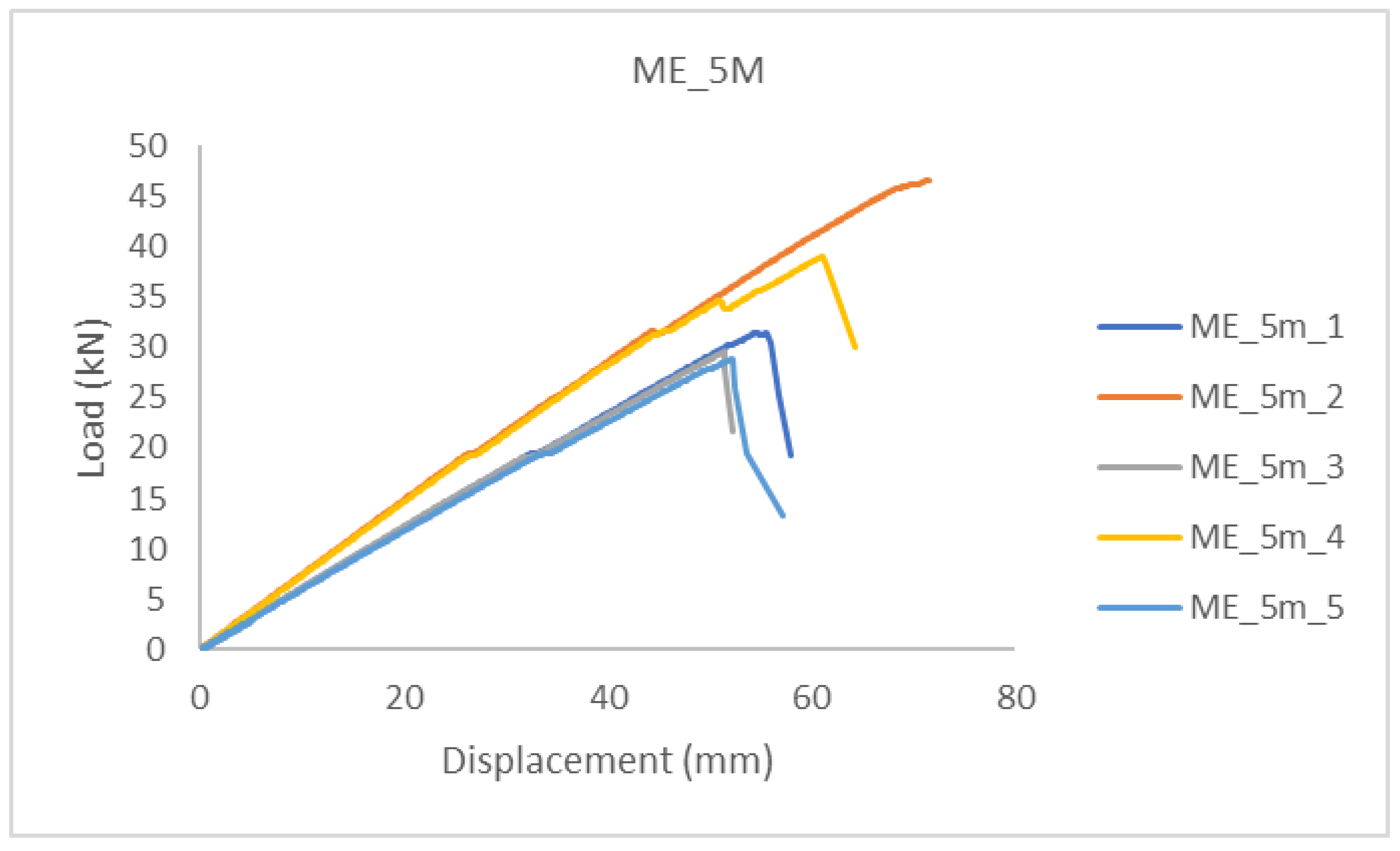
| Average | 35.10 | 58.19 | 9.93 |
| Standard deviation | 7.60 | 8.35 | 0.59 |
| Variation coefficient | 21.65% | 14.36% | 5.99% |
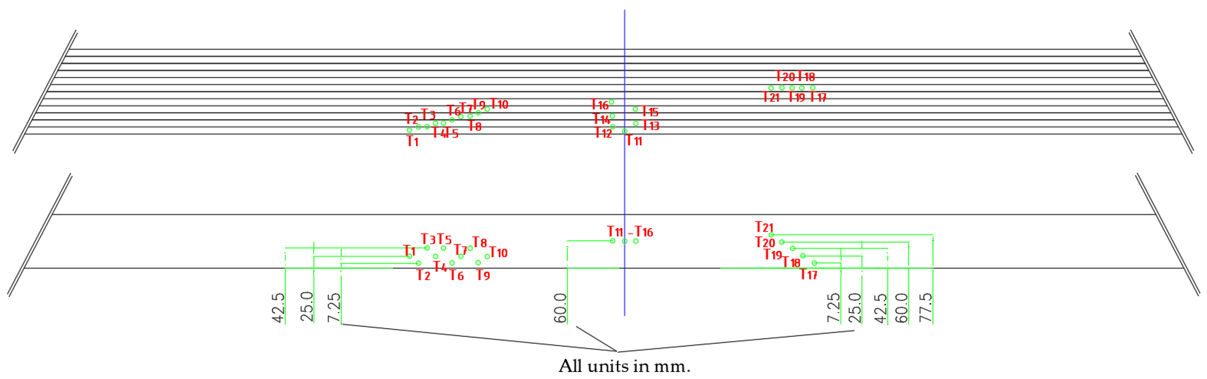
| Measuring Points | Position |
|---|---|
| 1, 11 | mid-height of the 1st lamella |
| 2, 3, 12 | bondline—1st and 2nd lamellae |
| 4, 5, 13 | mid-height of the 2nd lamella |
| 6 | bondline—2nd and 3rd lamellae |
| 7, 8, 14 | mid-height of the 3rd lamella |
| 9 | bondline—3rd and 4th lamellae |
| 10, 15 | mid-height of the 4th lamella |
| 16 | mid-height of the 5th lamella |
| Thermocouples | Depth Installation—Distance from the Exposed Side |
|---|---|
| 2, 6, 9 and 17 | 7.25 mm |
| 1, 4, 7, 10 and 18 | 25 mm |
| 3, 5, 8 and 19 | 42.5 mm |
| 11–16 m, and 20 | 60 mm |
| 21 | 77.5 mm |
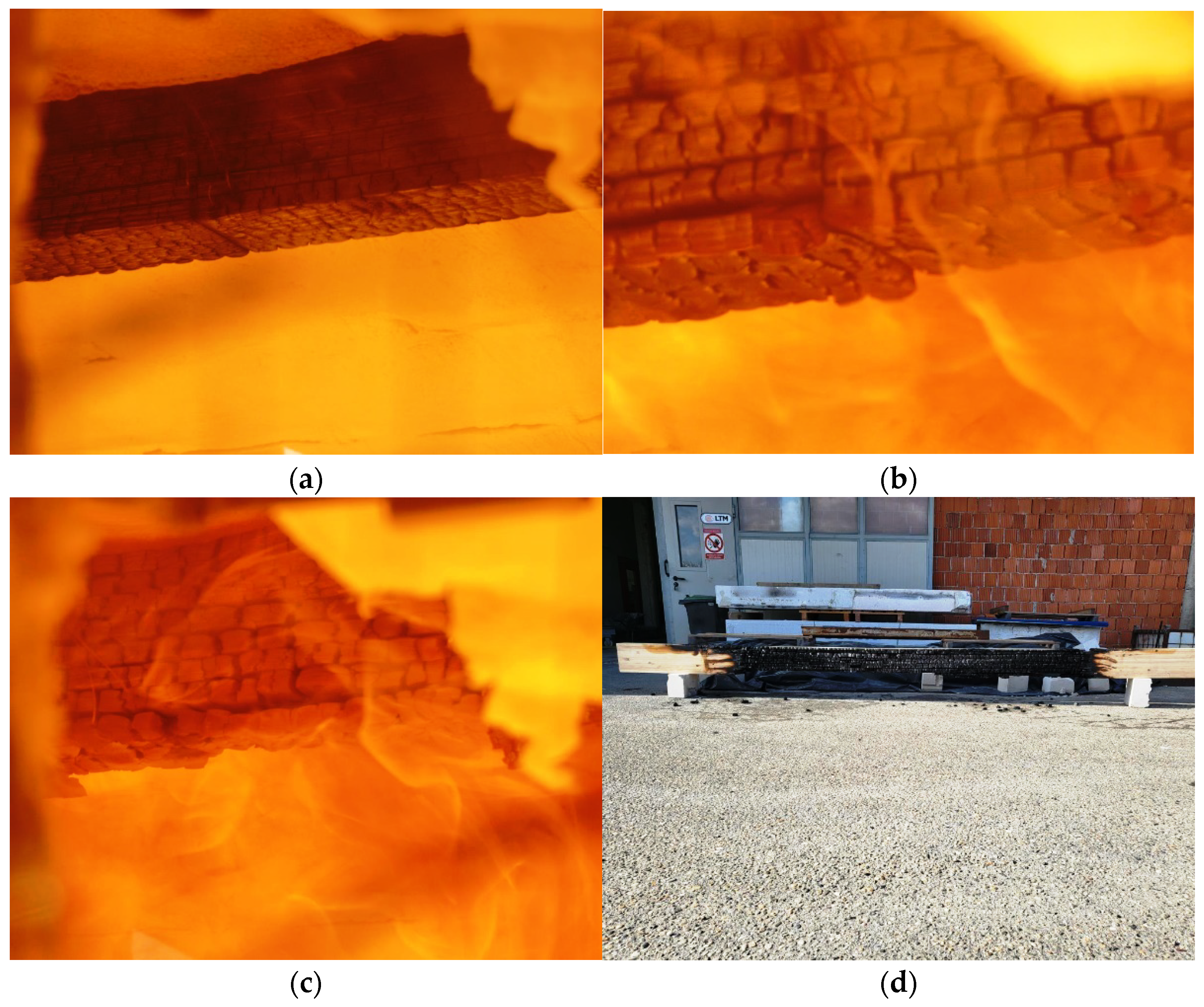
| Time (min:s) | Side (Exposed or Non-Exposed) | Observation |
|---|---|---|
| 00:00 | Start of the test | |
| 05:10 | EX | The surface of the sample is completely charred, and flame occurs |
| 12:20 | EX | The lamellae at the bottom of the sample begin to separate—a gap of 3–5 mm. |
| 27:10 | EX | Fallen thermocouples were placed on the outside of the first lamella due to its combustion. |
| 31:20 | EX | Part of the lamellae of the first layer falls off. |
| 36:10 | EX | The next layer of lamellae in the middle of the sample is also separated. |
| 42:20 | NON-EX | A flame comes out on both sides of the sample between it and the insulation. The sample also burned outside the firebox area. |
| 42:30 | The end of the test. |
| Time (min:s) | Side (Exposed or Non-Exposed) | Observation |
|---|---|---|
| 00:00 | Start of the test | |
| 00:50 | EX | The surface of the sample started to turn black (intumescent paint reaction). |
| 01:30 | EX | The intumescent paint completely blackened and began to swell. |
| 14:20 | EX | A visible opening in the layer of intumescent paint cover. |
| 15:30 | EX | A flame appears over the entire exposed surface of the sample. |
| 17:10 | NON-EX | Smoke comes out of the elliptical openings at the end of the beam. |
| 35:20 | EX | Parts of the swollen intumescent paint are falling off—most visible at the supports of the exposed beam |
| 40:15 | EX | Delamination is visible in the middle of the sample. |
| 45:10 | The end of the test. |
| Time (min:s) | Side (Exposed or Non-Exposed) | Observation |
|---|---|---|
| 00:00 | Start of the test | |
| 00:50 | EX | The surface of the sample started to turn black (intumescent paint reaction). |
| 01:30 | EX | The intumescent paint completely blackened and began to swell. |
| 14:50 | EX | A visible opening in the layer of intumescent paint cover. |
| 16:50 | EX | A flame appears over the entire exposed surface of the sample. |
| 17:10 | NON-EX | Smoke comes out of the elliptical openings at the end of the beam. |
| 23:30 | EX | Parts of the swollen intumescent paint are falling off—most visible at the supports of the exposed beam |
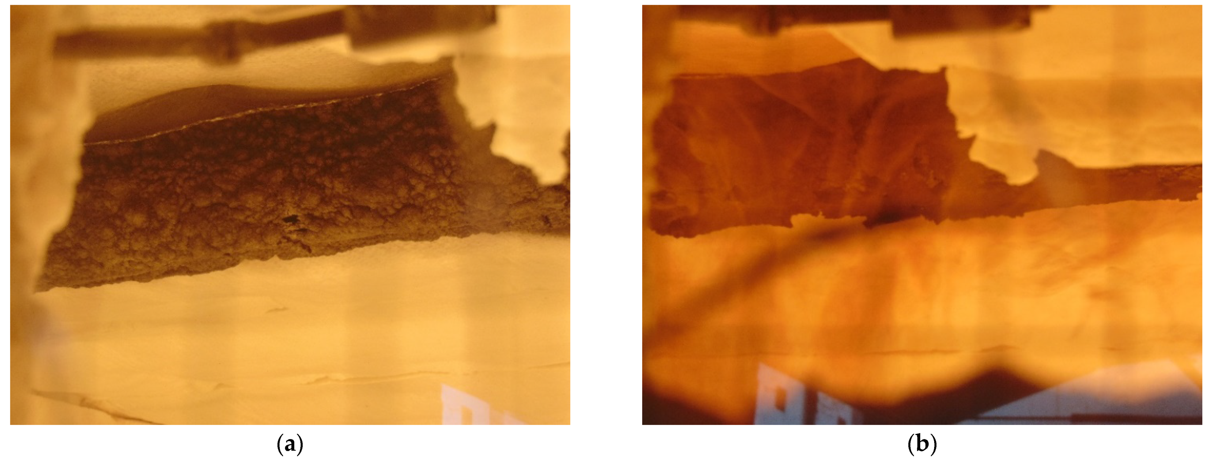
| 39:50 | EX | Mineral wool falling off and delamination are visible in the middle of the sample. |
| 44:20 | The end of the test. |
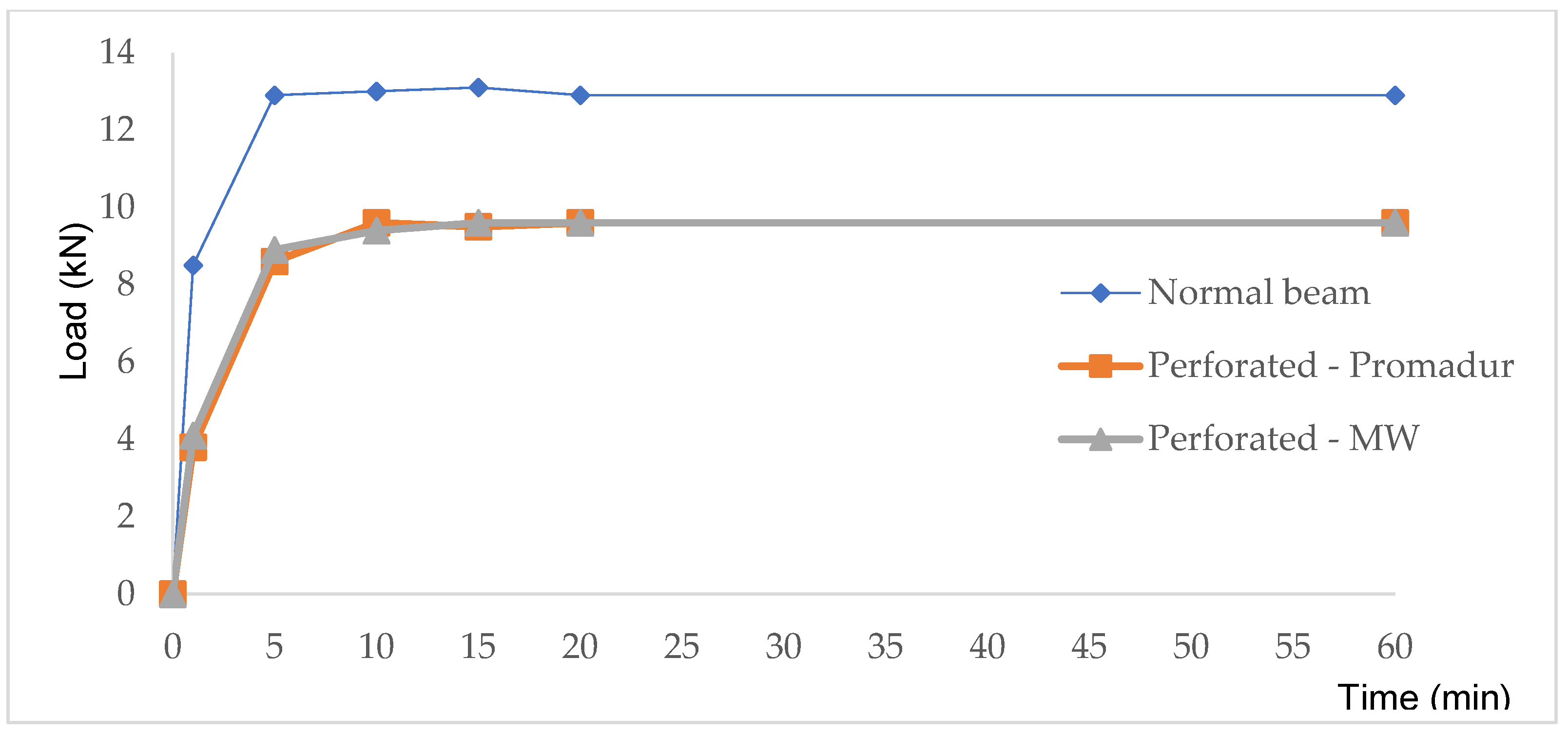
| Sample | Deflection Rate—dD/dt Limit (mm/min) | Final Deflection—D1 (mm) | Test Stop (min) |
|---|---|---|---|
| Normal beam | 7.1 | 63.6 | 43. |
| Hollow-Promadur | 10.7 | 87.4 | 46. |
| Hollow-MW | 15.9 | 88.2. | 45. |
Publisher’s Note: MDPI stays neutral with regard to jurisdictional claims in published maps and institutional affiliations. |
© 2022 by the authors. Licensee MDPI, Basel, Switzerland. This article is an open access article distributed under the terms and conditions of the Creative Commons Attribution (CC BY) license (https://creativecommons.org/licenses/by/4.0/).
Share and Cite
Perković, N.; Rajčić, V. Mechanical and Fire Performance of Innovative Hollow Glue-Laminated Timber Beams. Polymers 2022, 14, 3381. https://doi.org/10.3390/polym14163381
Perković N, Rajčić V. Mechanical and Fire Performance of Innovative Hollow Glue-Laminated Timber Beams. Polymers. 2022; 14(16):3381. https://doi.org/10.3390/polym14163381
Chicago/Turabian StylePerković, Nikola, and Vlatka Rajčić. 2022. "Mechanical and Fire Performance of Innovative Hollow Glue-Laminated Timber Beams" Polymers 14, no. 16: 3381. https://doi.org/10.3390/polym14163381
APA StylePerković, N., & Rajčić, V. (2022). Mechanical and Fire Performance of Innovative Hollow Glue-Laminated Timber Beams. Polymers, 14(16), 3381. https://doi.org/10.3390/polym14163381