
Sensitive Non-Enzymatic Glucose Electrochemical Sensor Based on Electrochemically Synthesized PANI/Bimetallic Oxide Composite

 ,
,  ,
,  ,
,  ,
,  and
and 
Abstract
:1. Introduction
2. Materials and Methods
2.1. Reagents
2.2. Apparatus
2.3. Experimental
2.3.1. Synthesis of PANI
2.3.2. Deposition of MnO and BaO on the PANI Support
2.3.3. Characterization Technique
2.3.4. Application for Glucose Sensing
3. Results and Discussion
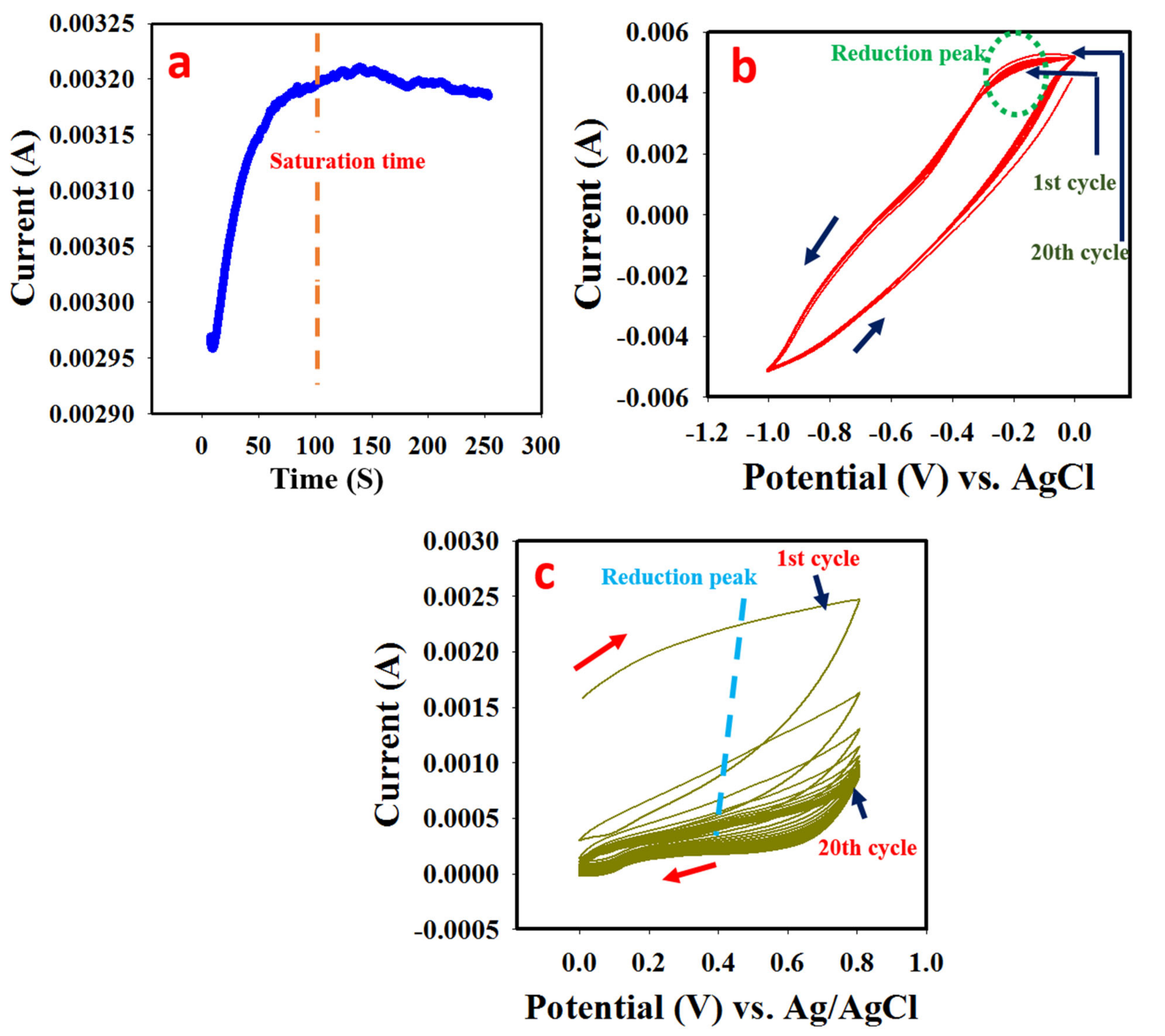
3.1. Synthesis of PANI
3.2. Electrodeposition of MnO
3.3. Electrodeposition of BaO
3.4. Morphological Studies
3.5. Functionalities and Elemental Analysis
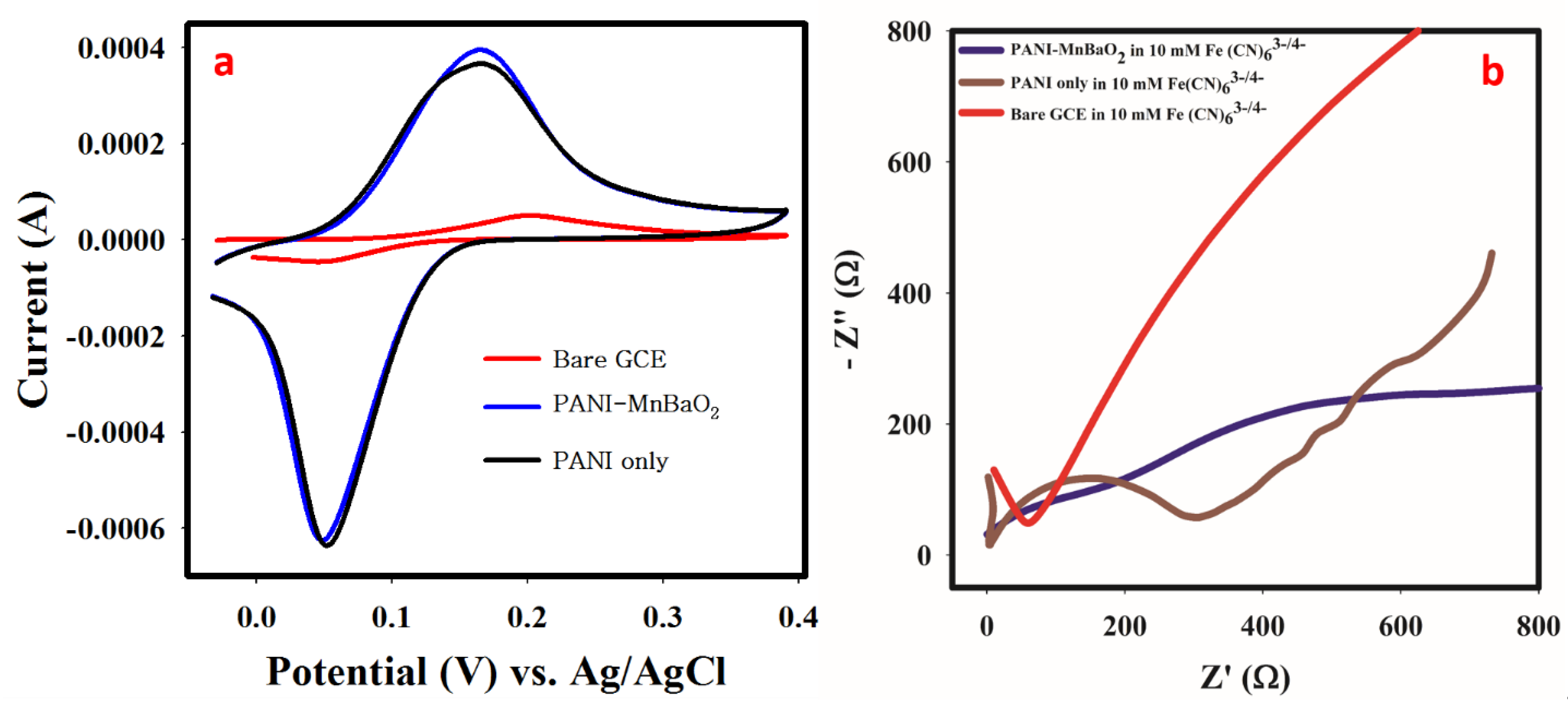
3.6. Material Characterization with Cyclic Voltammetry and EIS
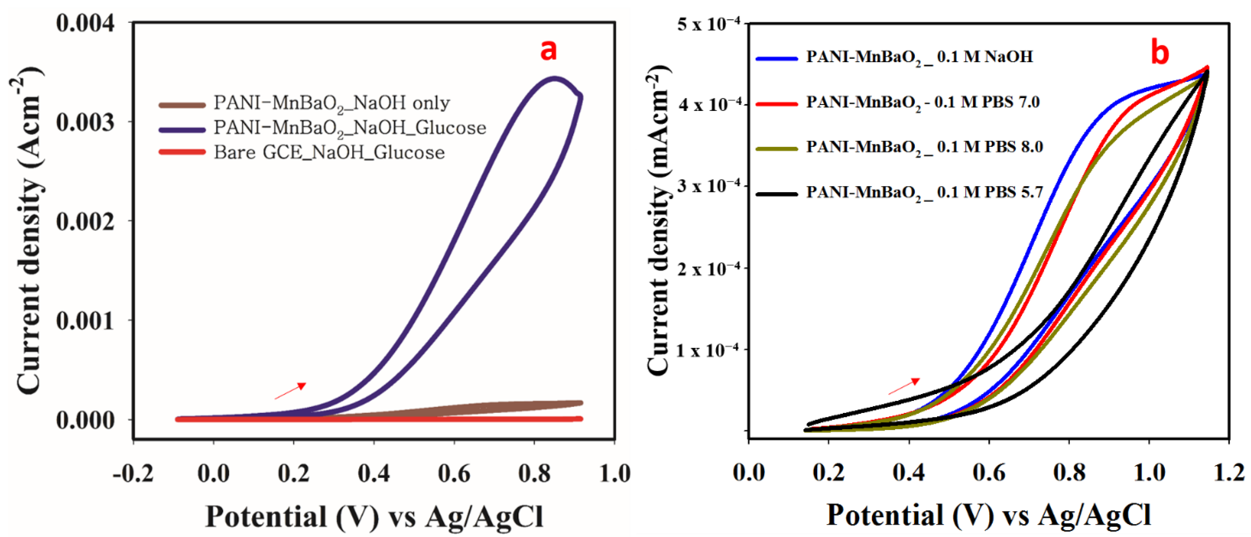
3.7. Electrochemical Response to Glucose
3.7.1. Control Study and Optimization
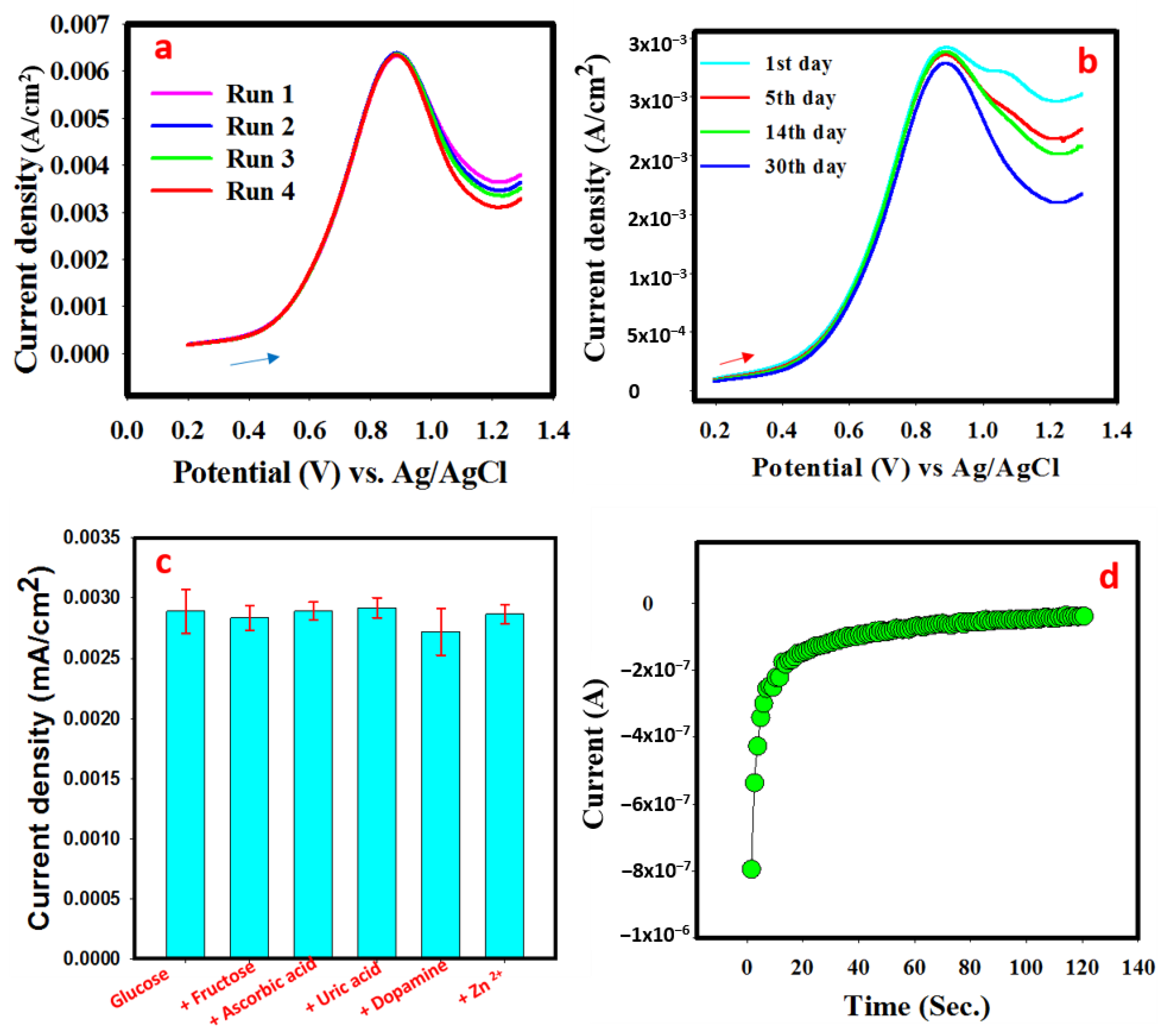
3.7.2. Calibration Curve, Scan Rate, and Response Stability
3.7.3. Real Sample Analysis
3.8. Comparison with Earlier Reported Glucose Electrochemical Sensor
4. Conclusions
Supplementary Materials
Author Contributions
Funding
Institutional Review Board Statement
Informed Consent Statement
Data Availability Statement
Conflicts of Interest
References
- Monami, M.; Dicembrini, I.; Nardini, C.; Fiordelli, I.; Mannucci, E. Glucagon-like peptide-1 receptor agonists and pancreatitis: A meta-analysis of randomized clinical trials. Diabetes Res. Clin. Pract. 2014, 103, 269–275. [Google Scholar] [CrossRef]
- Hindmarsh, P.C.; Geertsma, K. Chapter 19—Glucose and Cortisol. In Congenit Adrenal Hyperplasia; Academic Press: Cambridge, MA, USA, 2017; pp. 219–230. [Google Scholar] [CrossRef]
- Baura, G. (Ed.) Chapter 20—Artificial pancreas. In Medical Device Technologies: A Systems Based Overview Using Engineering Standards, 2nd ed.; Academic Press: Cambridge, MA, USA, 2021; pp. 503–537. [Google Scholar] [CrossRef]
- Arnone, D.; Chabot, C.; Heba, A.-C.; Kökten, T.; Caron, B.; Hansmannel, F.; Dreumont, N.; Ananthakrishnan, A.N.; Quilliot, D.; Peyrin-Biroulet, L. Sugars and Gastrointestinal Health. Clin. Gastroenterol. Hepatol. 2021, in press. [Google Scholar] [CrossRef] [PubMed]
- World Health Organization. World Health Statistics; World Health Organization: Geneva, Switzerland, 2012. [Google Scholar]
- Centers for Disease Control and Prevention. National Diabetes Fact Sheet: National Estimates and General Information on Diabetes and Prediabetes in the United States; US. Department of Health and Human Services: Atlanta, GA, USA, 2012.
- Wei, M.; Qiao, Y.; Zhao, H.; Liang, J.; Li, T.; Luo, Y.; Lu, S.; Shi, X.; Lu, W.; Sun, X. Electrochemical non-enzymatic glucose sensors: Recent progress and perspectives. Chem. Commun. 2020, 56, 14553–14569. [Google Scholar] [CrossRef] [PubMed]
- Hwang, D.-W.; Lee, S.; Seo, M.; Chung, T.D. Recent advances in electrochemical non-enzymatic glucose sensors—A review. Anal. Chim. Acta 2018, 1033, 1–34. [Google Scholar] [CrossRef] [PubMed]
- Jia, H.; Shang, N.; Feng, Y.; Ye, H.; Zhao, J.; Wang, H.; Wang, C.; Zhang, Y. Facile preparation of Ni nanoparticle embedded on mesoporous carbon nanorods for non-enzymatic glucose detection. J. Colloid Interface Sci. 2021, 583, 310–320. [Google Scholar] [CrossRef]
- Zhang, L.; Zhou, C.; Luo, J.; Long, Y.; Wang, C.; Yu, T.; Xiao, D. A polyaniline microtube platform for direct electron transfer of glucose oxidase and biosensing applications. J. Mater. Chem. B 2015, 3, 1116–1124. [Google Scholar] [CrossRef] [PubMed]
- Tang, W.; Li, L.; Zeng, X. A glucose biosensor based on the synergistic action of nanometer-sized TiO2 and polyaniline. Talanta 2015, 131, 417–423. [Google Scholar] [CrossRef] [PubMed]
- Lakhdari, D.; Guittoum, A.; Benbrahim, N.; Belgherbi, O.; Berkani, M.; Vasseghian, Y.; Lakhdari, N. A novel non-enzymatic glucose sensor based on NiFe(NPs)–polyaniline hybrid materials. Food Chem. Toxicol. 2021, 151, 112099. [Google Scholar] [CrossRef] [PubMed]
- Liu, T.; Guo, Y.; Zhang, Z.; Miao, Z.; Zhang, X.; Su, Z. Fabrication of hollow CuO/PANI hybrid nanofibers for non-enzymatic electrochemical detection of H2O2 and glucose. Sens. Actuators B Chem. 2019, 286, 370–376. [Google Scholar] [CrossRef]
- Varghese, E.V.; Saidu, F.K.; Schwandt, C.; Thomas, G.; Joseph, A. Non-Enzymatic Electrochemical Biosensing of Glucose Using Nanocomposites of Polyaniline Nanofibers and Silver. ChemistrySelect 2022, 7, e202103518. [Google Scholar] [CrossRef]
- Yassin, M.A.; Shrestha, B.K.; Ahmad, R.; Shrestha, S.; Park, C.H.; Kim, C.S. Exfoliated nanosheets of Co3O4 webbed with polyaniline nanofibers: A novel composite electrode material for enzymeless glucose sensing application. J. Ind. Eng. Chem. 2019, 73, 106–117. [Google Scholar] [CrossRef]
- Osuna, V.; Vega-Rios, A.; Zaragoza-Contreras, E.A.; Estrada-Moreno, I.A.; Dominguez, R.B. Progress of Polyaniline Glucose Sensors for Diabetes Mellitus Management Utilizing Enzymatic and Non-Enzymatic Detection. Biosensors 2022, 12, 137. [Google Scholar] [CrossRef]
- Du, X.; Chen, Y.; Dong, W.; Han, B.; Liu, M.; Chen, Q.; Zhou, J. A nanocomposite-based electrochemical sensor for non-enzymatic detection of hydrogen peroxide. Oncotarget 2017, 8, 13039–13047. [Google Scholar] [CrossRef] [PubMed] [Green Version]
- Selvakumar, K.; Kumar, S.S.; Thangamuthu, R.; Kruthika, G.; Murugan, P. Development of shape-engineered α-MnO2 materials as bi-functional catalysts for oxygen evolution reaction and oxygen reduction reaction in alkaline medium. Int. J. Hydrogen Energy 2014, 39, 21024–21036. [Google Scholar] [CrossRef]
- Renukadevi, R.; Sundaram, R.; Kasinathan, K. Barium oxide nanoparticles with robust catalytic, photocatalytic and humidity sensing properties. J. Nanostruct. 2020, 10, 167–176. [Google Scholar] [CrossRef]
- Inamuddin; Kashmery, H.A. Ternary graphene@polyaniline-TiO2 composite for glucose biofuel cell anode application. Int. J. Hydrogen Energy 2019, 44, 22173–22180. [Google Scholar] [CrossRef]
- Adeosun, W.A.; Asiri, A.M.; Marwani, H.M. Sensitive determination of 2-nitrophenol using electrochemically deposited polymethyl red film for healthcare and environmental safety. Synth. Met. 2020, 261, 116321. [Google Scholar] [CrossRef]
- Yoshida, T.; Komatsu, D.; Shimokawa, N.; Minoura, H. Mechanism of cathodic electrodeposition of zinc oxide thin films from aqueous zinc nitrate baths. Thin Solid Films 2004, 451–452, 166–169. [Google Scholar] [CrossRef]
- Prasad, B.E.; Kamath, P.V.; Ranganath, S. Electrodeposition of ZnO coatings from aqueous Zn(NO3)2 baths: Effect of Zn concentration, deposition temperature, and time on orientation. J. Solid State Electrochem. 2012, 16, 3715–3722. [Google Scholar] [CrossRef]
- Cruickshank, A.C.; Tay, S.E.R.; Illy, B.N.; Da Campo, R.; Schumann, S.; Jones, T.S.; Heutz, S.; McLachlan, M.A.; McComb, D.W.; Riley, D.J.; et al. Electrodeposition of ZnO Nanostructures on Molecular Thin Films. Chem. Mater. 2011, 23, 3863–3870. [Google Scholar] [CrossRef]
- Kondawar, S.B.; Deshpande, M.D.; Agrawal, S.P. Transport Properties of Conductive Polyaniline Nanocomposites Based on Carbon Nanotubes. Int. J. Compos. Mater. 2012, 2, 32–36. [Google Scholar] [CrossRef] [Green Version]
- Shadi, L.; Karimi, M.; Entezami, A.A.; Safa, K.D. A facile synthesis of polyaniline/polyethylene glycol/polyaniline terpolymers: Preparation of electrospun conducting nanofibers by blending of the terpolymers with polycaprolactone. Polym. Bull. 2013, 70, 3529–3545. [Google Scholar] [CrossRef]
- Shaikh, S.F.; Shaikh, F.F.; Shaikh, A.V.; Ubaidullah, M.; Al-Enizi, A.M.; Pathan, H.M. Electrodeposited more-hydrophilic nano-nest polyaniline electrodes for supercapacitor application. J. Phys. Chem. Solids 2020, 149, 109774. [Google Scholar] [CrossRef]
- Haque, S.U.; Nasar, A.; Inamuddin; Asiri, A.M. Preparation and characterization of a bioanode (GC/MnO2/PSS/Gph/Frt/GOx) for biofuel cell application. Int. J. Hydrogen Energy 2019, 44, 7308–7319. [Google Scholar] [CrossRef]
- Ahmad, N.; Wahab, R.; Alam, M. Facile Growth of Barium Oxide Nanorods: Structural and Optical Properties. J. Nanosci. Nanotechnol. 2014, 14, 5342–5346. [Google Scholar] [CrossRef]
- Ghanei-Motlagh, M.; Taher, M.A.; Fayazi, M.; Baghayeri, M.; Hosseinifar, A. Non-Enzymatic Amperometric Sensing of Hydrogen Peroxide Based on Vanadium Pentoxide Nanostructures. J. Electrochem. Soc. 2019, 166, B367–B372. [Google Scholar] [CrossRef]
- Asiri, A.M.; Adeosun, W.A.; Marwani, H.M. Electrocatalytic reduction of 2, 6-dinitrophenol on polycongo red decorated glassy carbon electrode for sensing application. J. Environ. Chem. Eng. 2020, 8, 104378. [Google Scholar] [CrossRef]
- Goseer, D.K. Cyclic Voltametry-Simulation and Analysis of Reaction; VCH: New York, NY, USA, 1993. [Google Scholar]
- Fang, L.; Zhu, Q.; Cai, Y.; Liang, B.; Ye, X. 3D porous structured polyaniline/reduced graphene oxide/copper oxide decorated electrode for high performance nonenzymatic glucose detection. J. Electroanal. Chem. 2019, 841, 1–9. [Google Scholar] [CrossRef]
- Yang, J.; Lin, Q.; Yin, W.; Jiang, T.; Zhao, D.; Jiang, L. A novel nonenzymatic glucose sensor based on functionalized PDDA-graphene/CuO nanocomposites. Sens. Actuators B Chem. 2017, 253, 1087–1095. [Google Scholar] [CrossRef]
- Xu, M.; Song, Y.; Ye, Y.; Gong, C.; Shen, Y.; Wang, L.; Wang, L. A novel flexible electrochemical glucose sensor based on gold nanoparticles/polyaniline arrays/carbon cloth electrode. Sens. Actuators B Chem. 2017, 252, 1187–1193. [Google Scholar] [CrossRef]
- Muthusankar, E.; Ragupathy, D. Graphene/Poly(aniline-co-diphenylamine) nanohybrid for ultrasensitive electrochemical glucose sensor. Nano-Struct. Nano-Objects 2019, 20, 100390. [Google Scholar] [CrossRef]
- Ghanbari, K.; Babaei, Z. Fabrication and characterization of non-enzymatic glucose sensor based on ternary NiO/CuO/polyaniline nanocomposite. Anal. Biochem. 2016, 498, 37–46. [Google Scholar] [CrossRef] [PubMed]
- Bilal, S.; Ullah, W.; Shah, A.-U.A. Polyaniline@CuNi nanocomposite: A highly selective, stable and efficient electrode material for binder free non-enzymatic glucose sensor. Electrochim. Acta 2018, 284, 382–391. [Google Scholar] [CrossRef]
- Lopa, N.S.; Rahman, M.; Jang, H.; Sutradhar, S.C.; Ahmed, F.; Ryu, T.; Kim, W. A glassy carbon electrode modified with poly(2,4-dinitrophenylhydrazine) for simultaneous detection of dihydroxybenzene isomers. Mikrochim. Acta 2017, 185, 23. [Google Scholar] [CrossRef] [PubMed]
- Chen, S.; Liu, D.; Song, N.; Wang, C.; Lu, X. Promoting non-enzymatic electrochemical sensing performance toward glucose by the integration of conducting polypyrrole with metal-organic framework. Compos. Commun. 2022, 30, 101074. [Google Scholar] [CrossRef]
- Gopal, T.S.; Jeong, S.K.; Alrebdi, T.A.; Pandiaraj, S.; Alodhayb, A.; Muthuramamoorthy, M.; Grace, A.N. MXene-based composite electrodes for efficient electrochemical sensing of glucose by non-enzymatic method. Mater. Today Chem. 2022, 24, 100891. [Google Scholar] [CrossRef]


| Sample | Replicate Number | Spiked Concentration (mM) | Detected Concentration (mM) | Bias | RSD (%) | Recovery (%) |
|---|---|---|---|---|---|---|
| Human serum Albumin | 3 | 0.5 | 0.38 ± 0.02 | −0.12 | 5.2 | 76 |
| 3 | 1 | 0.85 ± 0.019 | −0.15 | 2.2 | 85 | |
| 3 | 2 | 2.2 ± 0.07 | 0.2 | 3.18 | 110 |
| Electrode Materials | LR (mM) | FDR (mM) | LOD (µM) | Sensitivity (µAmM−1 cm−2) | Ref |
|---|---|---|---|---|---|
| PANI/GO/CuO | 0–13 | 0–20 | 1.5 | 1252 | [33] |
| PDDA-graphene/CuO | 0.04–4 | 0.04–4 | 0.2 | 4982.2 | [34] |
| Au NPs/PANI | 0.01–10 | 0.01–10 | 3.05 | 150 | [35] |
| Graphene/polyaniline-co-diphenylamine | 0.001–1 | 0.001–1 | 0.1 | 500 | [36] |
| CuO/NiO/PANI | 0.02–2.5 | 0.02–2.5 | 2.0 | - | [37] |
| PANI/CuNi | 1–7 | 1–10 | 0.2 | 1030 | [38] |
| Ni2(dihydroxyterephtalic acid) MOFs | 0.04–0.8 | 0.04–6 | 1.46 | 40.95 | [39] |
| Polypyrrole-MOFs | 0.02–0.5 | 0.02–3 | 1.13 | 1805 | [40] |
| MXene-Cu2O | 0.01–30 | - | 2.83 | 11.061 | [41] |
| PANi/MnBaO2/GCE | 0.05–1.6 | 0.05–10 | 0.06 | 128 | This Study |
Publisher’s Note: MDPI stays neutral with regard to jurisdictional claims in published maps and institutional affiliations. |
© 2022 by the authors. Licensee MDPI, Basel, Switzerland. This article is an open access article distributed under the terms and conditions of the Creative Commons Attribution (CC BY) license (https://creativecommons.org/licenses/by/4.0/).
Share and Cite
Khan, A.; Khan, A.A.P.; Marwani, H.M.; Alotaibi, M.M.; Asiri, A.M.; Manikandan, A.; Siengchin, S.; Rangappa, S.M. Sensitive Non-Enzymatic Glucose Electrochemical Sensor Based on Electrochemically Synthesized PANI/Bimetallic Oxide Composite. Polymers 2022, 14, 3047. https://doi.org/10.3390/polym14153047
Khan A, Khan AAP, Marwani HM, Alotaibi MM, Asiri AM, Manikandan A, Siengchin S, Rangappa SM. Sensitive Non-Enzymatic Glucose Electrochemical Sensor Based on Electrochemically Synthesized PANI/Bimetallic Oxide Composite. Polymers. 2022; 14(15):3047. https://doi.org/10.3390/polym14153047
Chicago/Turabian StyleKhan, Anish, Aftab Aslam Parwaz Khan, Hadi M. Marwani, Maha Moteb Alotaibi, Abdullah M. Asiri, Ayyar Manikandan, Suchart Siengchin, and Sanjay Mavinkere Rangappa. 2022. "Sensitive Non-Enzymatic Glucose Electrochemical Sensor Based on Electrochemically Synthesized PANI/Bimetallic Oxide Composite" Polymers 14, no. 15: 3047. https://doi.org/10.3390/polym14153047
APA StyleKhan, A., Khan, A. A. P., Marwani, H. M., Alotaibi, M. M., Asiri, A. M., Manikandan, A., Siengchin, S., & Rangappa, S. M. (2022). Sensitive Non-Enzymatic Glucose Electrochemical Sensor Based on Electrochemically Synthesized PANI/Bimetallic Oxide Composite. Polymers, 14(15), 3047. https://doi.org/10.3390/polym14153047