The Role of Roller Rotation Pattern in the Spreading Process of Polymer/Short-Fiber Composite Powder in Selective Laser Sintering


Abstract
:1. Introduction
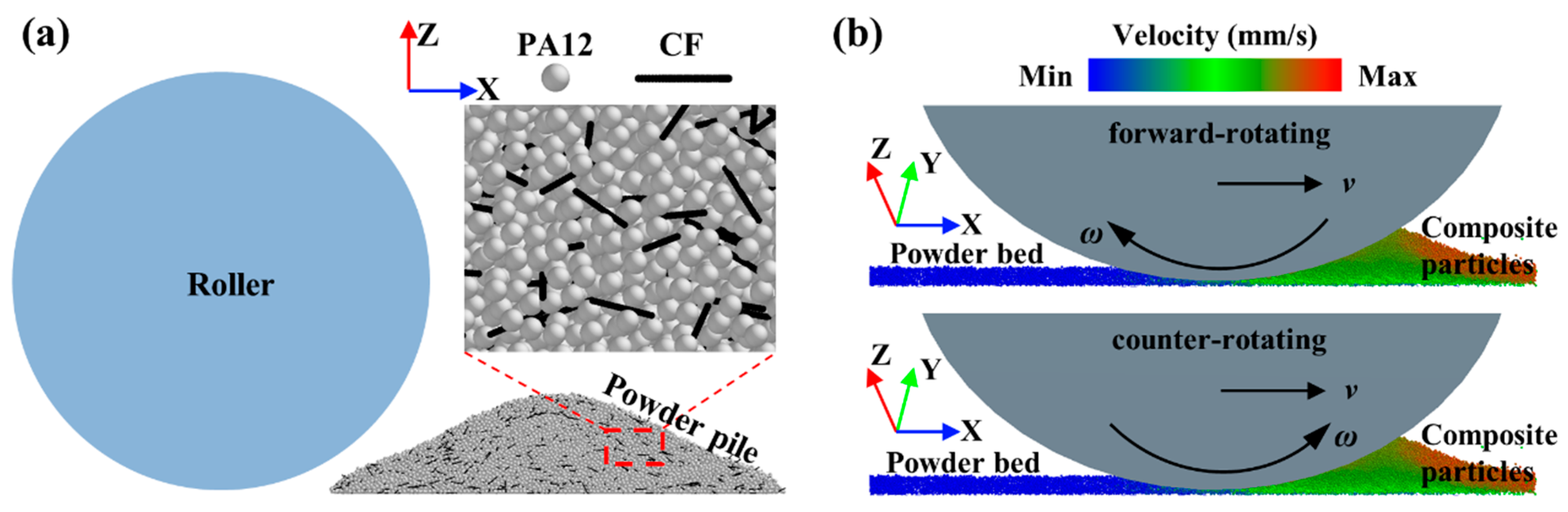
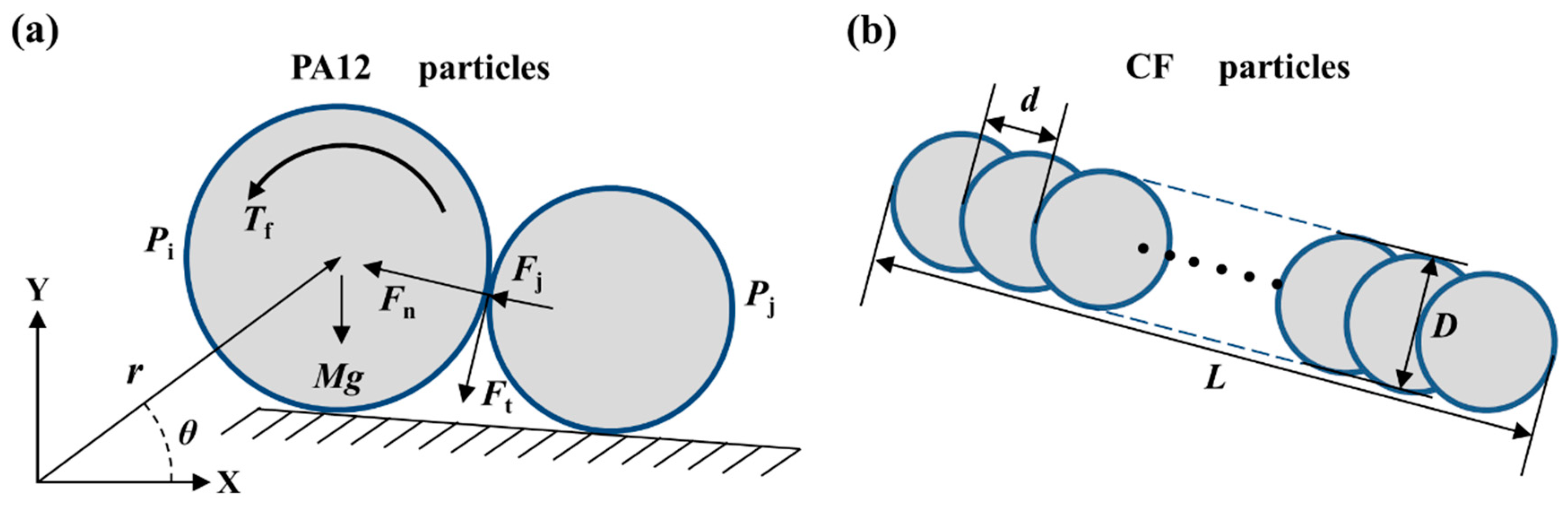
2. Numerical Model
2.1. Governing Equations
2.2. Time Step
2.3. Simulation Parameters and Conditions

| Parameters | Symbols | Values | ||
|---|---|---|---|---|
| PA12 | CF | PA12-CF | ||
| Density | ρ (g/cm3) | 1.76 | 1.01 | - |
| Young′s modulus [35,36] | E (Gpa) | 230 | 2.3 | - |
| Poisson′s ratio [35,36] | γ | 0.3 | 0.4 | - |
| Sliding friction coefficient [13] | µs | 0.45 | 0.3 | 0.4 |
| Rolling friction coefficient [13] | µr | 0.01 | 0.01 | 0.01 |
| Restitution coefficient [13] | e | 0.5 | 0.8 | - |
| Surface energy density [35,36] | W (mJ/m2) | 32 | 38 | - |
| Spreading speed | v (mm/s) | 50–150 | ||
| Rotation speed | ω (rad/s) | 0–4.8π | ||
| Layer thickness | h (µm) | 100 | ||
| Roller diameter | Dr (mm) | 10 | ||
| Particle size distribution | λ1 (µm) | 30–70 | ||
| Fiber length distribution | λ2 (µm) | 40–180 | ||
| Fiber diameter | Df (µm) | 10 | ||
3. Results and Discussion
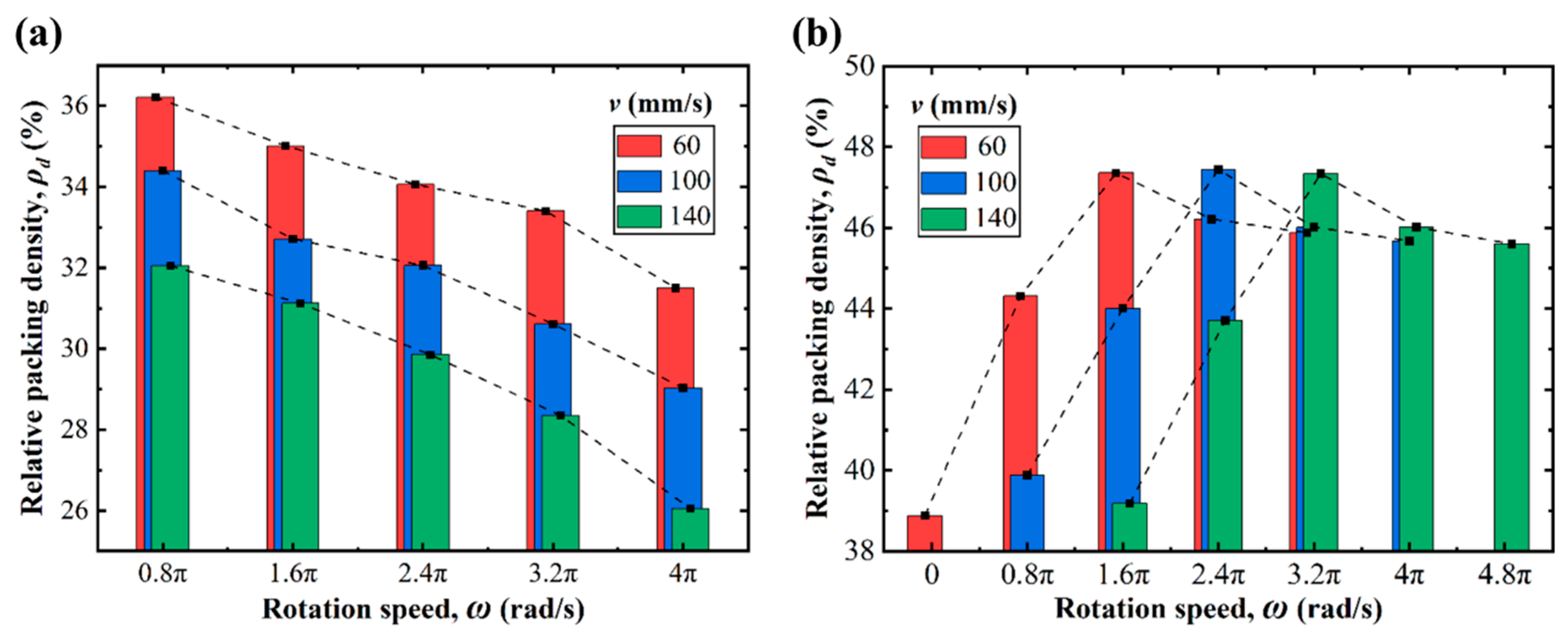
3.1. Packing Quality of Powder Bed
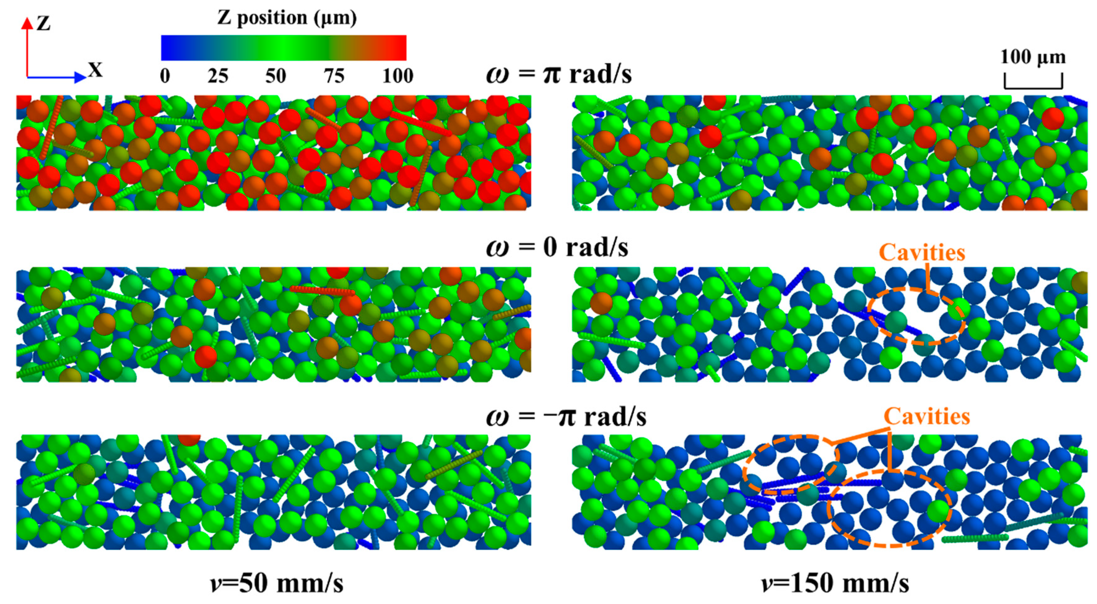
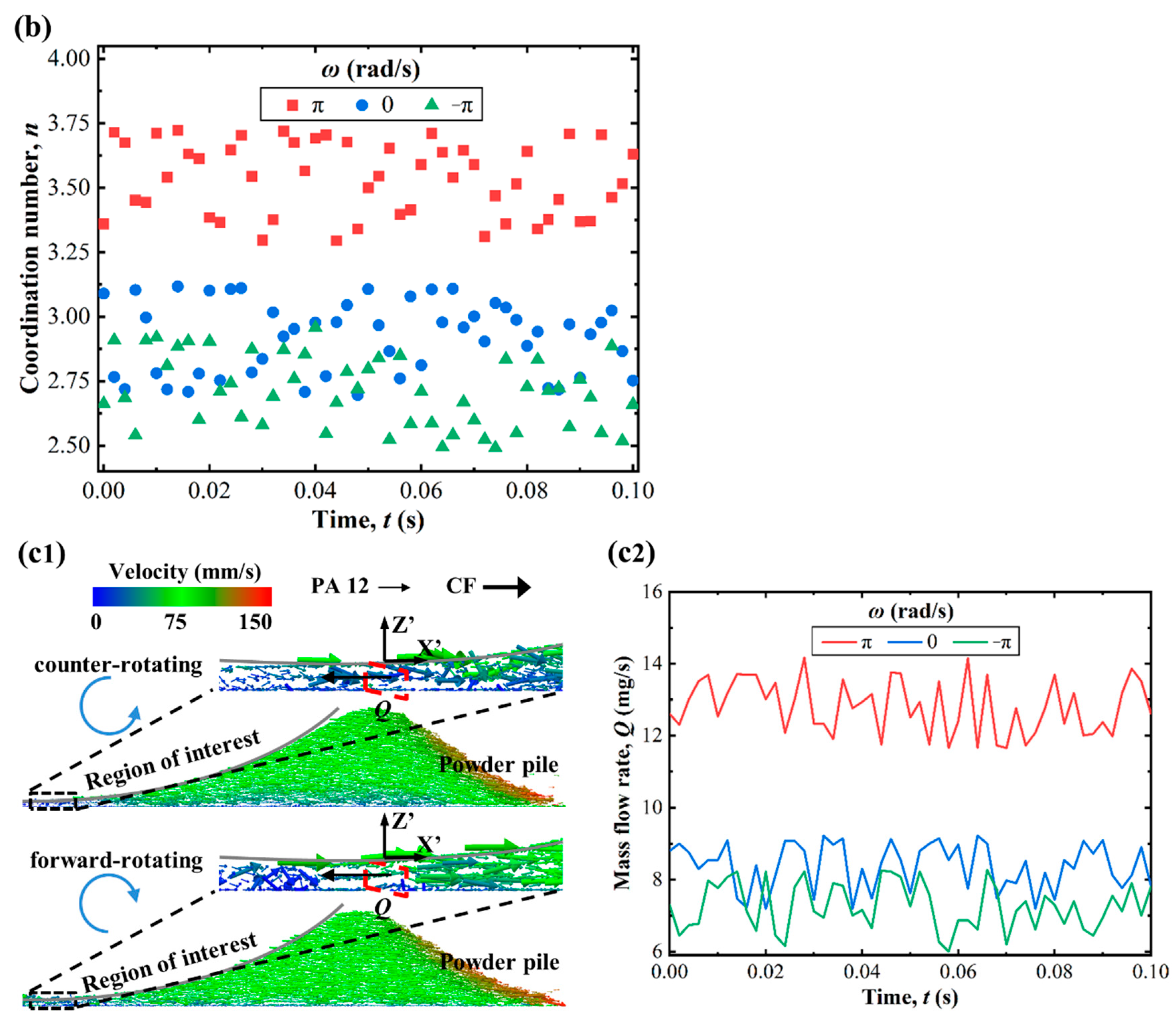
3.2. Kinetic Comparison of Composite Powder Particles in Forward-Rotating and Counter-Rotating Patterns
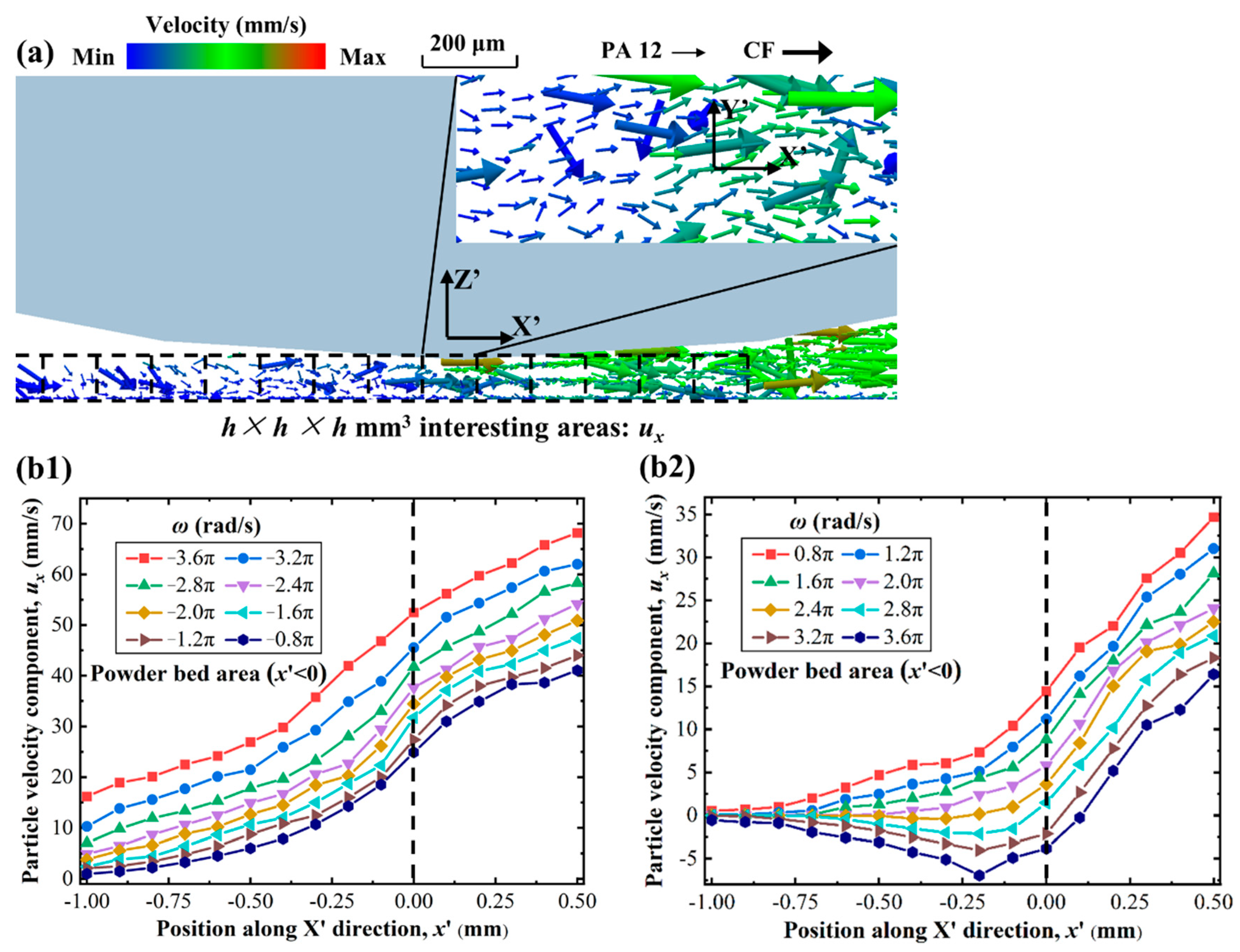
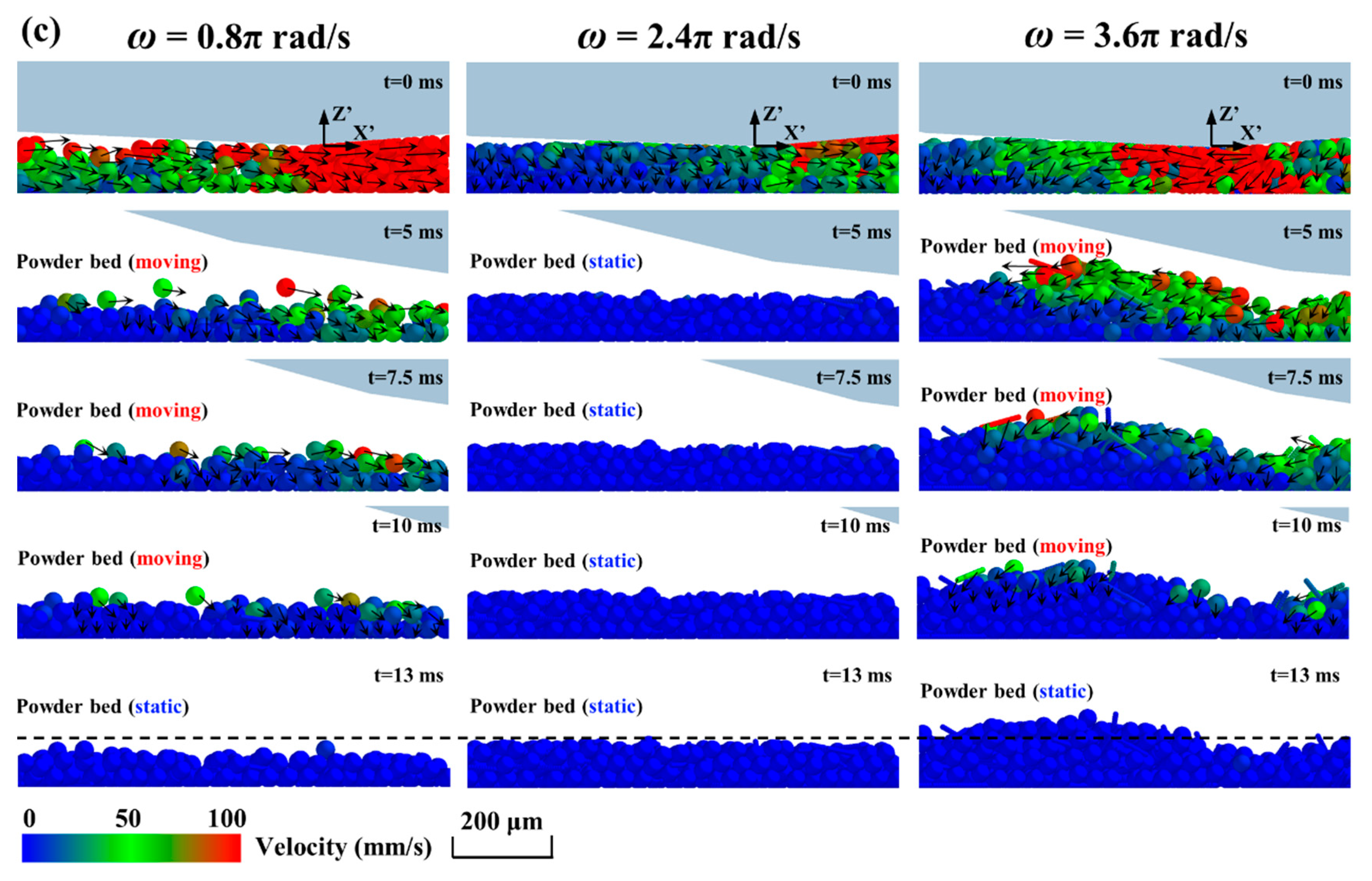
3.3. Effects of Rotation Speed
4. Conclusions
Author Contributions
Funding
Institutional Review Board Statement
Informed Consent Statement
Data Availability Statement
Acknowledgments
Conflicts of Interest
References
- Baba, M.N. Flatwise to Upright Build Orientations under Three-Point Bending Test of Nylon 12 (PA12) Additively Manufactured by SLS. Polymers 2022, 14, 1026. [Google Scholar] [CrossRef] [PubMed]
- Gueche, Y.A.; Sanchez-Ballester, N.M.; Bataille, B.; Aubert, A.; Rossi, J.C.; Soulairol, I. Investigating the Potential Plasticizing Effect of Di-Carboxylic Acids for the Manufacturing of Solid Oral Forms with Copovidone and Ibuprofen by Selective Laser Sintering. Polymers 2021, 13, 3282. [Google Scholar] [CrossRef] [PubMed]
- Loganathan, T.M.; Hameed Sultan, M.T.; Jawaid, M.; Ahsan, Q.; Naveen, J.; Shah, A.U.M.; Abu Talib, A.R.; Basri, A.A. Physical, Mechanical, and Morphological Properties of Hybrid Cyrtostachys renda/Kenaf Fiber Reinforced with Multi-Walled Carbon Nanotubes (MWCNT)-Phenolic Composites. Polymers 2021, 13, 3448. [Google Scholar] [CrossRef] [PubMed]
- Franco-Urquiza, E.A.; Saleme-Osornio, R.S.; Ramirez-Aguilar, R. Mechanical Properties of Hybrid Carbonized Plant Fibers Reinforced Bio-Based Epoxy Laminates. Polymers 2021, 13, 3435. [Google Scholar] [CrossRef]
- Zhu, W.; Yan, C.; Shi, Y.; Wen, S.; Liu, J.; Wei, Q.; Shi, Y. A novel method based on selective laser sintering for preparing high-performance carbon fibres/polyamide12/epoxy ternary composites. Sci. Rep. 2016, 6, 33780. [Google Scholar] [CrossRef] [Green Version]
- Yan, M.; Tian, X.; Peng, G.; Li, D.; Zhang, X. High temperature rheological behavior and sintering kinetics of CF/PEEK composites during selective laser sintering. Compos. Sci. Technol. 2018, 165, 140–147. [Google Scholar] [CrossRef]
- Cobian, L.; Rueda-Ruiz, M.; Fernandez-Blazquez, J.P.; Martinez, V.; Galvez, F.; Karayagiz, F.; Lück, T.; Segurado, J.; Monclus, M.A. Micromechanical characterization of the material response in a PA12-SLS fabricated lattice structure and its correlation with bulk behavior. Polym. Test. 2022, 110, 107556. [Google Scholar] [CrossRef]
- Peyre, P.; Rouchausse, Y.; Defauchy, D.; Régnier, G. Experimental and numerical analysis of the selective laser sintering (SLS) of PA12 and PEKK semi-crystalline polymers. J. Mater. Process. Technol. 2015, 225, 326–336. [Google Scholar] [CrossRef]
- Schneider, J.; Kumar, S. Multiscale characterization and constitutive parameters identification of polyamide (PA12) processed via selective laser sintering. Polym. Test. 2020, 86, 106357. [Google Scholar] [CrossRef]
- Tran, H.-C.; Lo, Y.-L.; Huang, M.-H. Analysis of Scattering and Absorption Characteristics of Metal Powder Layer for Selective Laser Sintering. IEEE/ASME Trans. Mechatron. 2017, 22, 1807–1817. [Google Scholar] [CrossRef]
- Karapatis, N.; Egger, G. Optimization of Powder Layer Density in Selective Laser Sintering. In Proceedings of the 1999 International Solid Freeform Fabrication Symposium, Austin, TX, USA, 9–11 August 1999; p. 255e264. [Google Scholar]
- Haeri, S.; Wang, Y.; Ghita, O.; Sun, J. Discrete element simulation and experimental study of powder spreading process in additive manufacturing. Powder Technol. 2017, 306, 45–54. [Google Scholar] [CrossRef] [Green Version]
- Chen, H.; Zhu, W.; Tang, H.; Yan, W. Oriented structure of short fiber reinforced polymer composites processed by selective laser sintering: The role of powder-spreading process. Int. J. Mach. Tools Manuf. 2021, 163, 103703. [Google Scholar] [CrossRef]
- Chen, H.; Cheng, T.; Wei, Q.; Yan, W. Dynamics of short fiber/polymer composite particles in paving process of additive manufacturing. Addit. Manuf. 2021, 47, 102246. [Google Scholar] [CrossRef]
- Parandoush, P.; Lin, D. A review on additive manufacturing of polymer-fiber composites. Compos. Struct. 2017, 182, 36–53. [Google Scholar] [CrossRef]
- Wang, L.; Zhou, Z.; Li, E.; Shen, H.; Yu, A. Powder deposition mechanism during powder spreading with different spreader geometries in powder bed fusion additive manufacturing. Powder Technol. 2022, 395, 802–810. [Google Scholar] [CrossRef]
- Chen, H.; Wei, Q.; Wen, S.; Li, Z.; Shi, Y. Flow behavior of powder particles in layering process of selective laser melting: Numerical modeling and experimental verification based on discrete element method. Int. J. Mach. Tools Manuf. 2017, 123, 146–159. [Google Scholar] [CrossRef]
- Wang, L.; Yu, A.; Li, E.; Shen, H.; Zhou, Z. Effects of spreader geometry on powder spreading process in powder bed additive manufacturing. Powder Technol. 2021, 384, 211–222. [Google Scholar] [CrossRef]
- Haeri, S. Optimisation of blade type spreaders for powder bed preparation in Additive Manufacturing using DEM simulations. Powder Technol. 2017, 321, 94–104. [Google Scholar] [CrossRef] [Green Version]
- Nan, W.; Pasha, M.; Bonakdar, T.; Lopez, A.; Zafar, U.; Nadimi, S.; Ghadiri, M. Jamming during particle spreading in additive manufacturing. Powder Technol. 2018, 338, 253–262. [Google Scholar] [CrossRef]
- Nan, W.; Pasha, M.; Ghadiri, M. Numerical simulation of particle flow and segregation during roller spreading process in additive manufacturing. Powder Technol. 2020, 364, 811–821. [Google Scholar] [CrossRef]
- Zhang, J.; Tan, Y.; Xiao, X.; Jiang, S. Comparison of roller-spreading and blade-spreading processes in powder-bed additive manufacturing by DEM simulations. Particuology 2022, 66, 48–58. [Google Scholar] [CrossRef]
- Chen, H.; Chen, Y.; Liu, Y.; Wei, Q.; Shi, Y.; Yan, W. Packing quality of powder layer during counter-rolling-type powder spreading process in additive manufacturing. Int. J. Mach. Tools Manuf. 2020, 153, 103553. [Google Scholar] [CrossRef]
- Meier, C.; Weissbach, R.; Weinberg, J.; Wall, W.A.; Hart, A.J. Critical influences of particle size and adhesion on the powder layer uniformity in metal additive manufacturing. J. Mater. Process. Technol. 2019, 266, 484–501. [Google Scholar] [CrossRef] [Green Version]
- Dadbakhsh, S.; Verbelen, L.; Verkinderen, O.; Strobbe, D.; Van Puyvelde, P.; Kruth, J.-P. Effect of PA12 powder reuse on coalescence behaviour and microstructure of SLS parts. Eur. Polym. J. 2017, 92, 250–262. [Google Scholar] [CrossRef]
- Steuben, J.C.; Iliopoulos, A.P.; Michopoulos, J.G. Discrete element modeling of particle-based additive manufacturing processes. Comput. Methods Appl. Mech. Eng. 2016, 305, 537–561. [Google Scholar] [CrossRef] [Green Version]
- Cundall, P.A.; Strack, O.D. A discrete numerical model for granular assemblies. Geotechnique 1979, 29, 47–65. [Google Scholar] [CrossRef]
- Tsuji, Y.; Tanaka, T.; Ishida, T. Lagrangian numerical simulation of plug flow of cohesionless particles in a horizontal pipe. Powder Technol. 1992, 71, 239–250. [Google Scholar] [CrossRef]
- Barthel, E. Adhesive elastic contacts: JKR and more. J. Phys. D Appl. Phys. 2008, 41, 163001. [Google Scholar] [CrossRef] [Green Version]
- Langston, P.A.; Al-Awamleh, M.A.; Fraige, F.Y.; Asmar, B.N. Distinct element modelling of non-spherical frictionless particle flow. Chem. Eng. Sci. 2004, 59, 425–435. [Google Scholar] [CrossRef]
- Cleary, P.W. A multiscale method for including fine particle effects in DEM models of grinding mills. Miner. Eng. 2015, 84, 88–99. [Google Scholar] [CrossRef]
- Coetzee, C. Calibration of the discrete element method: Strategies for spherical and non-spherical particles. Powder Technol. 2020, 364, 851–878. [Google Scholar] [CrossRef]
- Parteli, E.J.R.; Pöschel, T. Particle-based simulation of powder application in additive manufacturing. Powder Technol. 2016, 288, 96–102. [Google Scholar] [CrossRef]
- Berger, R.; Kloss, C.; Kohlmeyer, A.; Pirker, S. Hybrid parallelization of the LIGGGHTS open-source DEM code. Powder Technol. 2015, 278, 234–247. [Google Scholar] [CrossRef]
- Deng, C.; Jiang, J.; Liu, F.; Fang, L.; Wang, J.; Li, D.; Wu, J. Influence of carbon nanotubes coatings onto carbon fiber by oxidative treatments combined with electrophoretic deposition on interfacial properties of carbon fiber composite. Appl. Surf. Sci. 2015, 357, 1274–1280. [Google Scholar] [CrossRef]
- Wudy, K.; Drummer, D.; Drexler, M. Characterization of polymer materials and powders for selective laser melting. AIP Conf. Proc. Am. Inst. Phys. 2014, 1593, 702–707. [Google Scholar]
- Wang, J.; Yao, D.; Li, M.; An, X.; Li, S.; Hou, W.; Zhang, X.; Yang, G.; Wang, J.; Wang, L. Hierarchical effects of multi-layer powder spreading in the electron beam powder bed fusion additive manufacturing of pure tungsten material. Addit. Manuf. 2022, 55, 102835. [Google Scholar] [CrossRef]


Publisher’s Note: MDPI stays neutral with regard to jurisdictional claims in published maps and institutional affiliations. |
© 2022 by the authors. Licensee MDPI, Basel, Switzerland. This article is an open access article distributed under the terms and conditions of the Creative Commons Attribution (CC BY) license (https://creativecommons.org/licenses/by/4.0/).
Share and Cite
Cheng, T.; Chen, H.; Wei, Q. The Role of Roller Rotation Pattern in the Spreading Process of Polymer/Short-Fiber Composite Powder in Selective Laser Sintering. Polymers 2022, 14, 2345. https://doi.org/10.3390/polym14122345
Cheng T, Chen H, Wei Q. The Role of Roller Rotation Pattern in the Spreading Process of Polymer/Short-Fiber Composite Powder in Selective Laser Sintering. Polymers. 2022; 14(12):2345. https://doi.org/10.3390/polym14122345
Chicago/Turabian StyleCheng, Tan, Hui Chen, and Qingsong Wei. 2022. "The Role of Roller Rotation Pattern in the Spreading Process of Polymer/Short-Fiber Composite Powder in Selective Laser Sintering" Polymers 14, no. 12: 2345. https://doi.org/10.3390/polym14122345
APA StyleCheng, T., Chen, H., & Wei, Q. (2022). The Role of Roller Rotation Pattern in the Spreading Process of Polymer/Short-Fiber Composite Powder in Selective Laser Sintering. Polymers, 14(12), 2345. https://doi.org/10.3390/polym14122345