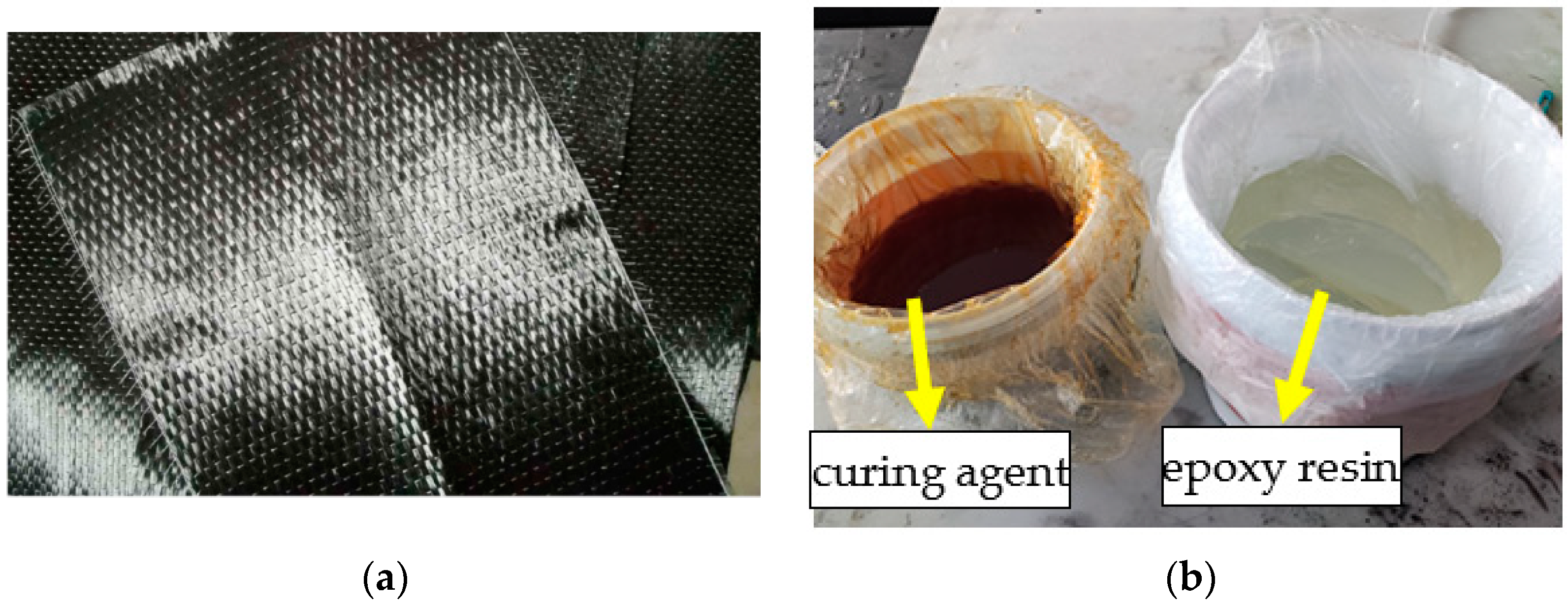
Figure 1.
Carbon fiber sheet and epoxy resin adhesive and: (a) carbon fiber sheet and (b) epoxy resin adhesive.
Figure 1.
Carbon fiber sheet and epoxy resin adhesive and: (a) carbon fiber sheet and (b) epoxy resin adhesive.
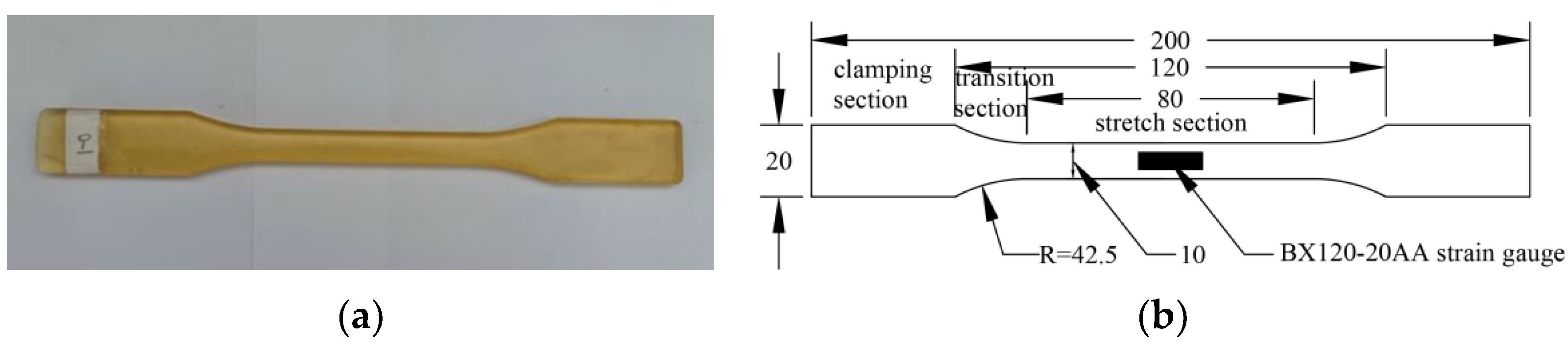
Figure 2.
Epoxy resin adhesive sheet: (a) sheet and (b) size and position of strain gauge.
Figure 2.
Epoxy resin adhesive sheet: (a) sheet and (b) size and position of strain gauge.
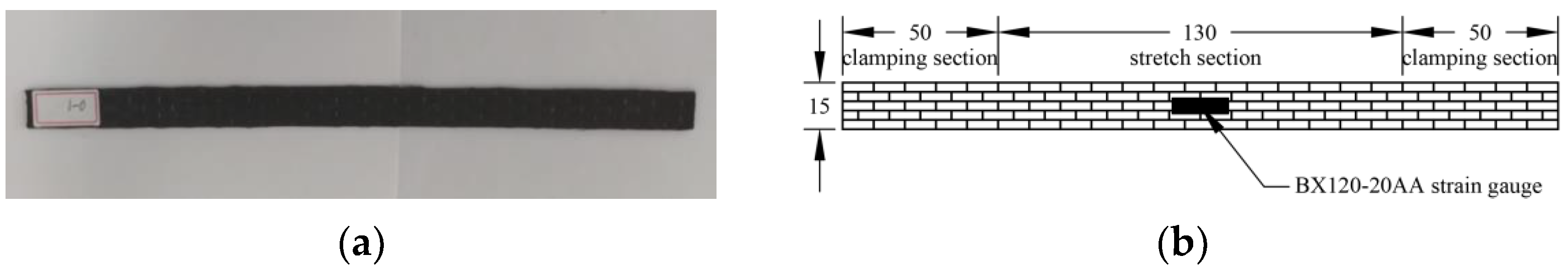
Figure 3.
CFRP sheet: (a) sheet and (b) size and position of strain gauge.
Figure 3.
CFRP sheet: (a) sheet and (b) size and position of strain gauge.
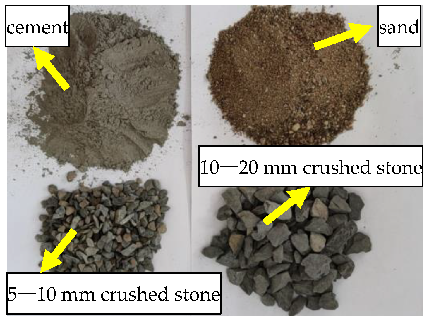
Figure 4.
Concrete composition materials.
Figure 4.
Concrete composition materials.
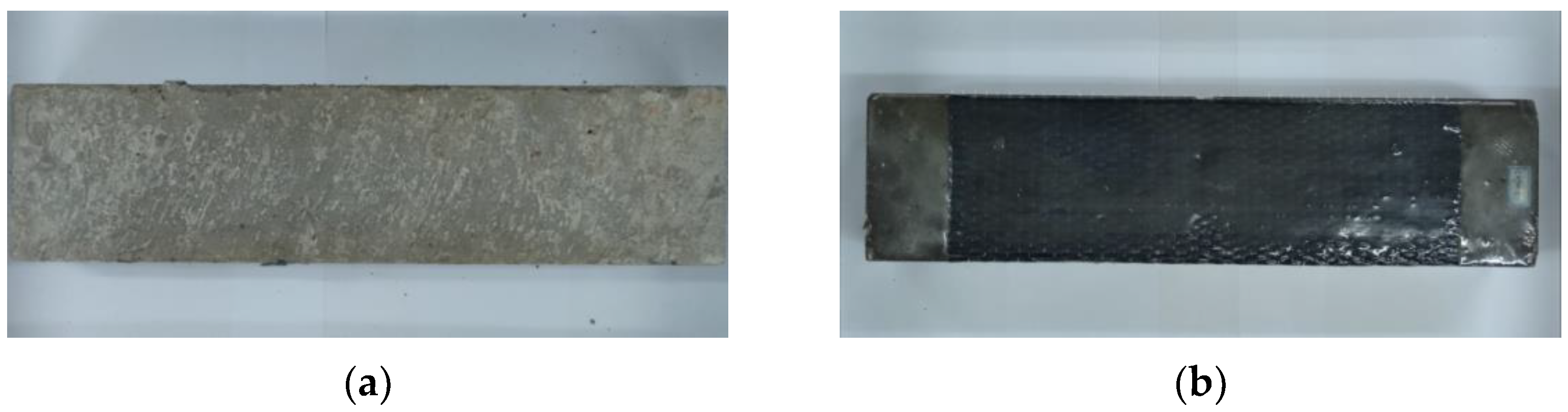
Figure 5.
Concrete flexural specimen: (a) unreinforced specimen and (b) reinforced specimen.
Figure 5.
Concrete flexural specimen: (a) unreinforced specimen and (b) reinforced specimen.
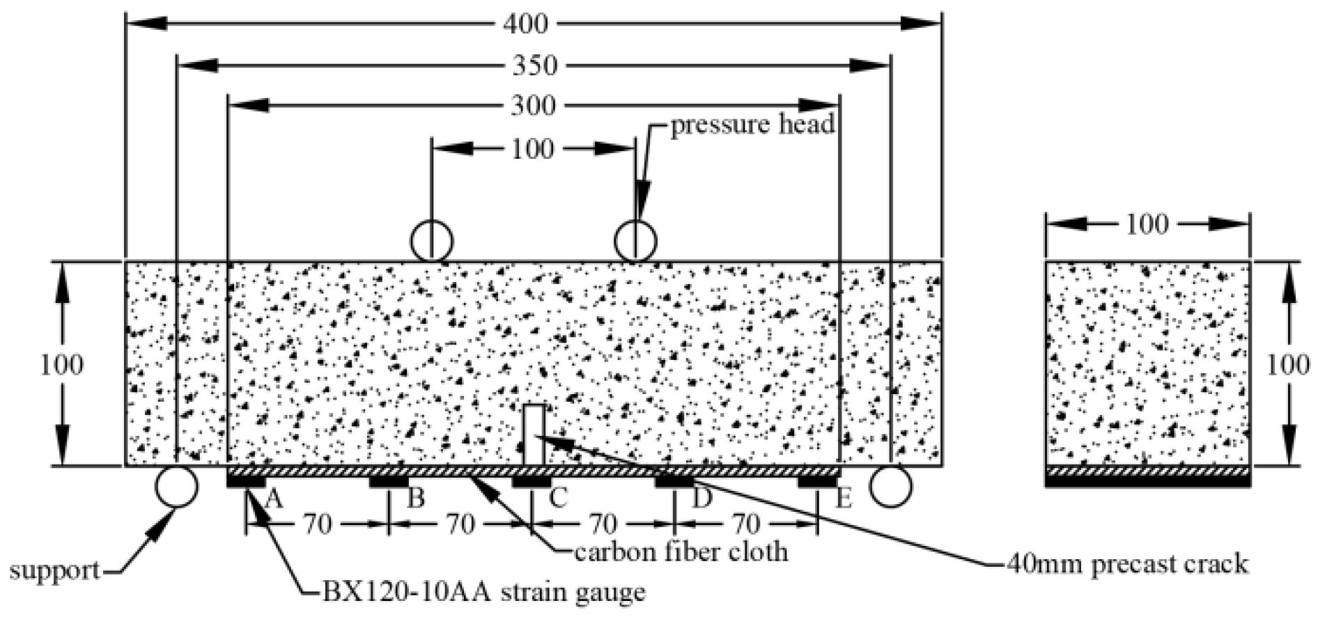
Figure 6.
Flexural testing set up.
Figure 6.
Flexural testing set up.
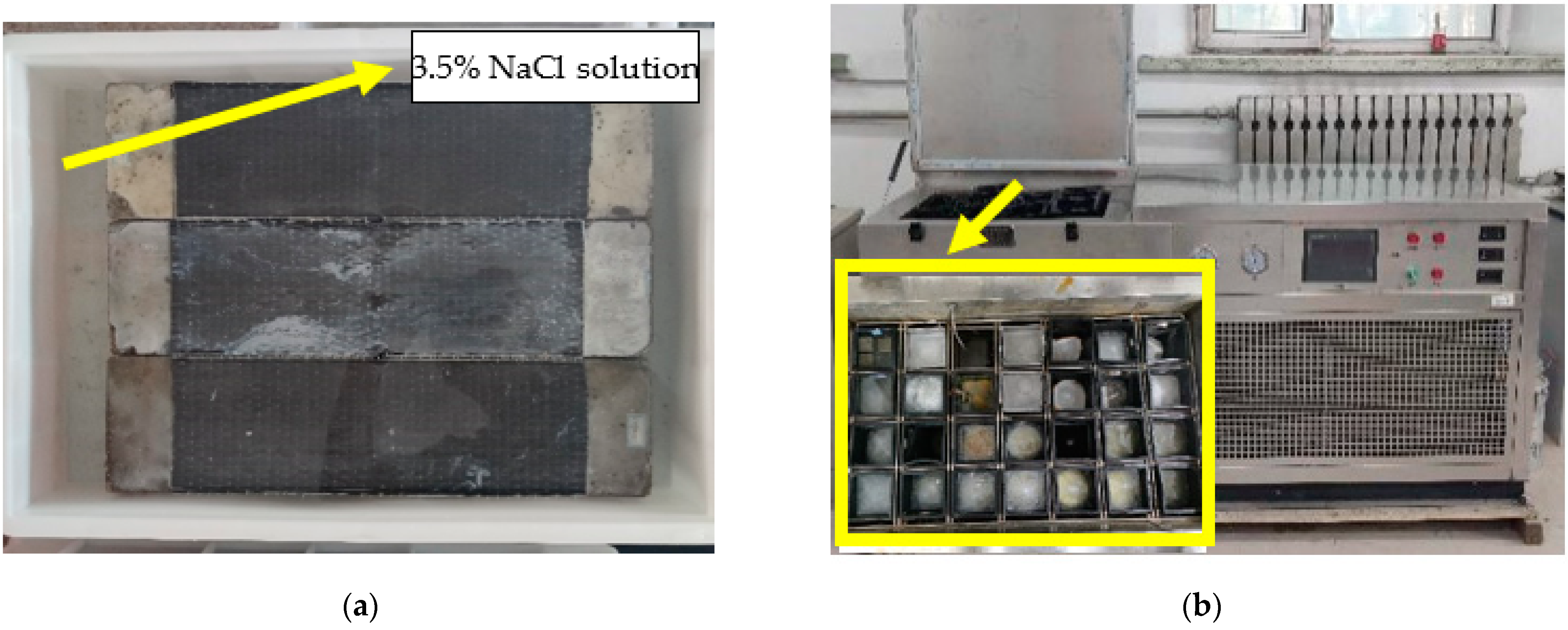
Figure 7.
Exposure environment: (a) chlorine salt immersion environment and (b) salt-freeze coupled environment.
Figure 7.
Exposure environment: (a) chlorine salt immersion environment and (b) salt-freeze coupled environment.
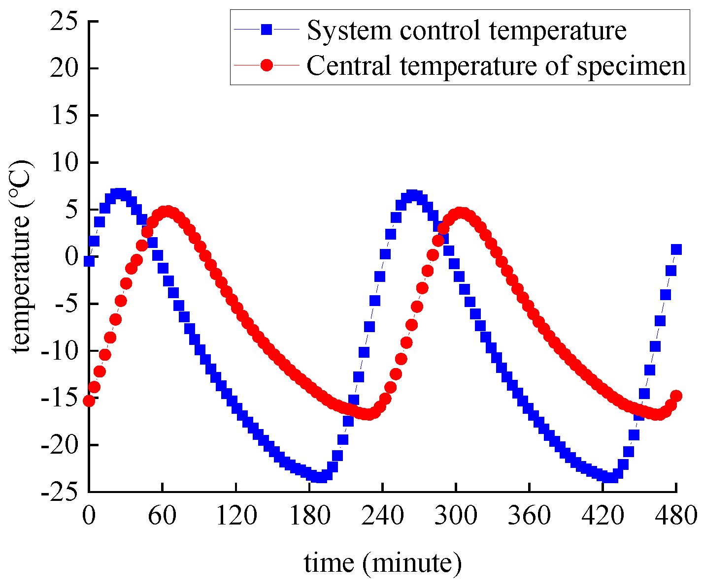
Figure 8.
Temperature curve.
Figure 8.
Temperature curve.
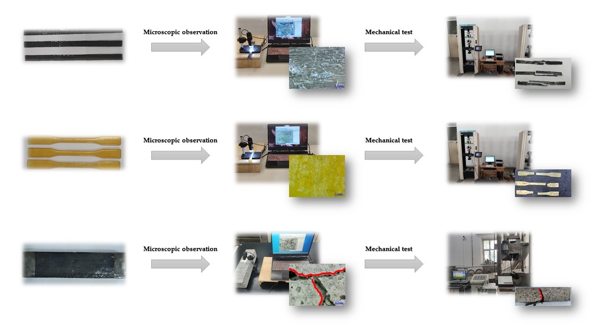
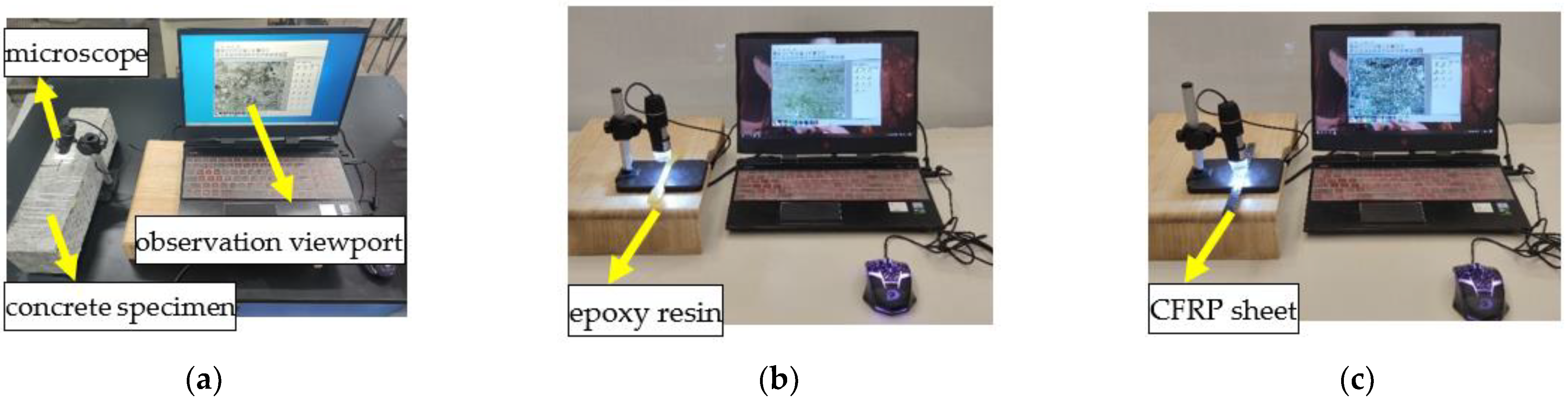
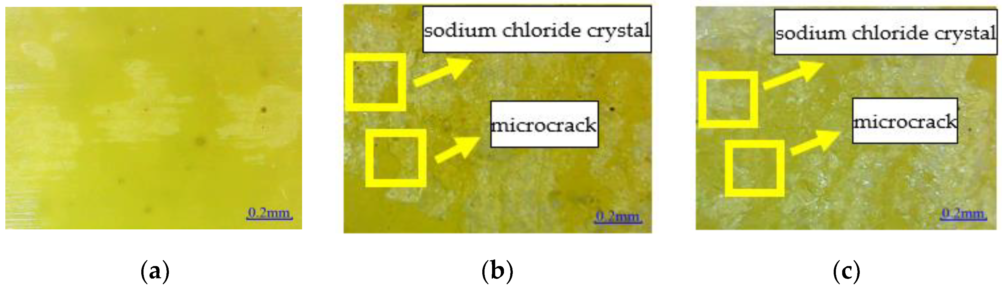
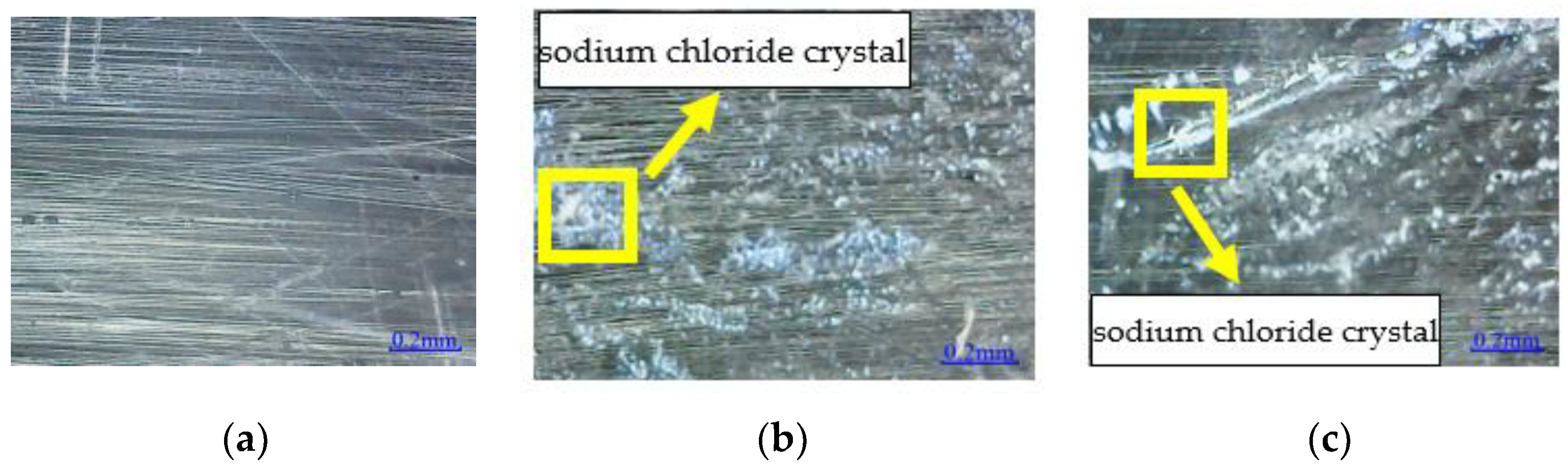
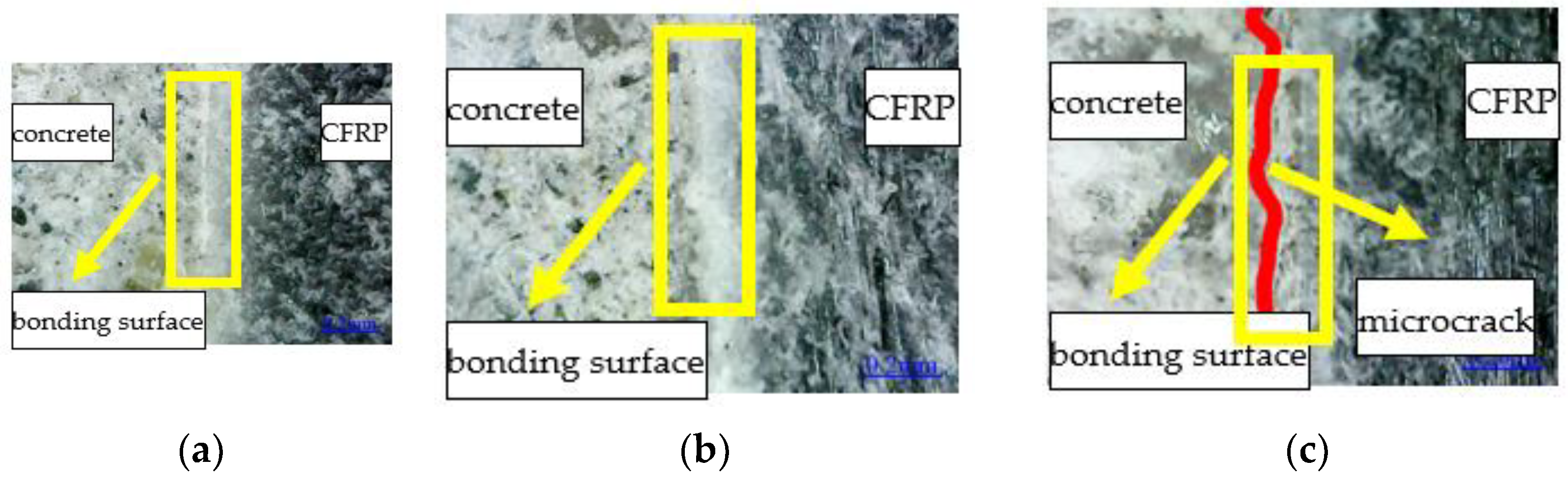
Figure 9.
Microscopic observation: (a) concrete flexural specimen; (b) epoxy resin sheet; and (c) CFRP sheet.
Figure 9.
Microscopic observation: (a) concrete flexural specimen; (b) epoxy resin sheet; and (c) CFRP sheet.
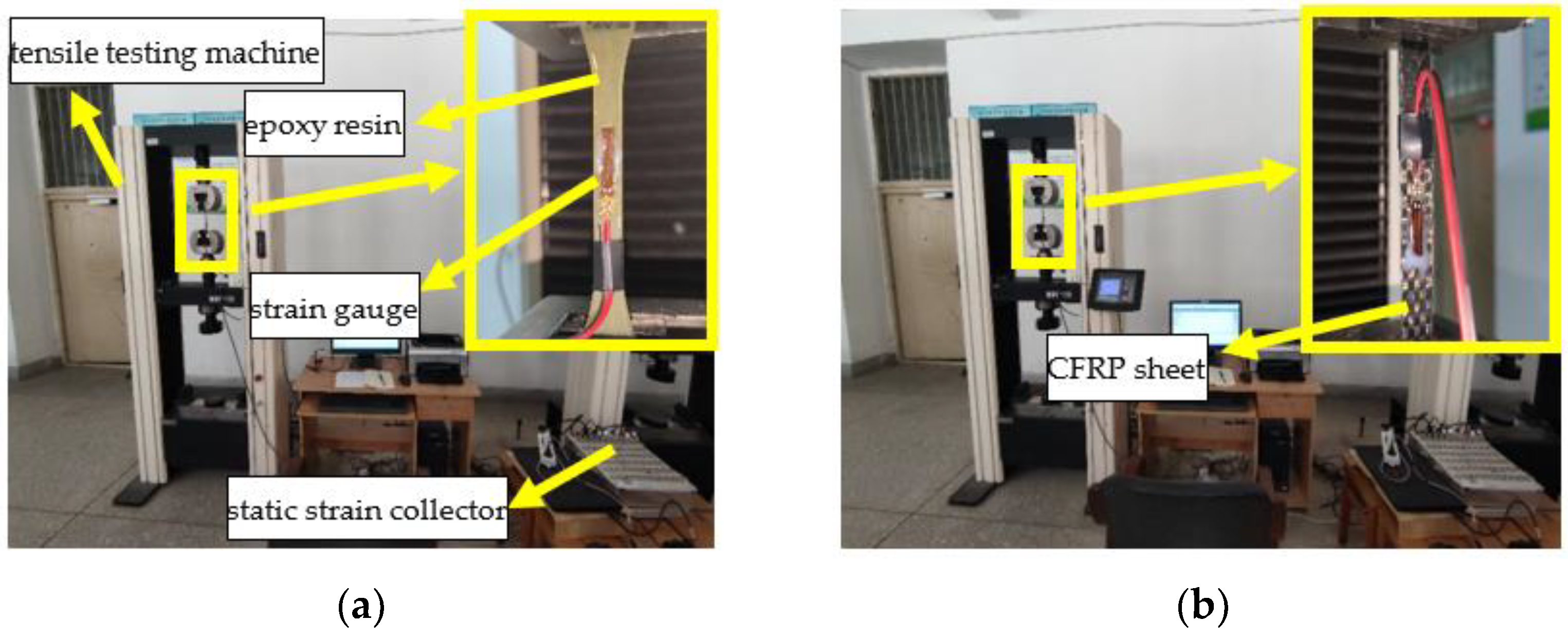
Figure 10.
Tensile mechanical test: (a) epoxy resin and (b) CFRP sheet.
Figure 10.
Tensile mechanical test: (a) epoxy resin and (b) CFRP sheet.
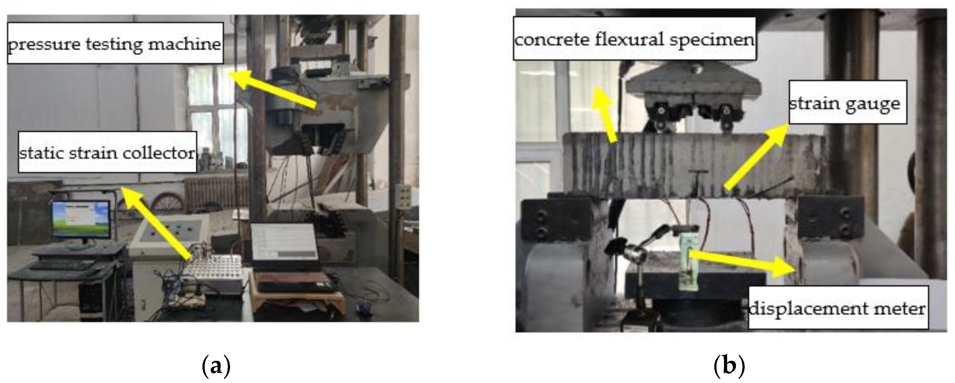
Figure 11.
Bending mechanical test: (a) load general setting and (b) detail data collection setting.
Figure 11.
Bending mechanical test: (a) load general setting and (b) detail data collection setting.
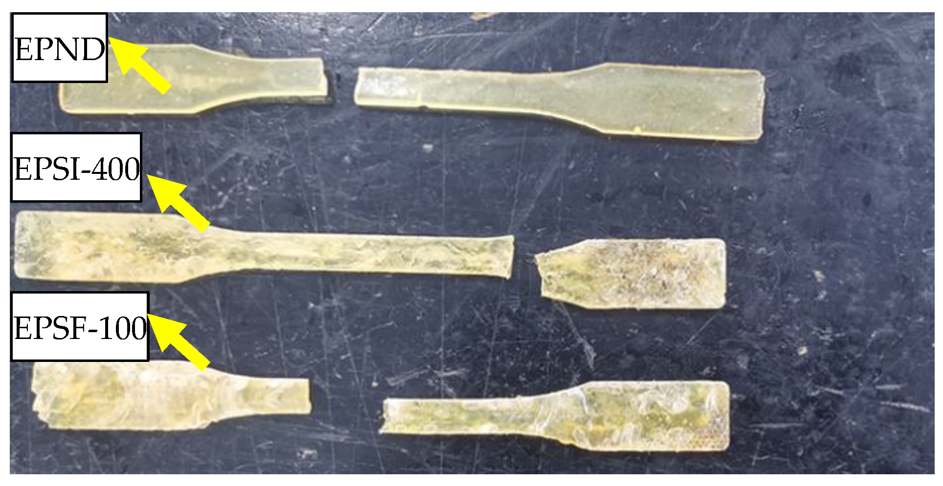
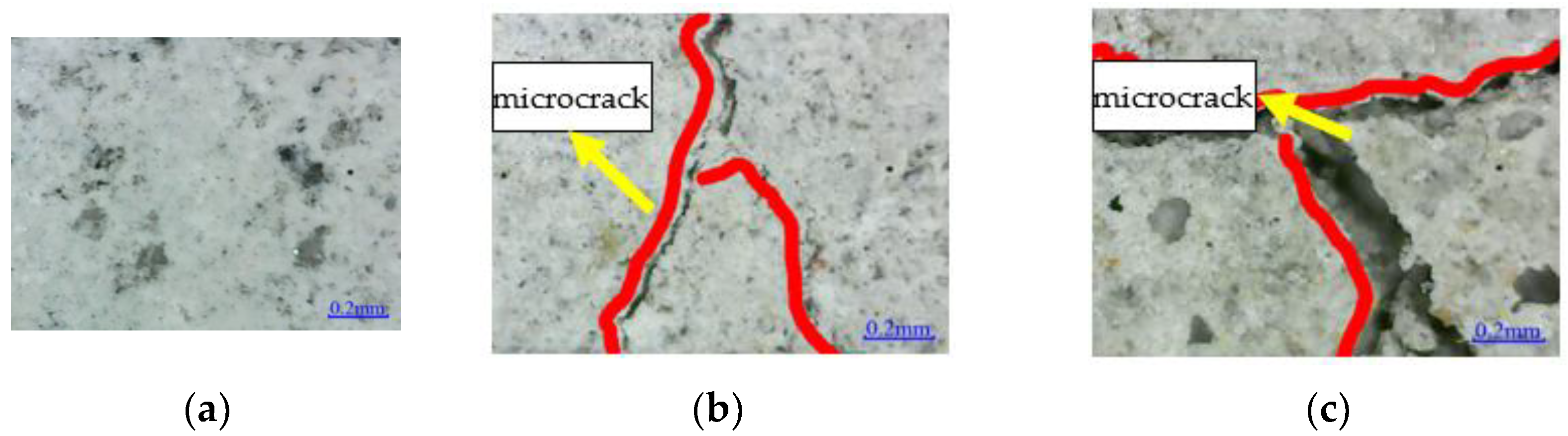
Figure 12.
Microstructure: (a) EPND; (b) EPSI-400; and (c) EPSF-100.
Figure 12.
Microstructure: (a) EPND; (b) EPSI-400; and (c) EPSF-100.
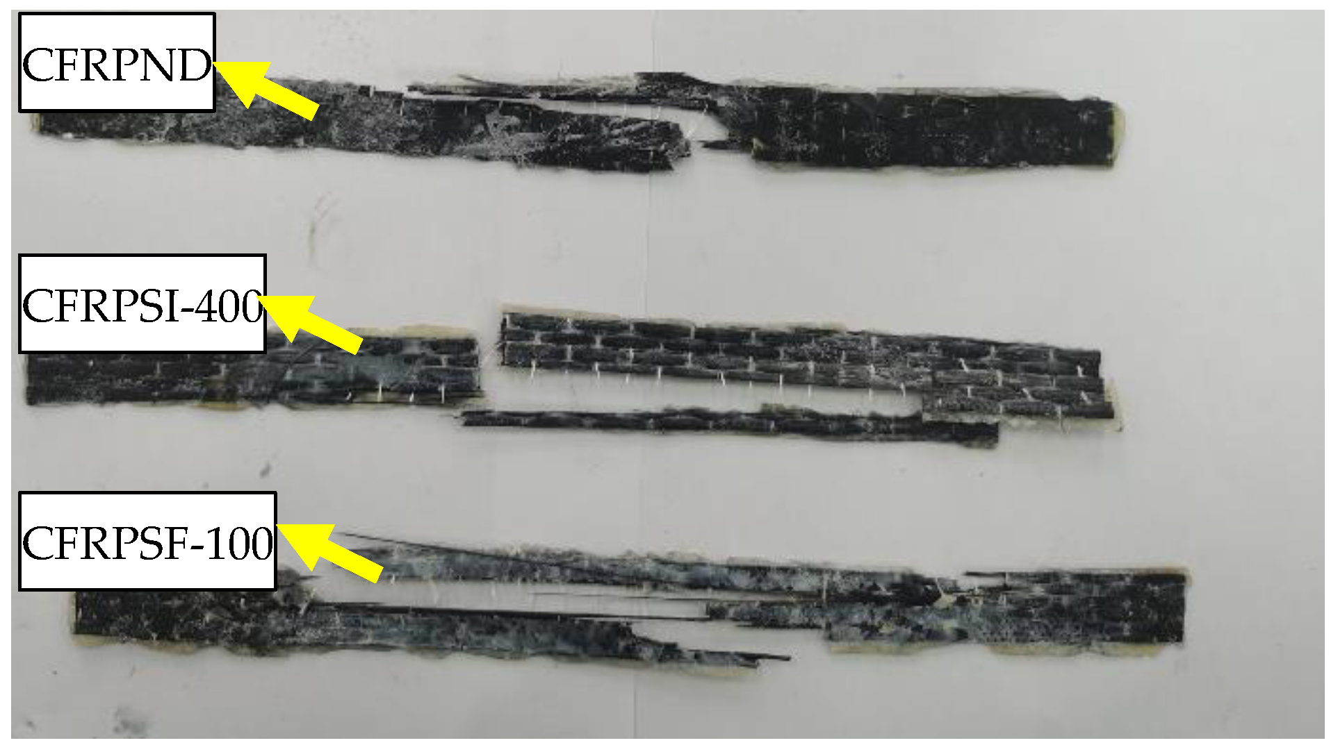
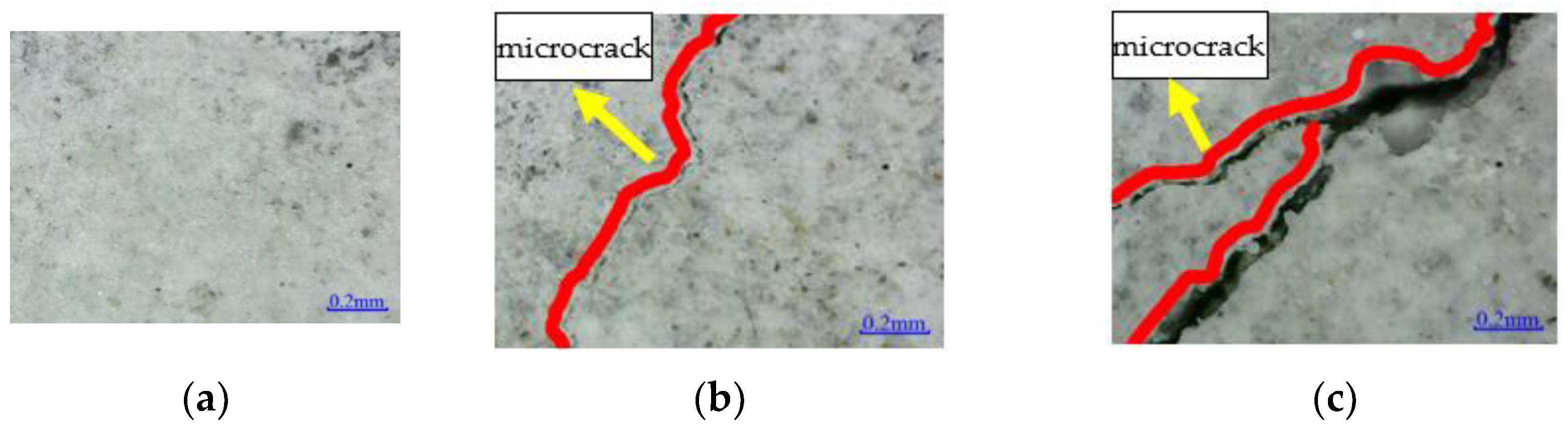
Figure 13.
Microstructure: (a) CFRPND; (b) CFRPSI-400; and (c) CFRPSF-100.
Figure 13.
Microstructure: (a) CFRPND; (b) CFRPSI-400; and (c) CFRPSF-100.
Figure 14.
Failure mode of epoxy resin.
Figure 14.
Failure mode of epoxy resin.
Figure 15.
Failure mode of CFRP sheet.
Figure 15.
Failure mode of CFRP sheet.
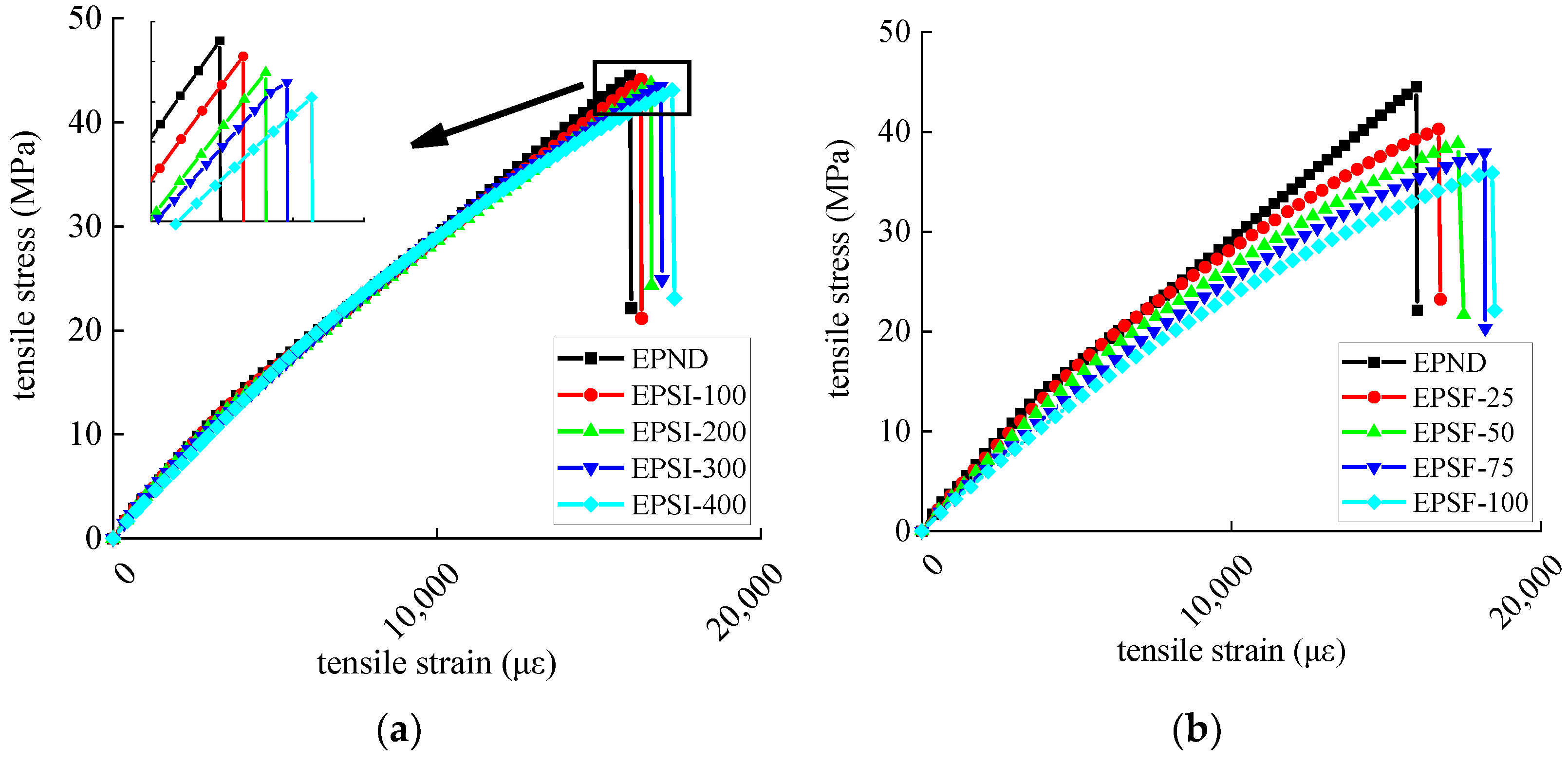
Figure 16.
Stress–strain curve of epoxy resin: (a) chlorine salt immersion environment and (b) salt-freeze coupled environment.
Figure 16.
Stress–strain curve of epoxy resin: (a) chlorine salt immersion environment and (b) salt-freeze coupled environment.
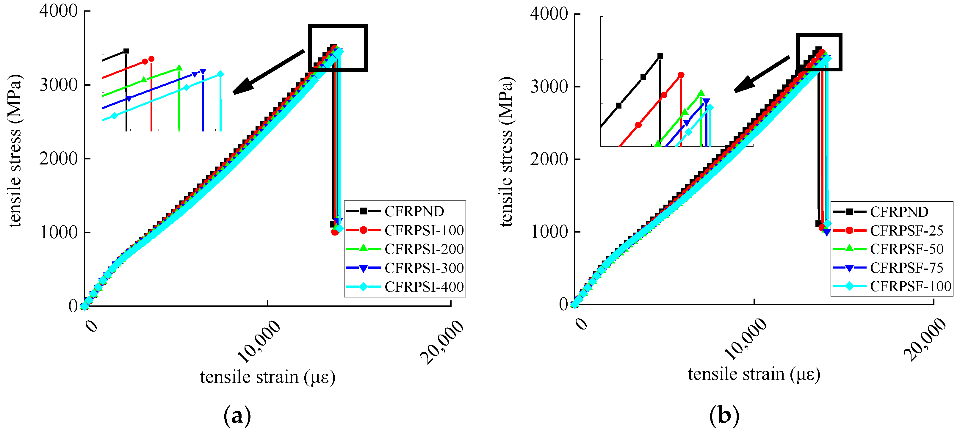
Figure 17.
Stress–strain curve of CFRP sheet: (a) chlorine salt immersion environment and (b) salt-freeze coupled environment.
Figure 17.
Stress–strain curve of CFRP sheet: (a) chlorine salt immersion environment and (b) salt-freeze coupled environment.
Figure 18.
Microstructure of concrete surface: (a) URFND; (b) URFSI-400; and (c) URFSF-100.
Figure 18.
Microstructure of concrete surface: (a) URFND; (b) URFSI-400; and (c) URFSF-100.
Figure 19.
Microstructure of concrete surface: (a) RFND; (b) RFSI-400; and (c) RFSF-100.
Figure 19.
Microstructure of concrete surface: (a) RFND; (b) RFSI-400; and (c) RFSF-100.
Figure 20.
Microstructure of bonding surface between CFRP and concrete: (a) RFND; (b) RFSI-400; and (c) RFSF-100.
Figure 20.
Microstructure of bonding surface between CFRP and concrete: (a) RFND; (b) RFSI-400; and (c) RFSF-100.
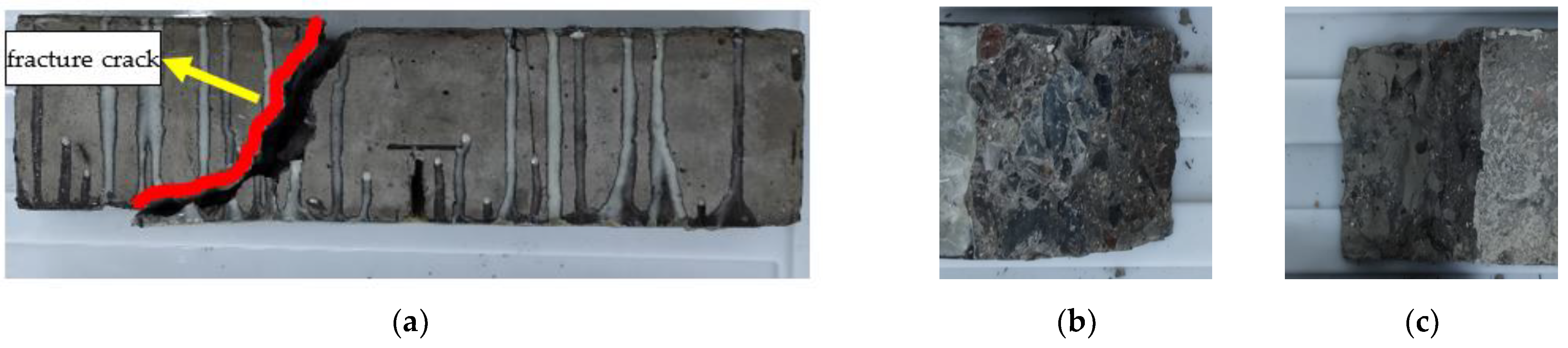
Figure 21.
Failure mode of URFND: (a) side surface; (b) fracture surface 1; and (c) fracture surface 2.
Figure 21.
Failure mode of URFND: (a) side surface; (b) fracture surface 1; and (c) fracture surface 2.
Figure 22.
Failure mode of URFSI-400: (a) side surface; (b) fracture surface 1; and (c) fracture surface 2.
Figure 22.
Failure mode of URFSI-400: (a) side surface; (b) fracture surface 1; and (c) fracture surface 2.
Figure 23.
Failure mode of URFSF-100: (a) side surface; (b) fracture surface 1; and (c) fracture surface 2.
Figure 23.
Failure mode of URFSF-100: (a) side surface; (b) fracture surface 1; and (c) fracture surface 2.
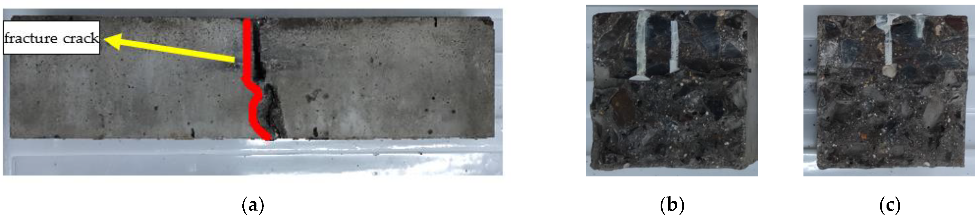
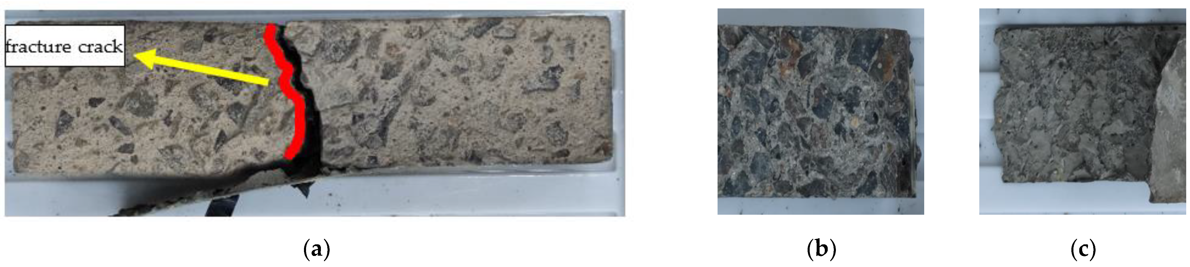
Figure 24.
Failure mode of RFND: (a) side surface; (b) fracture surface 1; and (c) fracture surface 2.
Figure 24.
Failure mode of RFND: (a) side surface; (b) fracture surface 1; and (c) fracture surface 2.
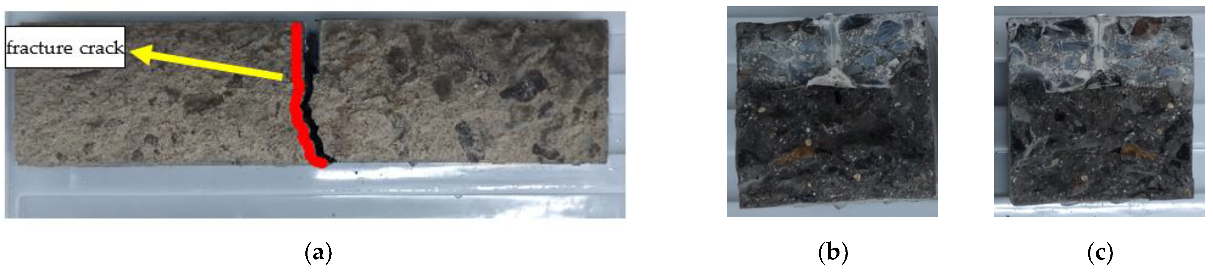
Figure 25.
Failure mode of RFSI-400: (a) side surface; (b) fracture surface 1; and (c) fracture surface 2.
Figure 25.
Failure mode of RFSI-400: (a) side surface; (b) fracture surface 1; and (c) fracture surface 2.
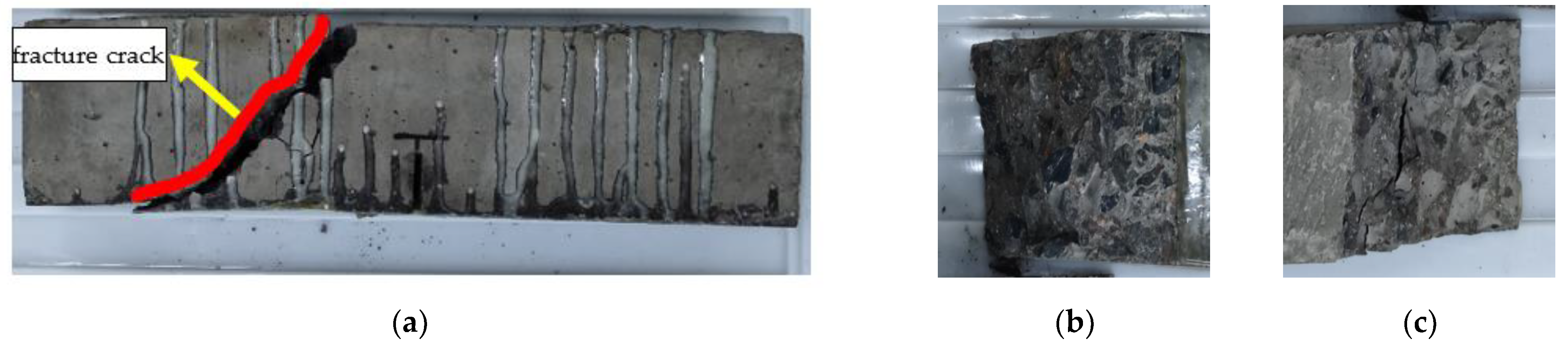
Figure 26.
Failure mode of RFSF-100: (a) side surface; (b) concrete bonding surface; and (c) CFRP bonding surface.
Figure 26.
Failure mode of RFSF-100: (a) side surface; (b) concrete bonding surface; and (c) CFRP bonding surface.
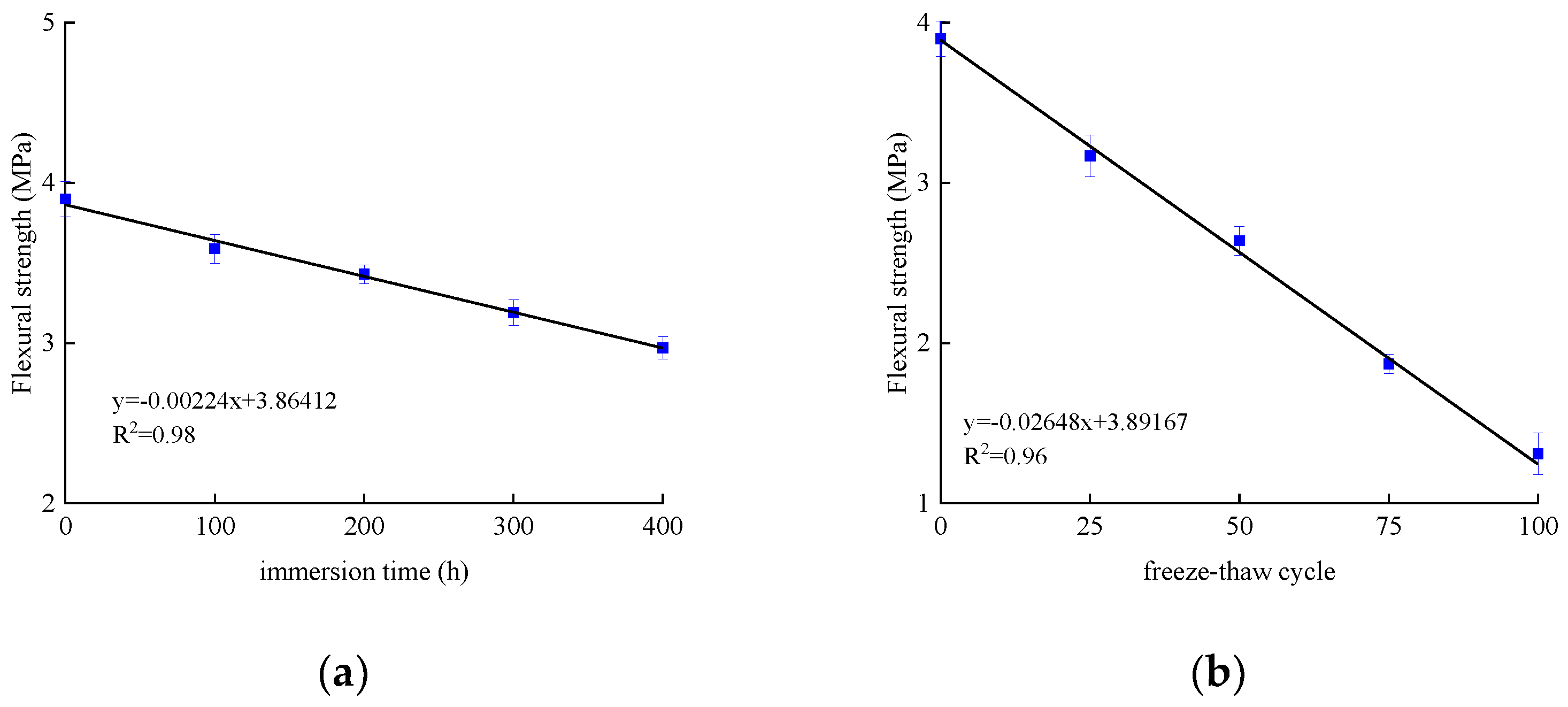
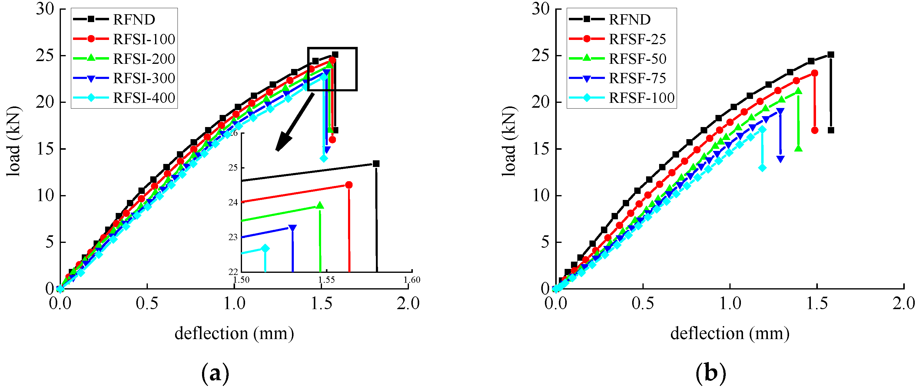
Figure 27.
Flexural strength of unreinforced concrete specimen: (a) chlorine salt immersion environment and (b) salt-freeze coupled environment.
Figure 27.
Flexural strength of unreinforced concrete specimen: (a) chlorine salt immersion environment and (b) salt-freeze coupled environment.
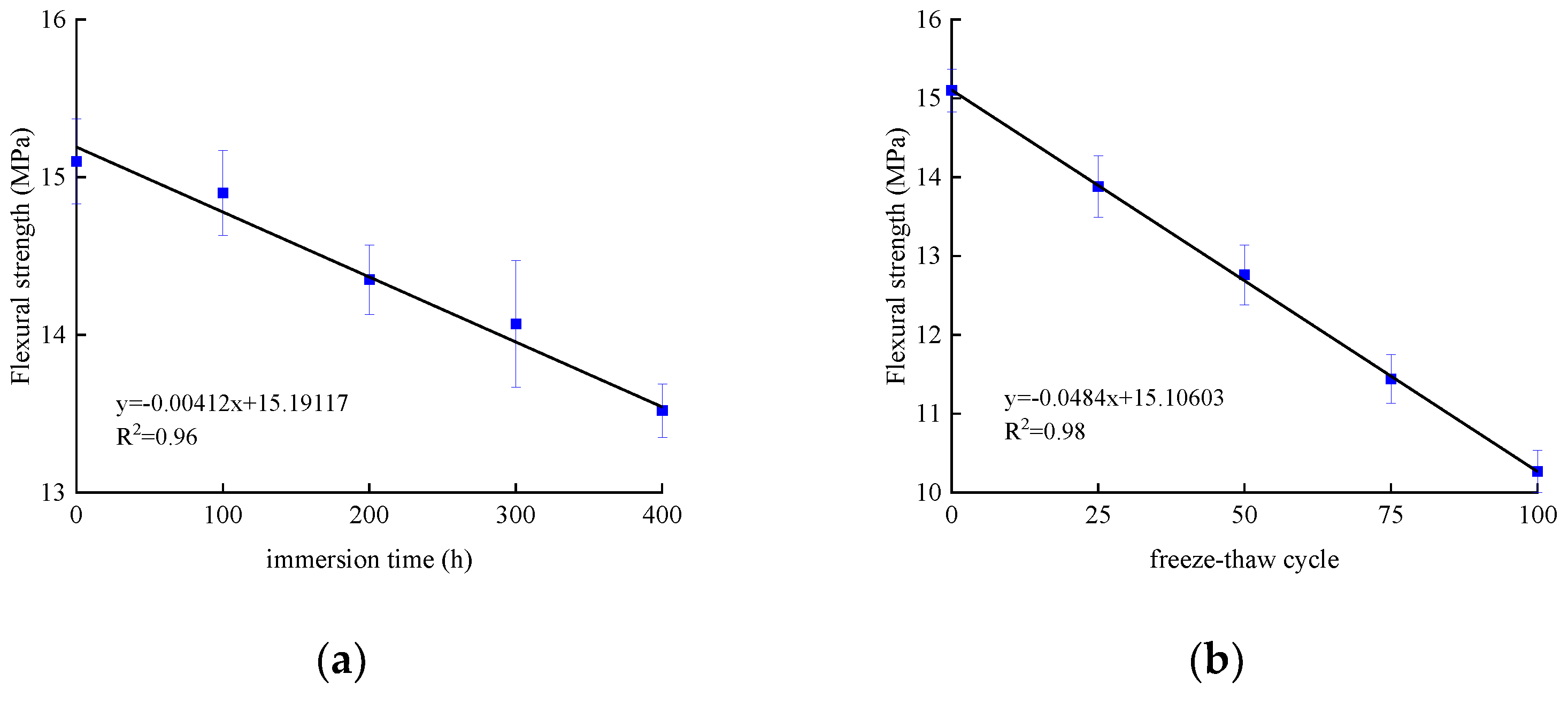
Figure 28.
Flexural strength of reinforced concrete specimen: (a) chlorine salt immersion environment; and (b) salt-freeze coupled environment.
Figure 28.
Flexural strength of reinforced concrete specimen: (a) chlorine salt immersion environment; and (b) salt-freeze coupled environment.
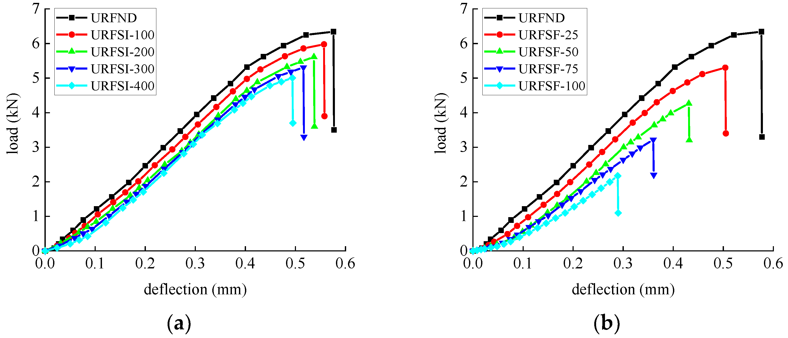
Figure 29.
Load-deflection curve of unreinforced concrete flexural specimen: (a) chlorine salt immersion environment and (b) salt-freeze coupled environment.
Figure 29.
Load-deflection curve of unreinforced concrete flexural specimen: (a) chlorine salt immersion environment and (b) salt-freeze coupled environment.
Figure 30.
Load-deflection curve of reinforced concrete flexural specimen: (a) chlorine salt immersion environment and (b) salt-freeze coupled environment.
Figure 30.
Load-deflection curve of reinforced concrete flexural specimen: (a) chlorine salt immersion environment and (b) salt-freeze coupled environment.
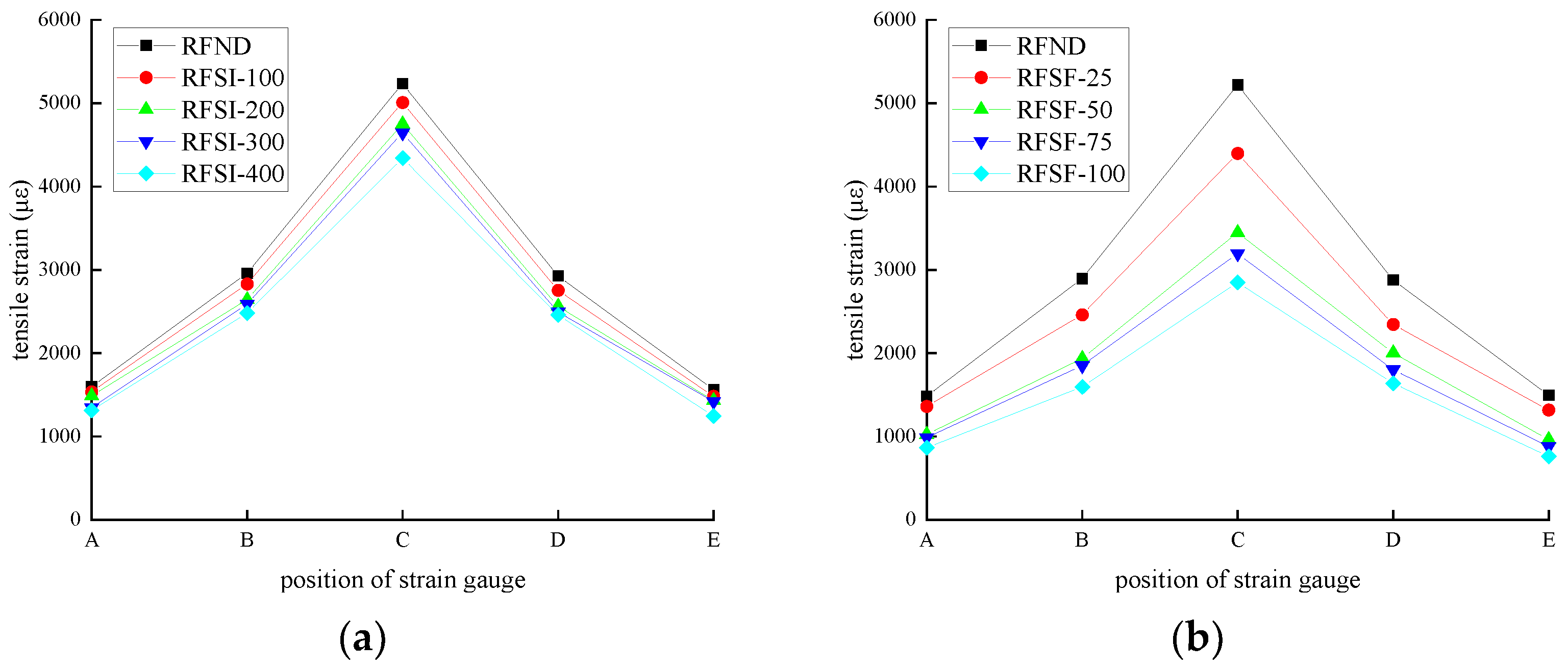
Figure 31.
Strain of CFRP strip: (a) chlorine salt immersion environment and (b) salt-freeze coupled environment.
Figure 31.
Strain of CFRP strip: (a) chlorine salt immersion environment and (b) salt-freeze coupled environment.
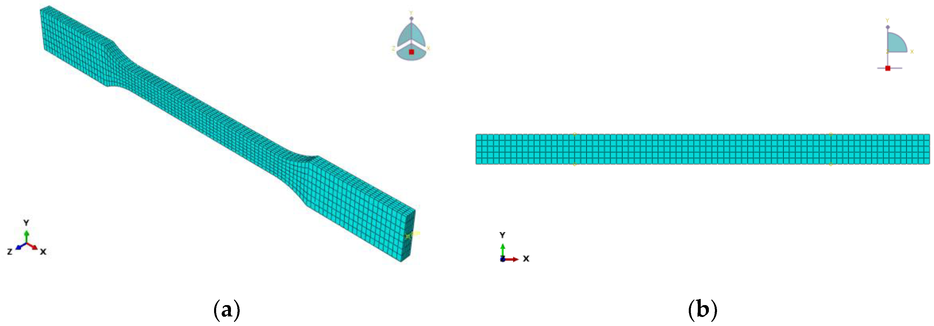
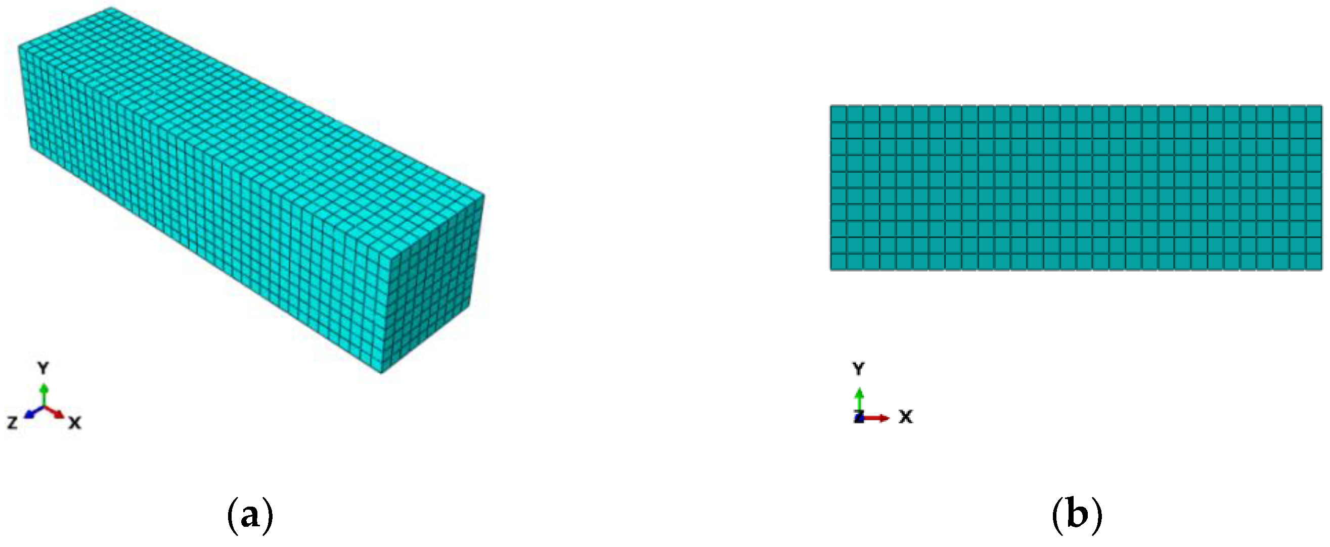
Figure 32.
Mesh Dividing: (a) epoxy resin adhesive sheet and (b) CFRP sheet.
Figure 32.
Mesh Dividing: (a) epoxy resin adhesive sheet and (b) CFRP sheet.
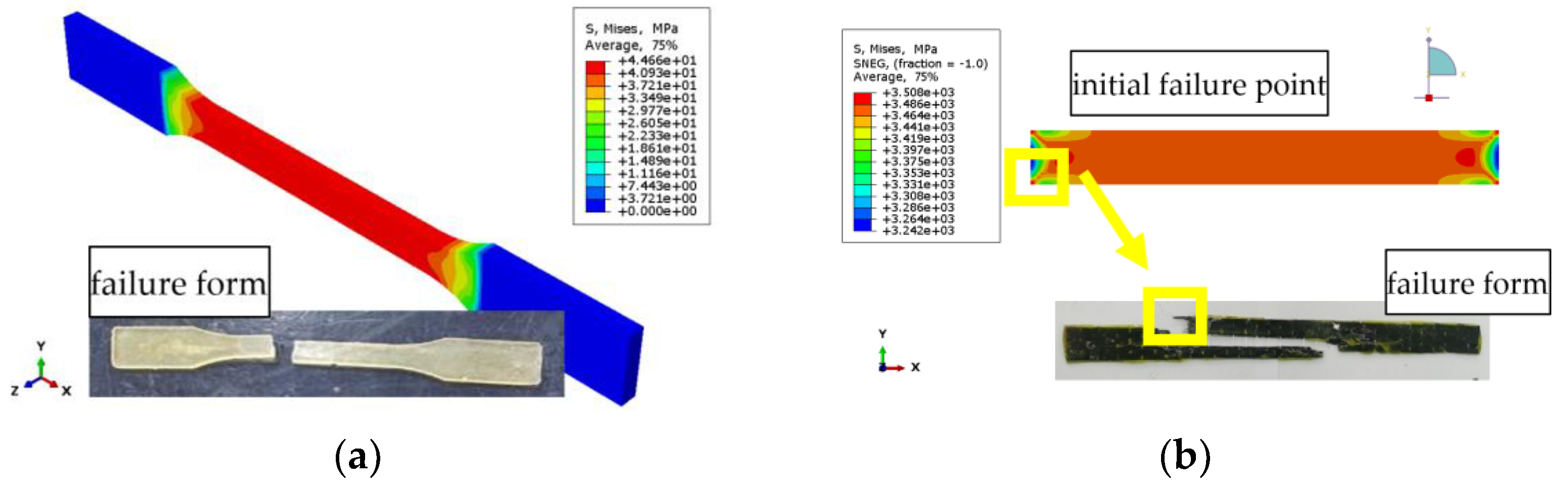
Figure 33.
Stress nephogram: (a) Epoxy resin; (b) CFRP sheet.
Figure 33.
Stress nephogram: (a) Epoxy resin; (b) CFRP sheet.
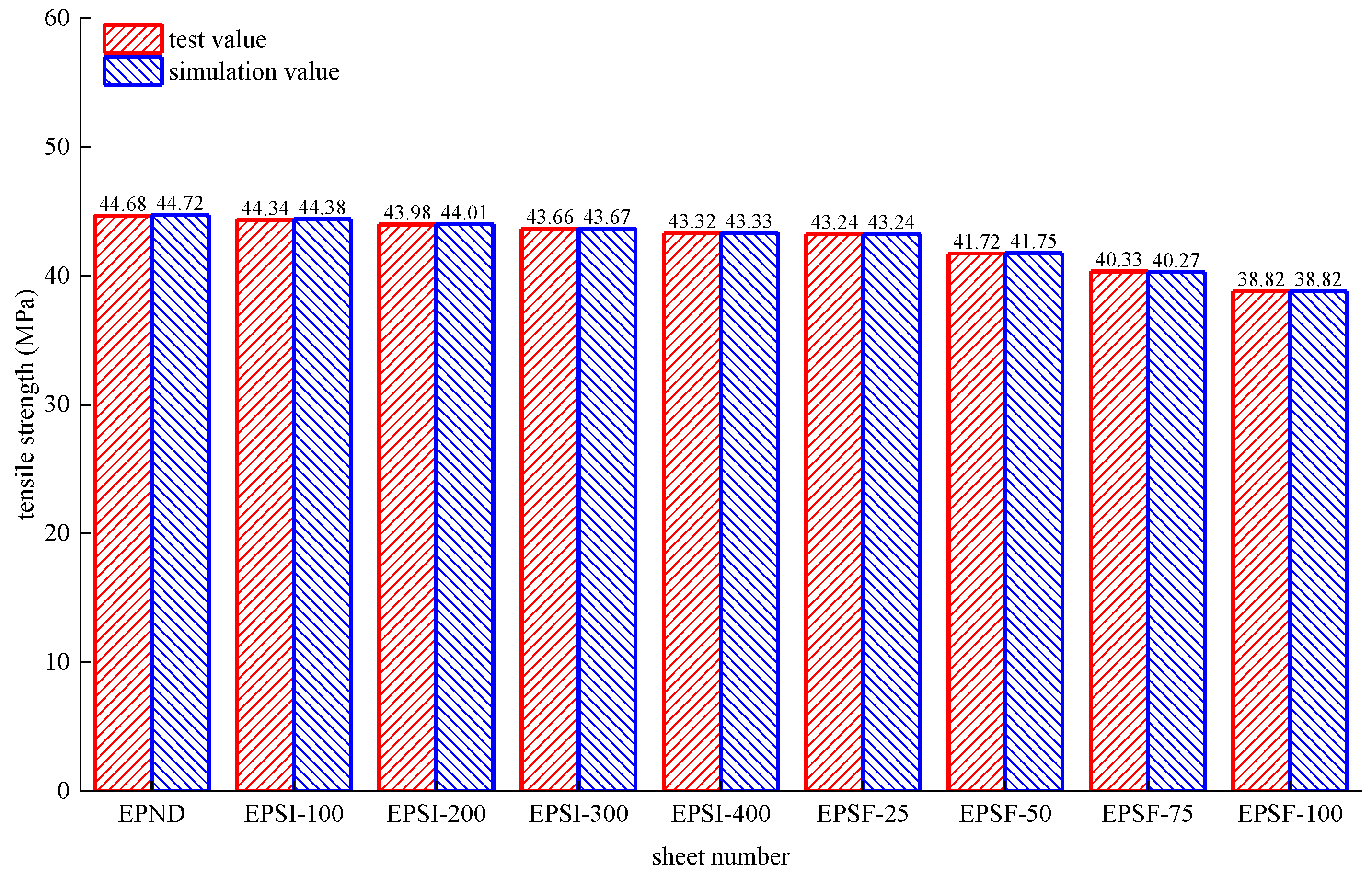
Figure 34.
Test values and simulated values of tensile strength of epoxy resin.
Figure 34.
Test values and simulated values of tensile strength of epoxy resin.
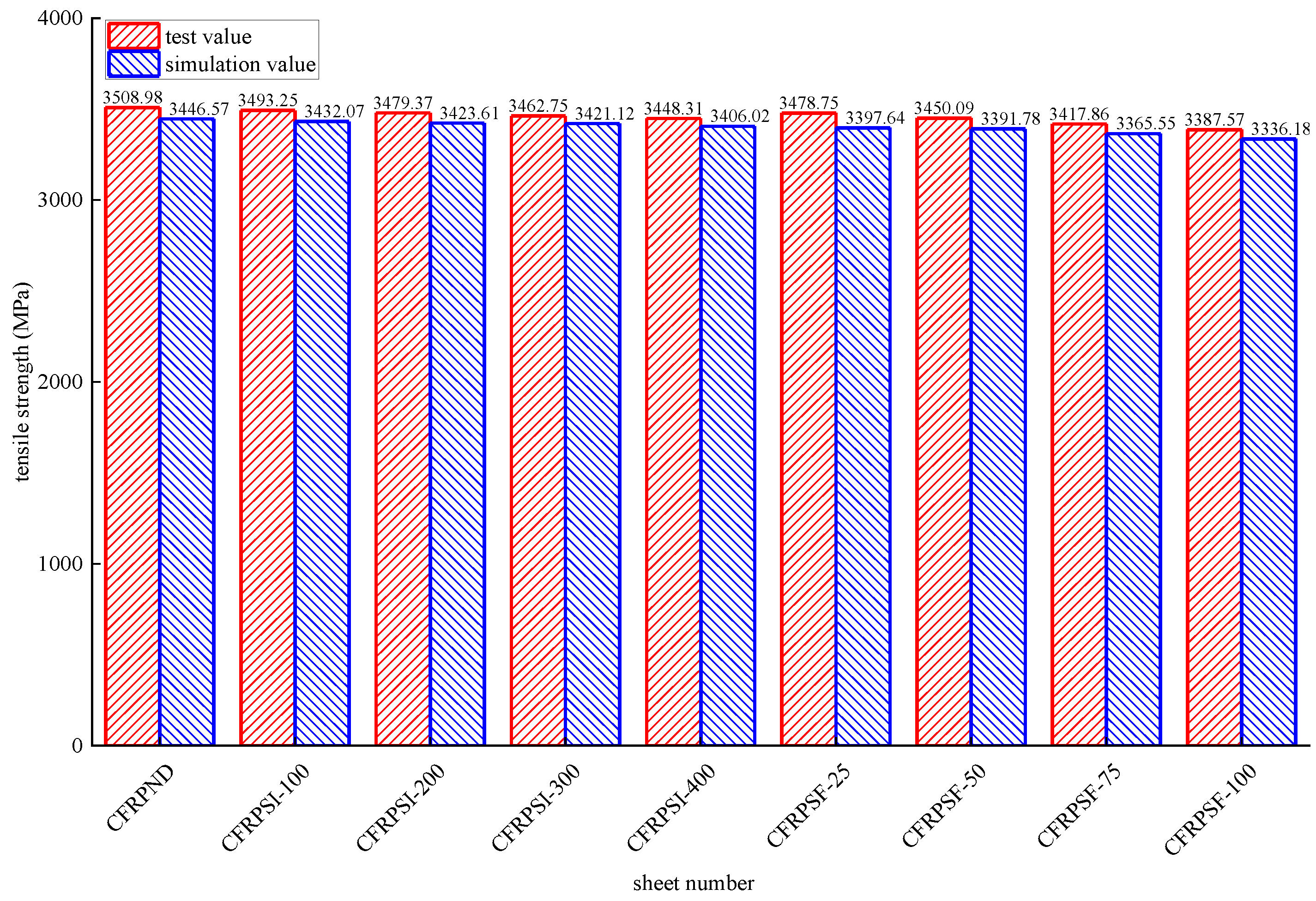
Figure 35.
Test values and simulated values of tensile strength of CFRP sheet.
Figure 35.
Test values and simulated values of tensile strength of CFRP sheet.
Figure 36.
Mesh Dividing: (a) Concrete; (b) CFRP.
Figure 36.
Mesh Dividing: (a) Concrete; (b) CFRP.
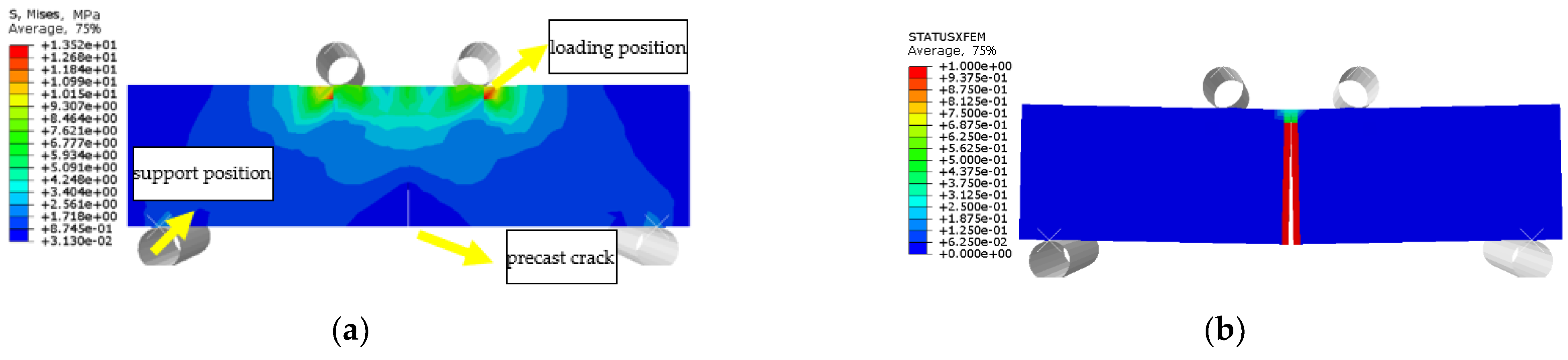
Figure 37.
URFND: (a) stress nephogram and (b) damage nephogram of prefabricated crack.
Figure 37.
URFND: (a) stress nephogram and (b) damage nephogram of prefabricated crack.
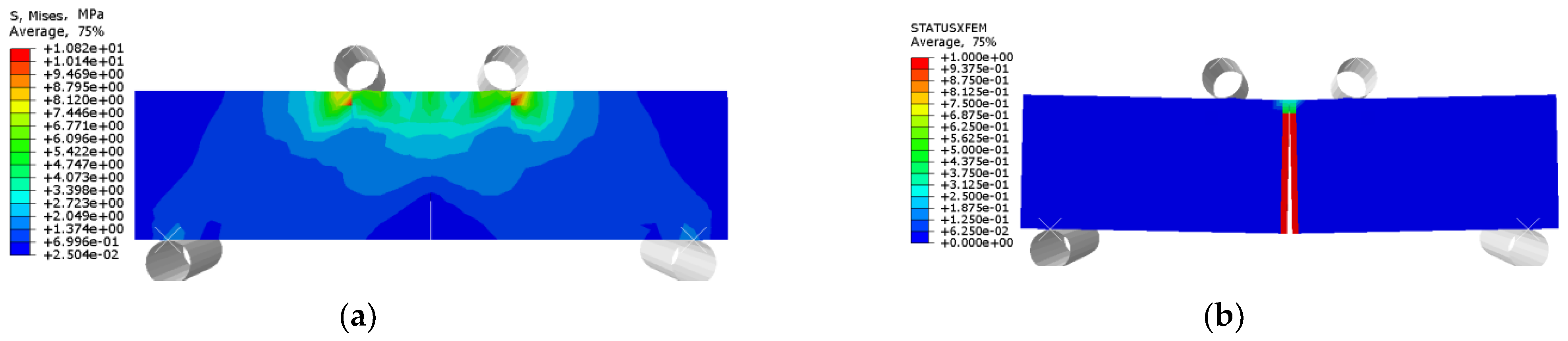
Figure 38.
URFSI-400: (a) stress nephogram and (b) damage nephogram of prefabricated crack.
Figure 38.
URFSI-400: (a) stress nephogram and (b) damage nephogram of prefabricated crack.
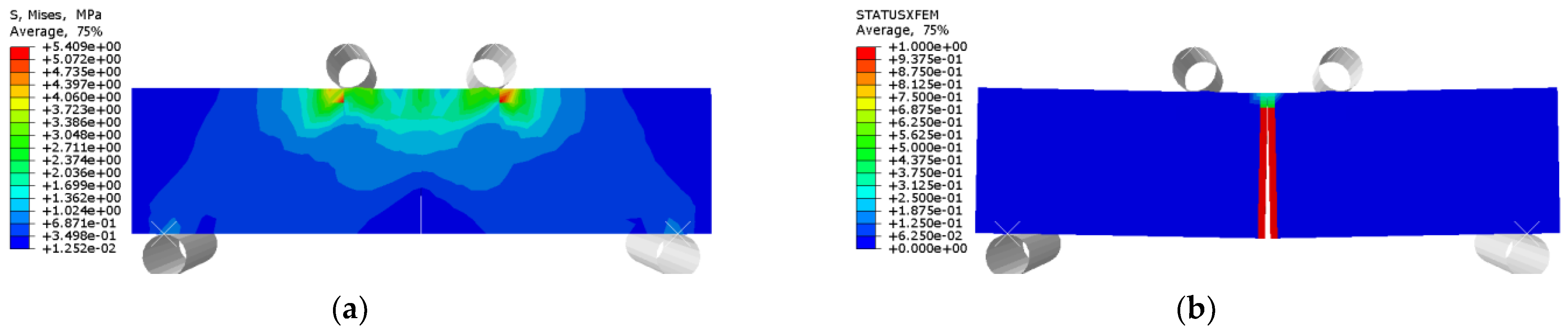
Figure 39.
URFSF-100: (a) stress nephogram and (b) damage nephogram of prefabricated crack.
Figure 39.
URFSF-100: (a) stress nephogram and (b) damage nephogram of prefabricated crack.
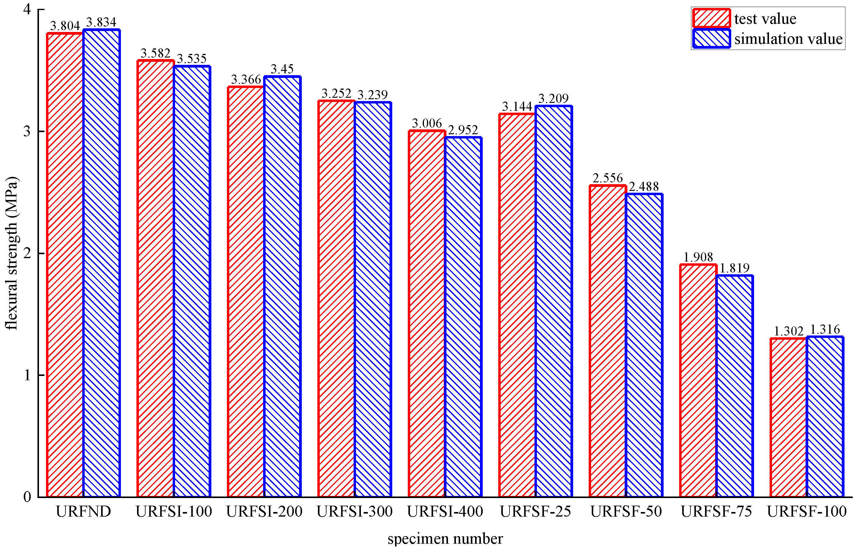
Figure 40.
Test values and simulated values of flexural strength of unreinforced concrete flexural specimen.
Figure 40.
Test values and simulated values of flexural strength of unreinforced concrete flexural specimen.
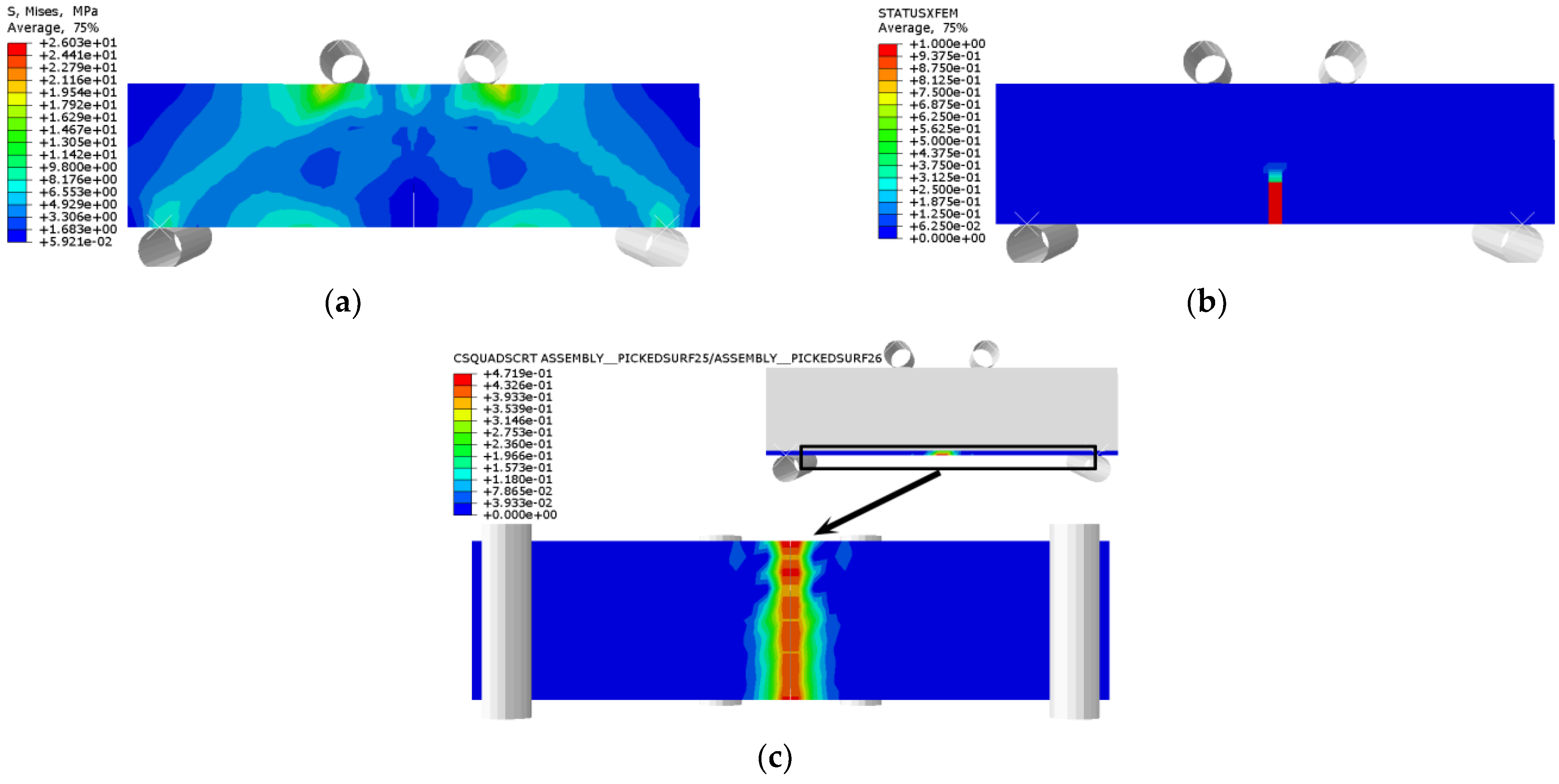
Figure 41.
RFND: (a) stress nephogram; (b) damage nephogram of prefabricated crack; and (c) damage nephogram of bonding surface.
Figure 41.
RFND: (a) stress nephogram; (b) damage nephogram of prefabricated crack; and (c) damage nephogram of bonding surface.
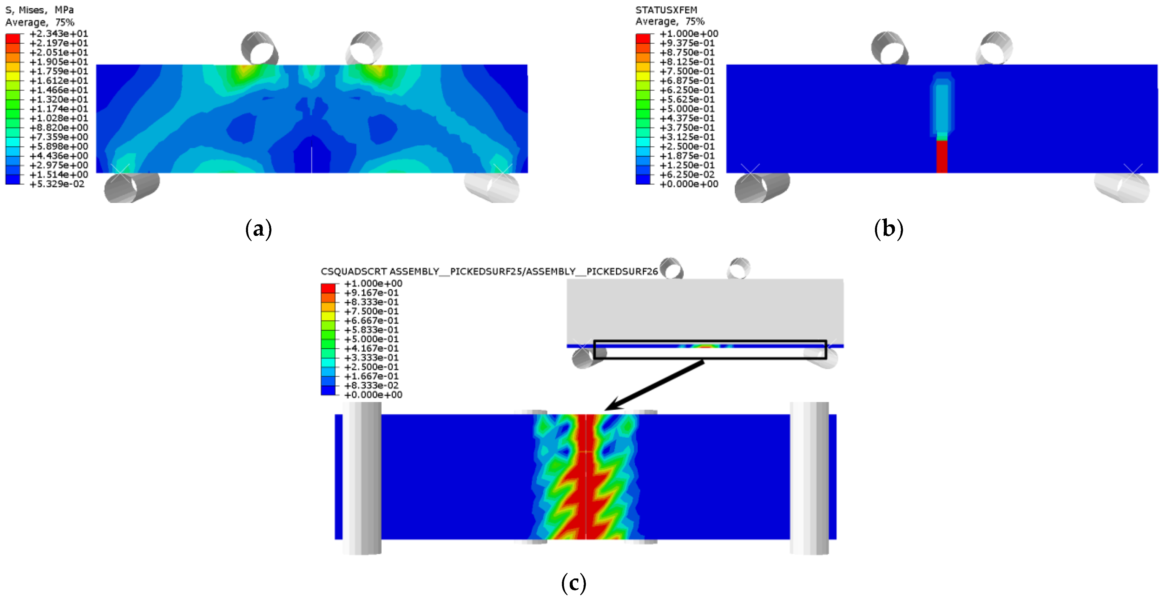
Figure 42.
RFSI-400: (a) stress nephogram; (b) damage nephogram of prefabricated crack; and (c) damage nephogram of bonding surface.
Figure 42.
RFSI-400: (a) stress nephogram; (b) damage nephogram of prefabricated crack; and (c) damage nephogram of bonding surface.
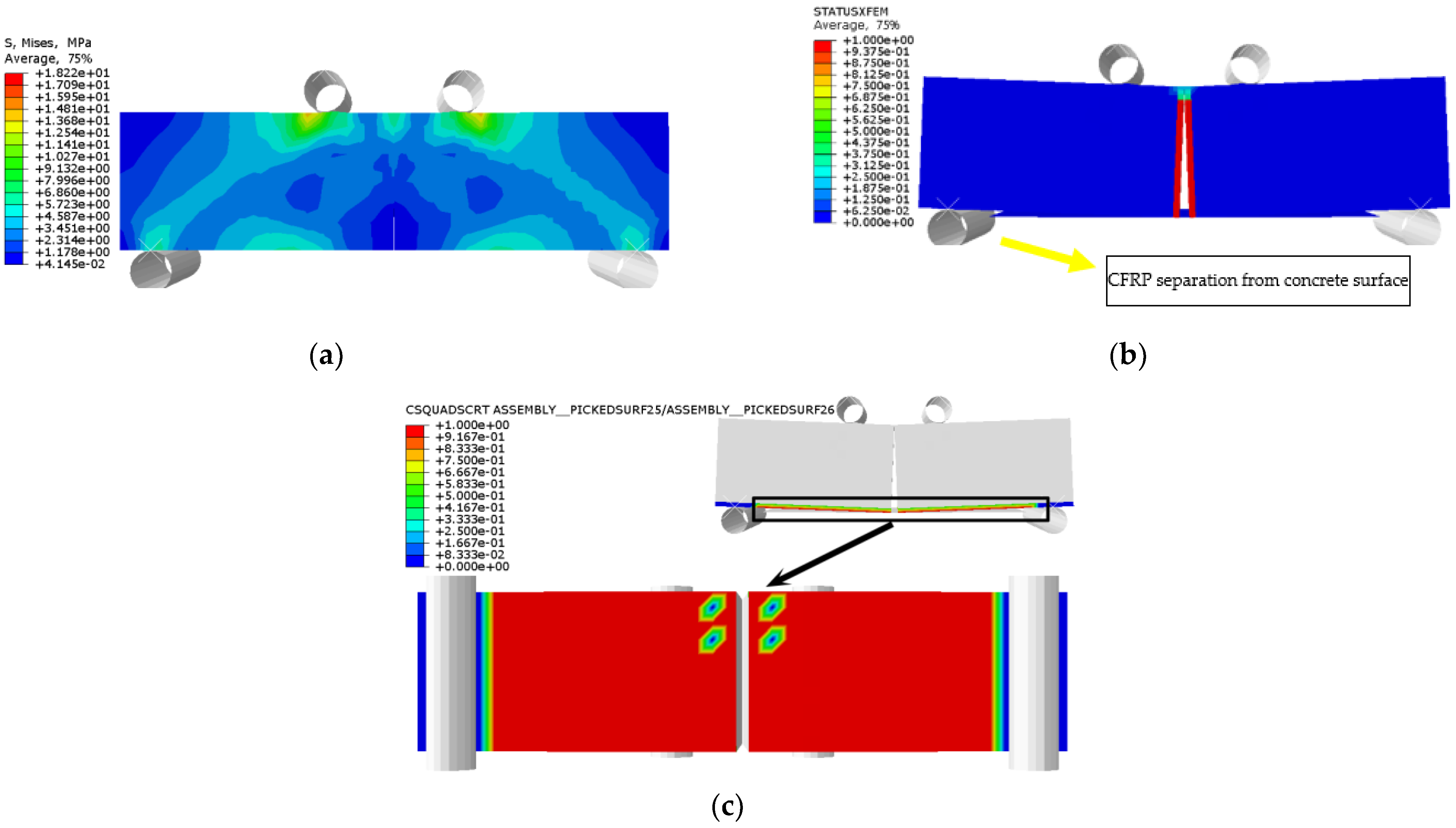
Figure 43.
RFSF-100: (a) stress nephogram; (b) damage nephogram of prefabricated crack; and (c) damage nephogram of bonding surface.
Figure 43.
RFSF-100: (a) stress nephogram; (b) damage nephogram of prefabricated crack; and (c) damage nephogram of bonding surface.
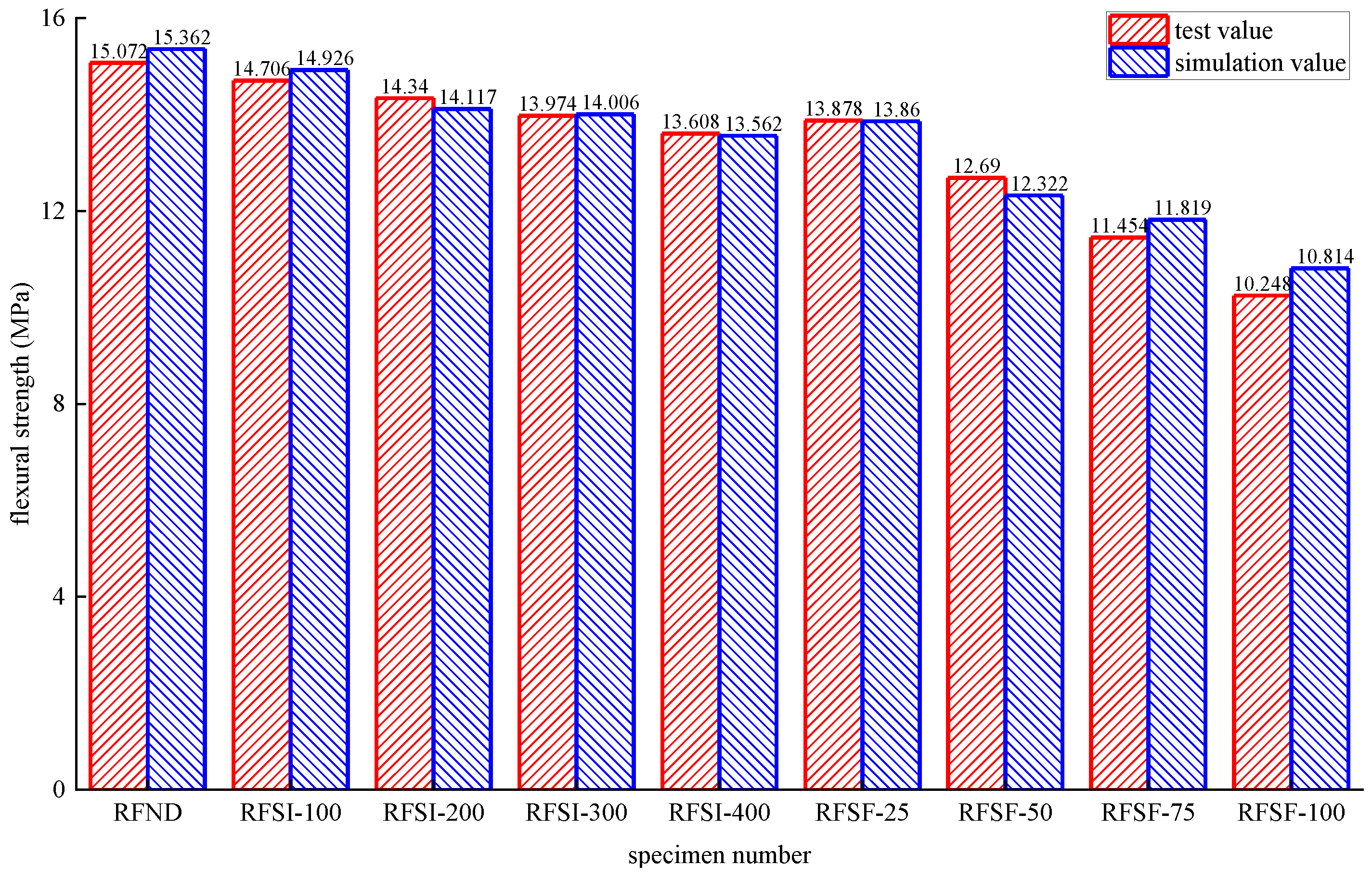
Figure 44.
Test values and simulated values of flexural strength of reinforced concrete flexural specimen.
Figure 44.
Test values and simulated values of flexural strength of reinforced concrete flexural specimen.
Table 1.
Tensile properties of CFRP and epoxy adhesive.
Table 1.
Tensile properties of CFRP and epoxy adhesive.
| Material | Tensile Strength/MPa | Elastic Modulus/GPa | Elongation at Break/% |
|---|
| CFRP composite | 3520 | 267 | 1.78 |
| Epoxy resin adhesive | 54.3 | 2.7 | 2.25 |
Table 2.
Concrete mix proportion.
Table 2.
Concrete mix proportion.
| Material | Water | Cement | Sand | Crushed Stone |
|---|
| content/(kg/m3) | 209 | 387 | 635 | 1169 |
Table 3.
Number of epoxy resin and CFRP sheet.
Table 3.
Number of epoxy resin and CFRP sheet.
| Exposure Environment | Epoxy Resin Adhesive Sheet | CFRP Sheet |
|---|
| No deterioration | EPND | CFRPND |
| Chlorine salt immersion for 100 h | EPSI-100 | CFRPSI-100 |
| Chlorine salt immersion for 200 h | EPSI-200 | CFRPSI-200 |
| Chlorine salt immersion for 300 h | EPSI-300 | CFRPSI-300 |
| Chlorine salt immersion for 400 h | EPSI-400 | CFRPSI-400 |
| Salt-freezing coupling 25 times | EPSF-25 | CFRPSF-25 |
| Salt-freezing coupling 50 times | EPSF-50 | CFRPSF-50 |
| Salt-freezing coupling 75 times | EPSF-75 | CFRPSF-75 |
| Salt-freezing coupling 100 times | EPSF-100 | CFRPSF-100 |
Table 4.
Number of concrete specimens.
Table 4.
Number of concrete specimens.
| Exposure Environment | Unreinforced Specimen | Reinforced Specimen |
|---|
| No deterioration | URFND | RFND |
| Chlorine salt immersion for 100 h | URFSI-100 | RFSI-100 |
| Chlorine salt immersion for 200 h | URFSI-200 | RFSI-200 |
| Chlorine salt immersion for 300 h | URFSI-300 | RFSI-300 |
| Chlorine salt immersion for 400 h | URFSI-400 | RFSI-400 |
| Salt-freezing coupling 25 times | URFSF-25 | RFSF-25 |
| Salt-freezing coupling 50 times | URFSF-50 | RFSF-50 |
| Salt-freezing coupling 75 times | URFSF-75 | RFSF-75 |
| Salt-freezing coupling 100 times | URFSF-100 | RFSF-100 |
Table 5.
Tensile strength of epoxy resin and CFRP sheet.
Table 5.
Tensile strength of epoxy resin and CFRP sheet.
| Epoxy Resin Adhesive Sheet | Tensile Strength/MPa | Change Rate/% | CFRP Sheet | Tensile Strength/MPa | Change Rate/% |
|---|
| EPND | 44.68 | — | CFRPND | 3508.98 | — |
| EPSI-100 | 44.34 | −0.76 | CFRPSI-100 | 3493.25 | −0.45 |
| EPSI-200 | 43.98 | −1.57 | CFRPSI-200 | 3479.37 | −0.84 |
| EPSI-300 | 43.66 | −2.28 | CFRPSI-300 | 3462.75 | −1.32 |
| EPSI-400 | 43.32 | −3.04 | CFRPSI-400 | 3448.31 | −1.73 |
| EPSF-25 | 43.24 | −3.22 | CFRPSF-25 | 3478.75 | −0.86 |
| EPSF-50 | 41.72 | −6.62 | CFRPSF-50 | 3450.09 | −1.68 |
| EPSF-75 | 40.33 | −9.74 | CFRPSF-75 | 3417.86 | −2.6 |
| EPSF-100 | 38.82 | −13.12 | CFRPSF-100 | 3387.57 | −3.46 |
Table 6.
Tensile strain of epoxy resin and CFRP sheet.
Table 6.
Tensile strain of epoxy resin and CFRP sheet.
| Epoxy Resin Adhesive Sheet | Tensile Strain/με | Change Rate/% | CFRP Sheet | Tensile Strain/με | Change Rate/% |
|---|
| EPND | 15,992 | — | CFRPND | 13,616 | — |
| EPSI-100 | 16,402 | 2.56 | CFRPSI-100 | 13,703 | 0.64 |
| EPSI-200 | 16,499 | 3.17 | CFRPSI-200 | 13,778 | 1.19 |
| EPSI-300 | 16,811 | 5.12 | CFRPSI-300 | 13,868 | 1.85 |
| EPSI-400 | 17,046 | 6.59 | CFRPSI-400 | 13,954 | 2.48 |
| EPSF-25 | 16,602 | 3.81 | CFRPSF-25 | 13,740 | 0.91 |
| EPSF-50 | 17,614 | 10.14 | CFRPSF-50 | 13,847 | 1.7 |
| EPSF-75 | 18,205 | 13.84 | CFRPSF-75 | 13,972 | 2.61 |
| EPSF-100 | 18,883 | 18.08 | CFRPSF-100 | 14,095 | 3.52 |
Table 7.
Tensile modulus of elasticity of epoxy resin and CFRP sheet.
Table 7.
Tensile modulus of elasticity of epoxy resin and CFRP sheet.
| Epoxy Resin Adhesive Sheet | Tensile Modulus of Elasticity/MPa | Change Rate/% | CFRP Sheet | Tensile Modulus of Elasticity/MPa | Change Rate/% |
|---|
| EPND | 2554 | — | CFRPND | 256,622 | — |
| EPSI-100 | 2482 | −2.82 | CFRPSI-100 | 256,122 | −0.19 |
| EPSI-200 | 2474 | −3.13 | CFRPSI-200 | 255,632 | −0.39 |
| EPSI-300 | 2421 | −5.21 | CFRPSI-300 | 253,048 | −1.39 |
| EPSI-400 | 2325 | −8.97 | CFRPSI-400 | 250,471 | −2.4 |
| EPSF-25 | 2455 | −3.88 | CFRPSF-25 | 254,066 | −1 |
| EPSF-50 | 2282 | −10.65 | CFRPSF-50 | 252,053 | −1.78 |
| EPSF-75 | 2048 | −19.81 | CFRPSF-75 | 248,353 | −3.22 |
| EPSF-100 | 1903 | −25.49 | CFRPSF-100 | 244,681 | −4.65 |
Table 8.
Flexural strength of concrete flexural specimen.
Table 8.
Flexural strength of concrete flexural specimen.
| Unreinforced Specimen | Flexural Strength/MPa | Change Rate/% | Reinforced Specimen | Flexural Strength/MPa | Change Rate/% |
|---|
| URFND | 3.804 | — | RFND | 15.072 | — |
| URFSI-100 | 3.582 | −5.836 | RFSI-100 | 14.706 | −2.428 |
| URFSI-200 | 3.366 | −11.514 | RFSI-200 | 14.34 | −4.857 |
| URFSI-300 | 3.252 | −14.511 | RFSI-300 | 13.974 | −7.285 |
| URFSI-400 | 3.006 | −20.978 | RFSI-400 | 13.608 | −9.713 |
| URFSF-25 | 3.144 | −17.35 | RFSF-25 | 13.878 | −7.922 |
| URFSF-50 | 2.556 | −32.808 | RFSF-50 | 12.69 | −15.804 |
| URFSF-75 | 1.908 | −49.842 | RFSF-75 | 11.454 | −24.005 |
| URFSF-100 | 1.302 | −65.773 | RFSF-100 | 10.248 | −32.006 |
Table 9.
Deflection of concrete flexural specimen.
Table 9.
Deflection of concrete flexural specimen.
| Unreinforced Specimen | Deflection/mm | Change Rate/% | Reinforced Specimen | Deflection/mm | Change Rate/% |
|---|
| URFND | 0.576 | — | RFND | 1.579 | — |
| URFSI-100 | 0.557 | −3.299 | RFSI-100 | 1.563 | −1.013 |
| URFSI-200 | 0.537 | −6.771 | RFSI-200 | 1.546 | −2.09 |
| URFSI-300 | 0.514 | −10.764 | RFSI-300 | 1.53 | −3.103 |
| URFSI-400 | 0.494 | −14.236 | RFSI-400 | 1.514 | −4.117 |
| URFSF-25 | 0.505 | −12.326 | RFSF-25 | 1.491 | −5.573 |
| URFSF-50 | 0.431 | −25.174 | RFSF-50 | 1.392 | −11.843 |
| URFSF-75 | 0.359 | −37.674 | RFSF-75 | 1.285 | −18.619 |
| URFSF-100 | 0.289 | −49.826 | RFSF-100 | 1.185 | −24.953 |


