
Structural Performance of Lightweight Aggregate Concrete Reinforced by Glass or Basalt Fiber Reinforced Polymer Bars

 ,
,  ,
, 
Abstract
:1. Introduction
2. Materials and Methods
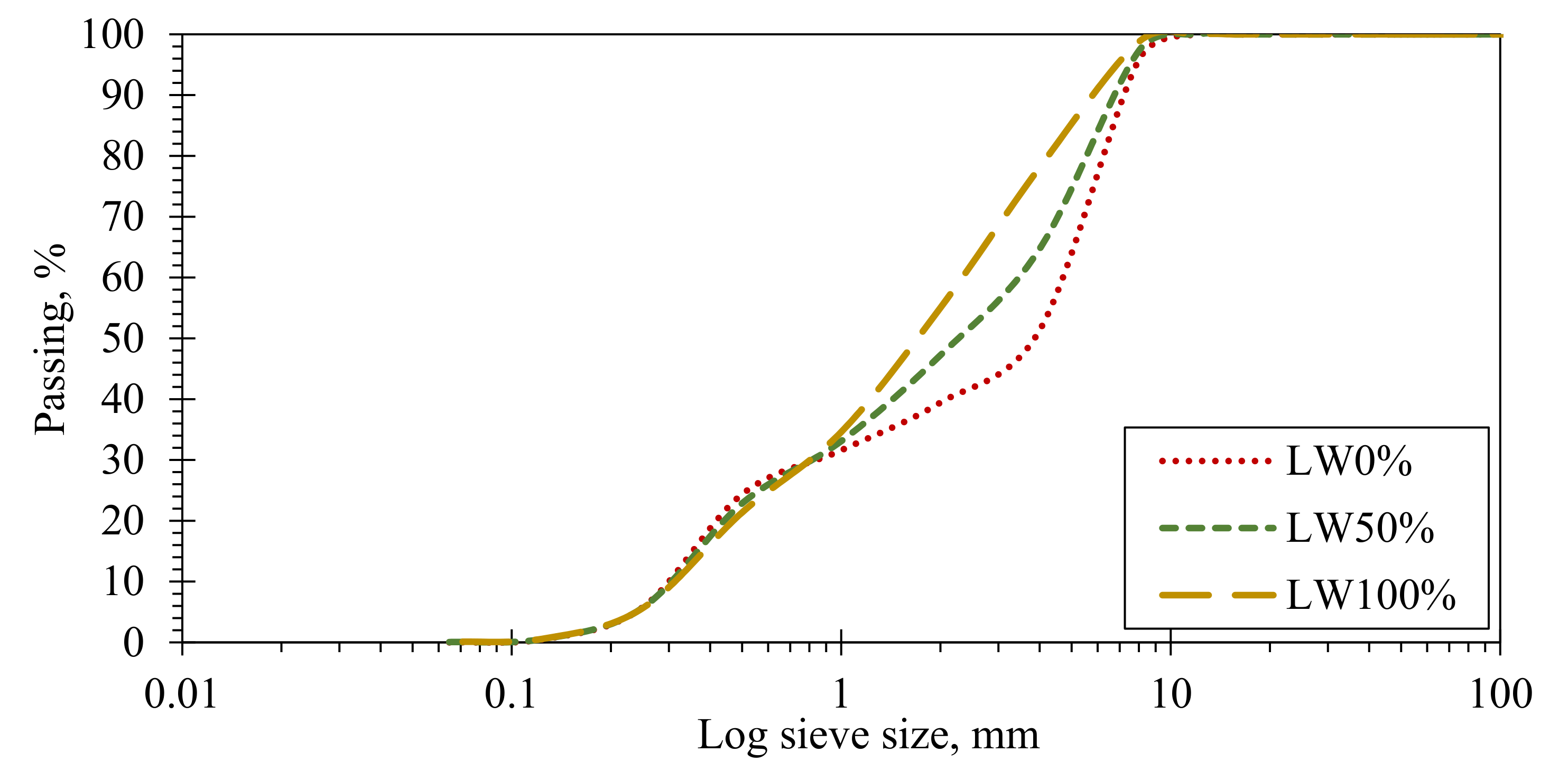
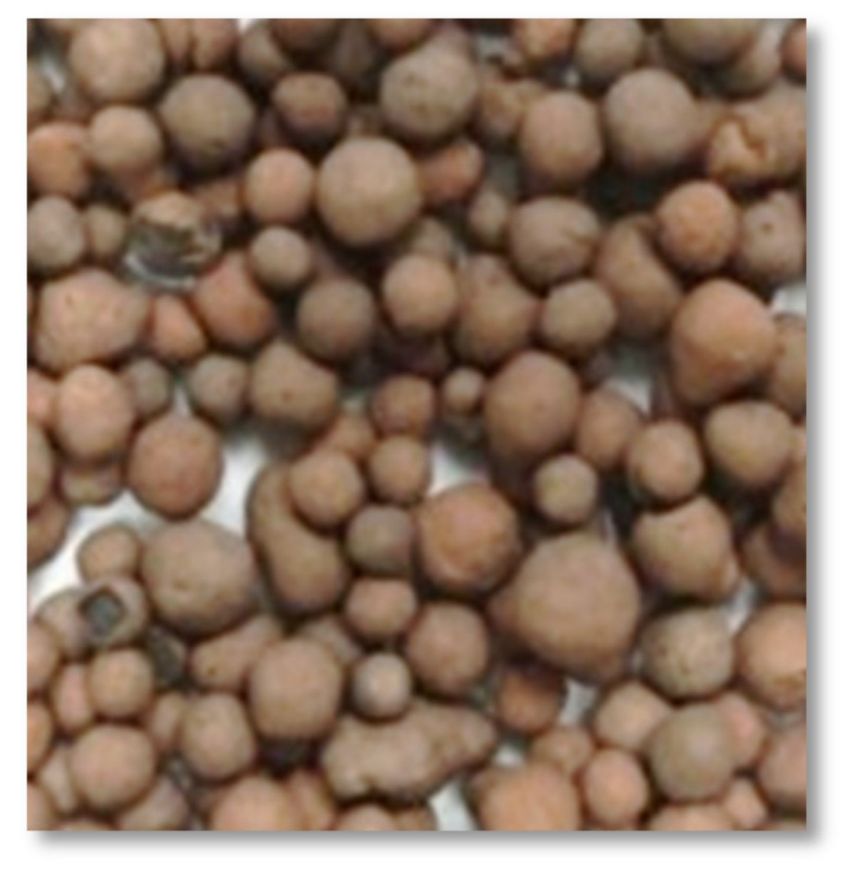
2.1. Materials
2.2. Mix Design
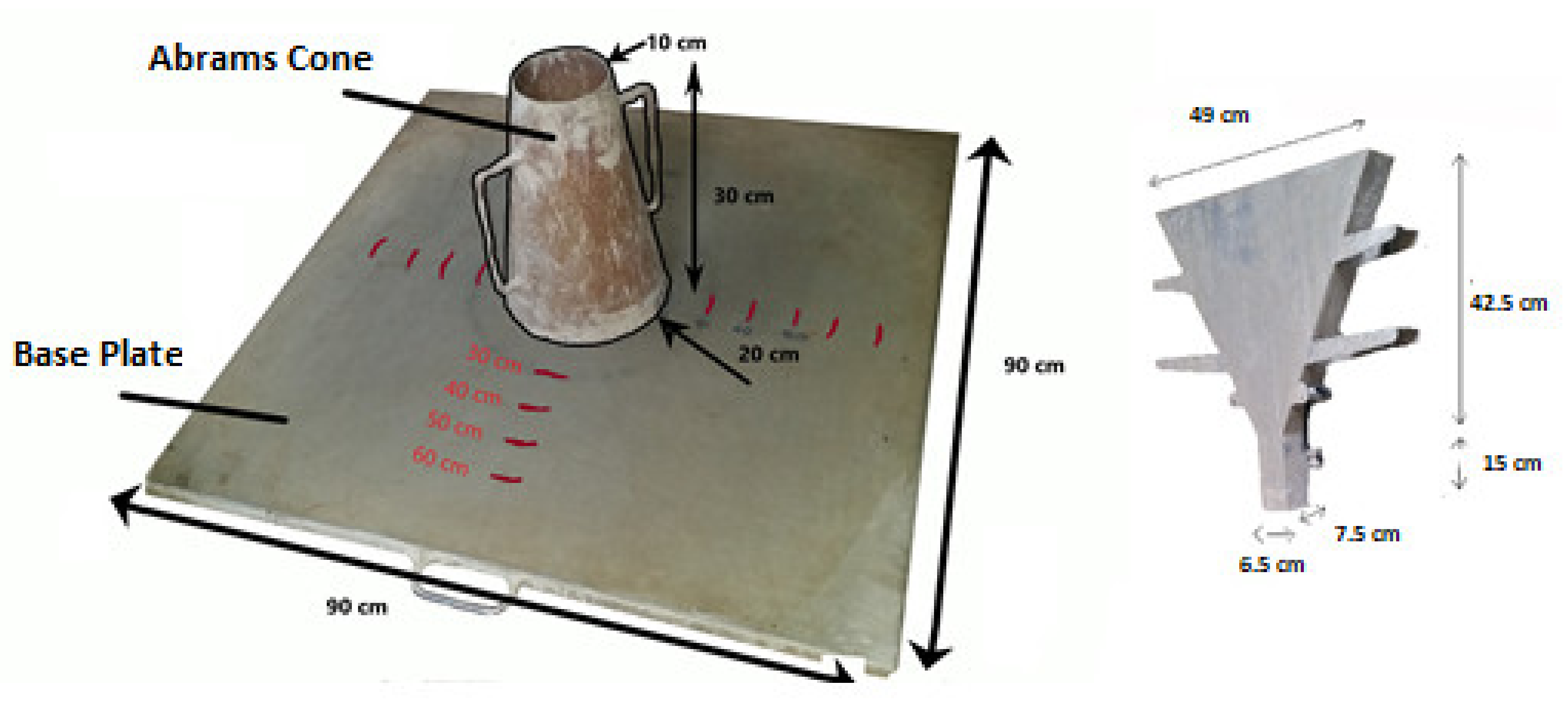
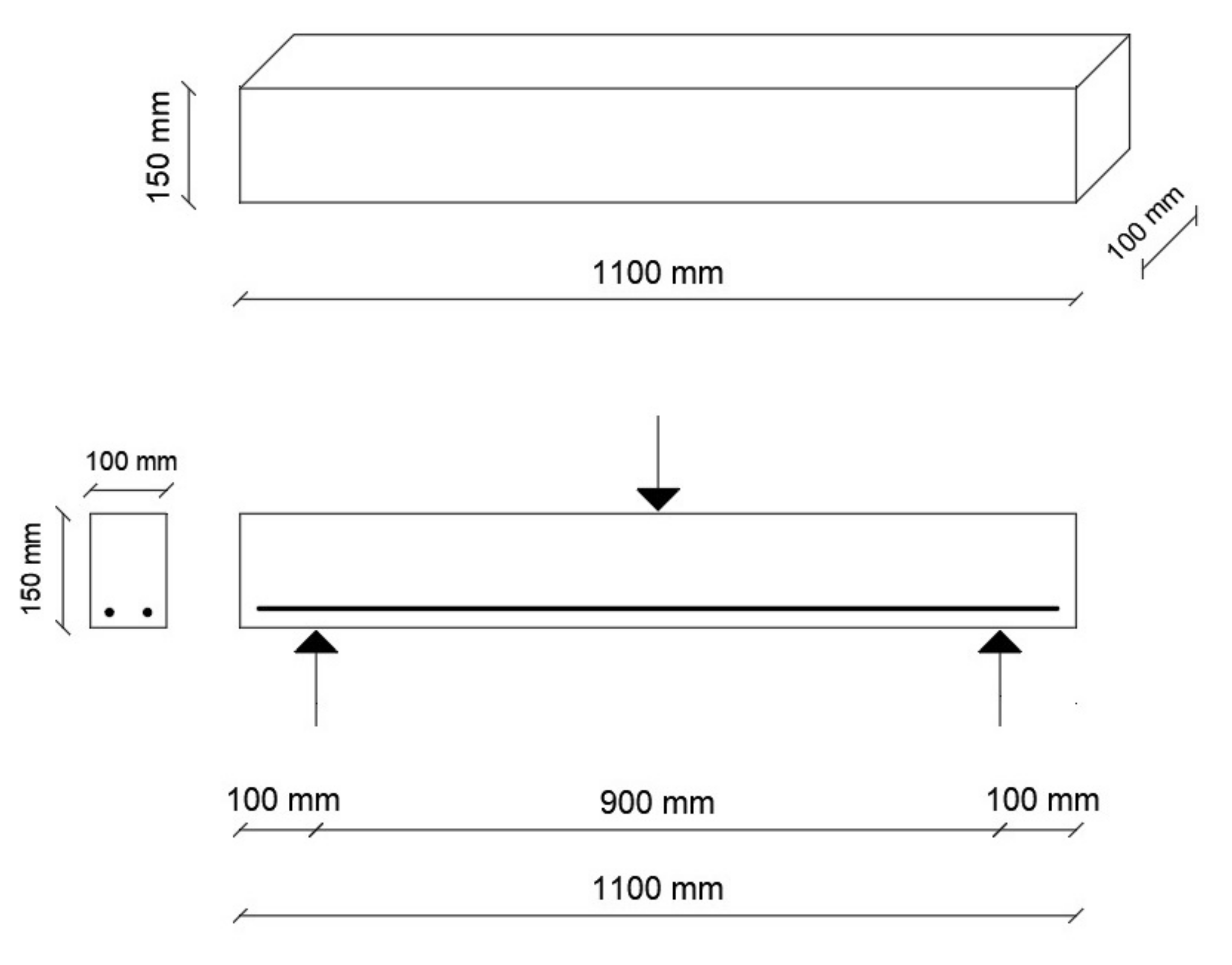
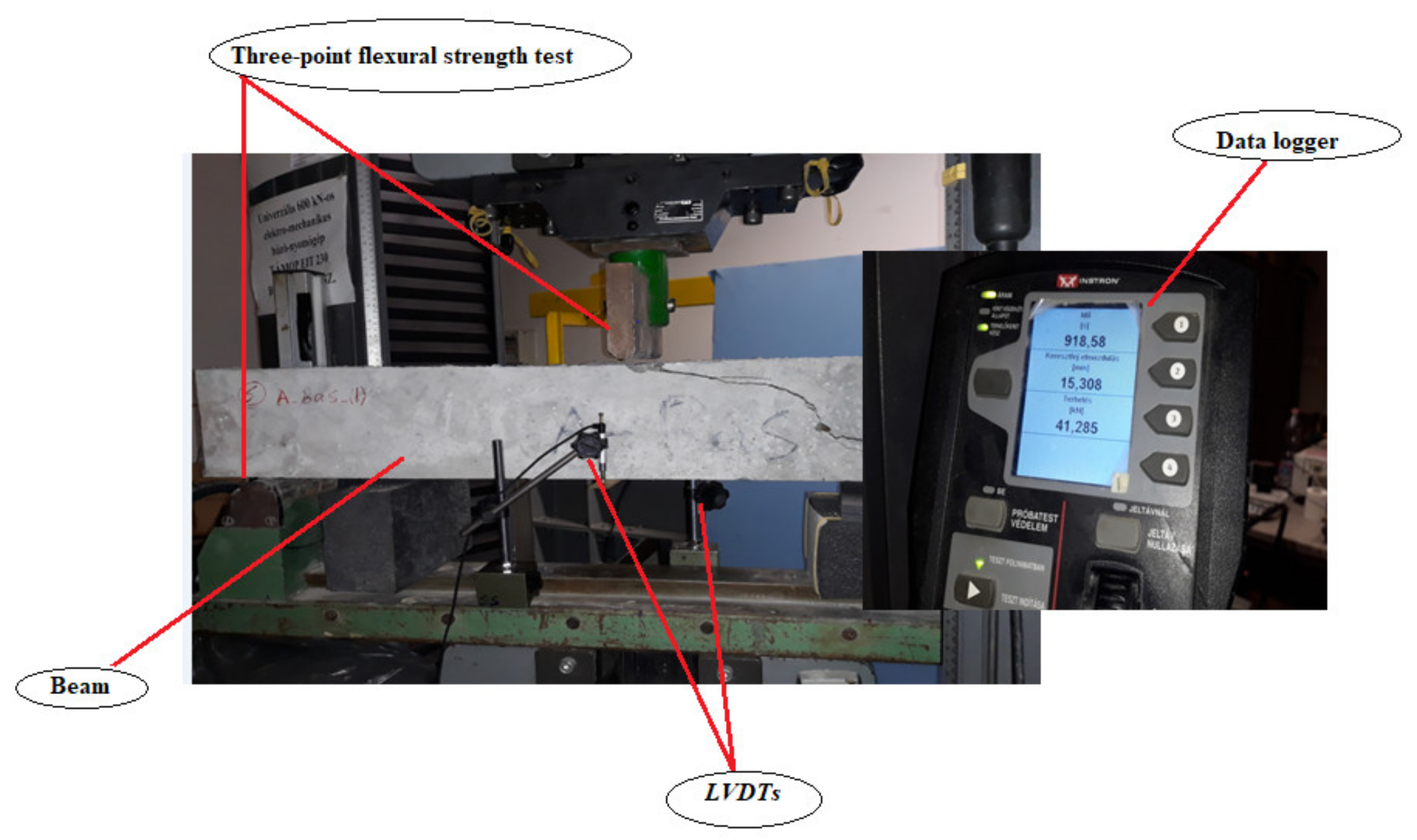
2.3. Test Setups and Specimen Preparation
- β1—0.65 (for high strength concrete).
- ffu—design tensile strength of the reinforcement bars (MPa).
- Ef—modulus of elasticity of the reinforcement bars (MPa).
- εcu—ultimate strain of the concrete.
- fc’—specified compressive strength of the concrete.
- b—width of the beam.
- d—distance from extreme fiber in compression to the center of reinforcement (mm).
- Af—area of longitudinal reinforcement (mm2).
3. Results and Discussion
3.1. Physical–Mechanical Properties of LWC
3.2. Behavior of Reinforced LWC Beams
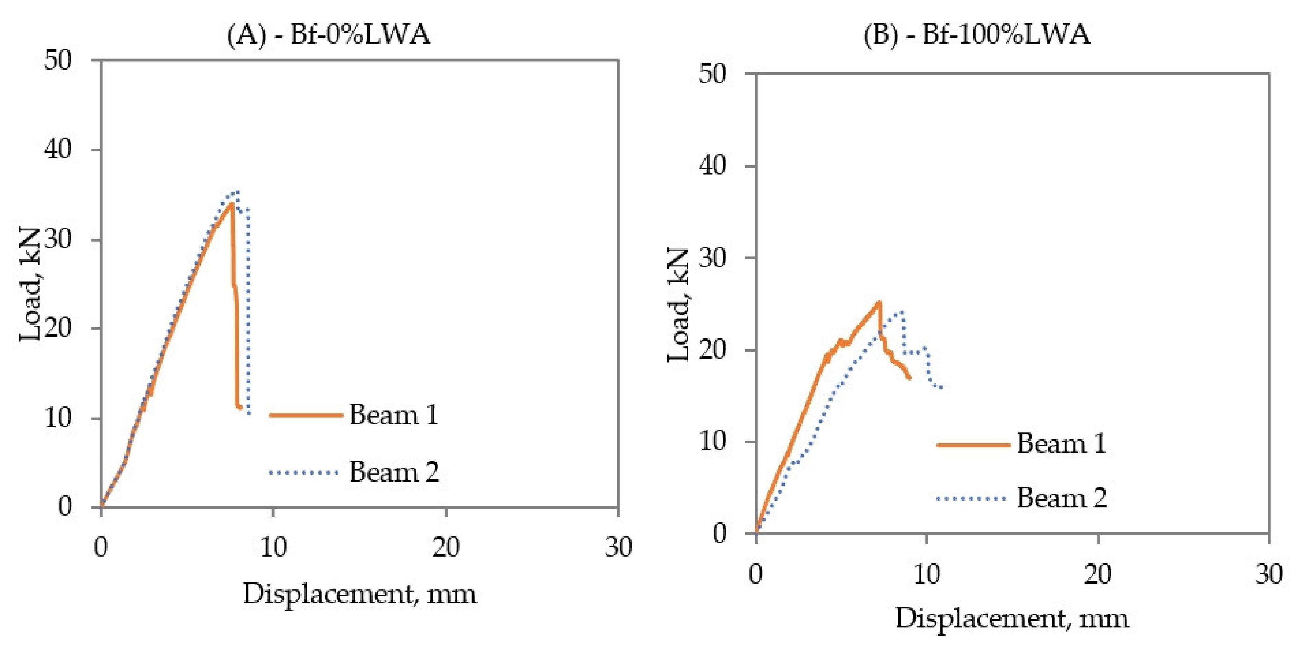
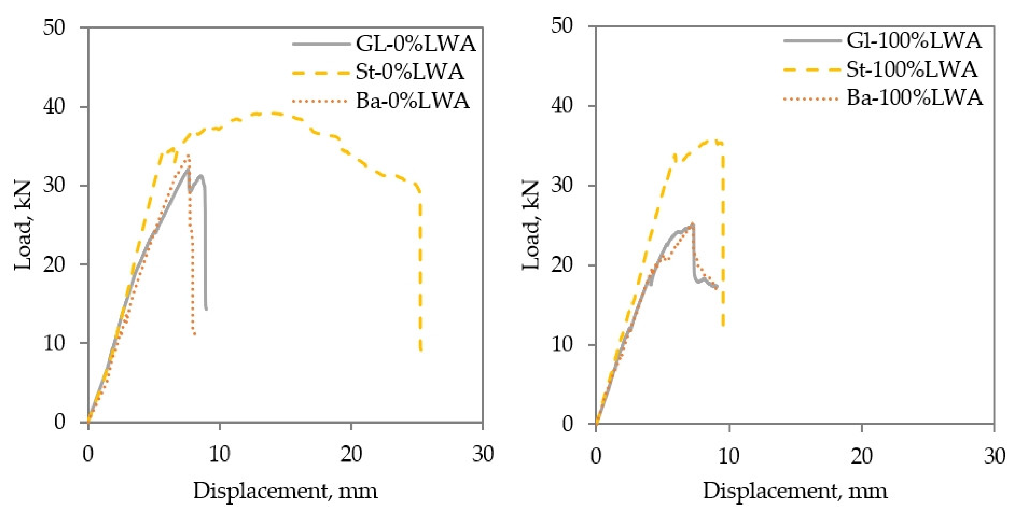
3.3. Load–Displacement Relationships
3.4. Cracking Moment (Mcr)
- Mcr—first cracking moment.
- λ—(= 0.75) modification factor reflecting the reduced mechanical properties of LWC, and λ = 1.0 for normal weight concrete.
- Ig—moment of inertia of the gross section.
- Yt—distance from the centroid axis of the gross section, neglecting reinforcement, to the tension face.
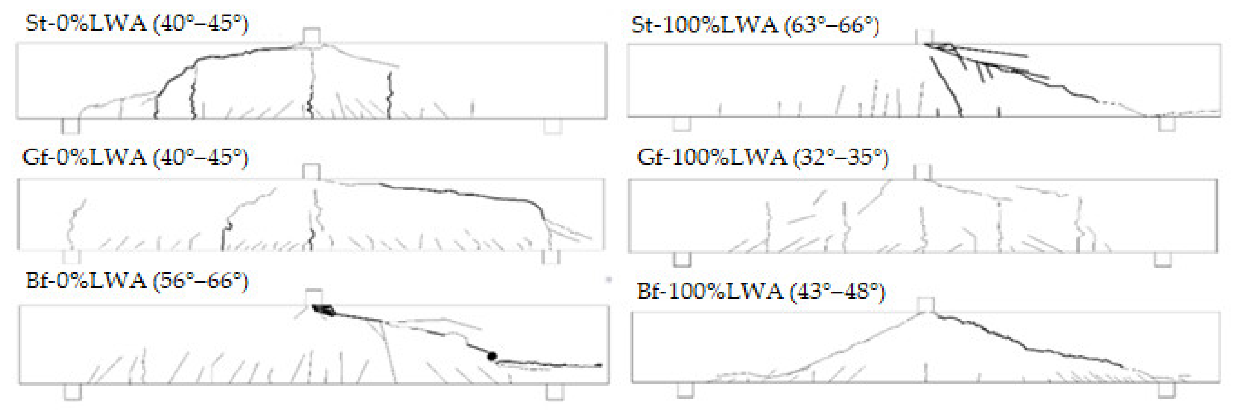
3.5. Crack’s Pattern and Width
4. Conclusions
- Fresh- and hardened-state physical and mechanical properties of SCC decreased by increasing the dose of expanded clay LWA.
- By using GFRP or BFRP bars, the maximum load and maximum deflection of beams are reduced compared to the beams reinforced with steel bars. However, in LWC, the effect of FRPs on the maximum deflection is smaller compared with the effect in normal weight concrete or LWC beams reinforced with steel bars.
- For LWC, the beams reinforced by GFRP or BFRP perform similarly in terms of maximum load, maximum deflection, crack width, and cracking moment. The maximum deflection of the beams reinforced by steel bars is decreased when LWC is used.
Author Contributions
Funding
Institutional Review Board Statement
Informed Consent Statement
Data Availability Statement
Acknowledgments
Conflicts of Interest
References
- Abed, M.A.; Alkurdi, Z.; Kheshfeh, A.; Kovács, T.; Nehme, S. Numerical Evaluation of Bond Behavior of Ribbed Steel Bars or Seven-wire Strands Embedded in Lightweight Concrete. Period. Polytech.-Civ. Eng. 2021, 65, 385–396. [Google Scholar] [CrossRef]
- Skapa, S.; Vochozka, M. Techno-economic considerations: Turning fermentation residues into lightweight concrete. Energy Sources Part A-Recovery Util. Environ. Eff. 2019, 41, 1041–1048. [Google Scholar] [CrossRef]
- Napolano, L.; Menna, C.; Graziano, S.F.; Asprone, D.; D’Amore, M.; de Gennaro, R.; Dondi, M. Environmental life cycle assessment of lightweight concrete to support recycled materials selection for sustainable design. Constr. Build. Mater. 2016, 119, 370–384. [Google Scholar] [CrossRef]
- Ahn, Y.B.; Jang, J.G.; Lee, H.K. Mechanical properties of lightweight concrete made with coal ashes after exposure to elevated temperatures. Cem. Concr. Compos. 2016, 72, 27–38. [Google Scholar] [CrossRef]
- Nemes, R.; Abed, M.A.; Seyam, A.M.; Lublóy, É. Behavior of structural lightweight concrete produced with expanded clay aggregate and after exposure to high temperatures. J. Therm. Anal. Calorim. 2021. [Google Scholar] [CrossRef]
- Hedjazi, S. Compressive Strength of Lightweight Concrete. In Compressive Strength of Concrete; IntechOpen: London, UK, 2020; pp. 1–18. [Google Scholar] [CrossRef] [Green Version]
- Purnomo, H.; Putri, R.K.; Perdani, P. Splitting tensile strength of lightweight concrete using polypropylene coarse aggregate coated with sand. IOP Conf. Ser. Mater. Sci. Eng. 2019, 625, 012008. [Google Scholar] [CrossRef]
- Nahhab, A.H.; Ketab, A.K. Influence of content and maximum size of light expanded clay aggregate on the fresh, strength, and durability properties of self-compacting lightweight concrete reinforced with micro steel fibers. Constr. Build. Mater. 2020, 233, 117922. [Google Scholar] [CrossRef]
- Bogas, J.A.; Nogueira, R. Tensile strength of structural expanded clay lightweight concrete subjected to different curing conditions. Ksce J. Civ. Eng. 2014, 18, 1780–1791. [Google Scholar] [CrossRef]
- Sneed, L.H.; Krc, K.; Wermager, S.; Meinheit, D. Interface shear transfer of lightweight-aggregate concretes with different lightweight aggregates. PCI J. 2016, 61, 38–55. [Google Scholar] [CrossRef]
- Hora, M. Temperature analysis of lightweight aggregate concrete slab members at elevated temperatures for predicting fire resistance. Appl. Struct. Fire Eng. 2013, 19–20. [Google Scholar]
- Lo, Y.; Gao, X.F.; Jeary, A.P. Microstructure of pre-wetted aggregate on lightweight concrete. Build. Environ. 1999, 34, 759–764. [Google Scholar] [CrossRef]
- Pla, C.; Tenza-Abril, A.J.; Valdes-Abellan, J.; Benavente, D. Influence of microstructure on fluid transport and mechanical properties in structural concrete produced with lightweight clay aggregates. Constr. Build. Mater. 2018, 171, 388–396. [Google Scholar] [CrossRef]
- Zukri, A.; Nazir, R.; Said, K.N.M.; Moayedi, H. Physical and Mechanical Properties of Lightweight Expanded Clay Aggregate (LECA). In Proceedings of the 12th International Civil Engineering Post Graduate Conference (SEPKA)/3rd International Symposium on Expertise of Engineering Design (ISEED), Johor, Malaysia, 27–28 August 2018; Volume 250. [Google Scholar] [CrossRef] [Green Version]
- Sonia, T.; Subashini, R. Experimental Investigation on Mechanical Properties of Light Weight Concrete Using Leca. IJSR 2015, 5, 4. [Google Scholar]
- Maghsoudi, A.A.; Mohamadpour, S.; Maghsoudi, M. Mix design and mechanical properties of self compacting light weight concrete. Int. J. Civ. Eng. 2011, 9, 230–236. [Google Scholar]
- Banawair, A.S.; Qaid, G.M.; Adil, Z.M.; Nasir, N.A.M. The strength of lightweight aggregate in concrete—A Review. IOP Conf. Ser. Earth Environ. Sci. 2019, 357, 012017. [Google Scholar] [CrossRef] [Green Version]
- Zhou, H.; Jia, B.; Zhang, P.; Li, J.; Huang, H. Achieve the effective connection of FRP bars by blocking resistance and adhesive Force: Adhesive-Bolt hybrid joint. Compos. Struct. 2022, 285, 115143. [Google Scholar] [CrossRef]
- Sneed, L.H.; Verre, S.; Ombres, L.; Carloni, C. Flexural behavior RC beams strengthened and repaired with SRP composite. Eng. Struct. 2022, 258, 114084. [Google Scholar] [CrossRef]
- Abed, M.A.; Alkurdi, Z.; Fořt, J.; Černý, R.; Solyom, S. Bond Behavior of FRP Bars in Lightweight SCC under Direct Pull-Out Conditions: Experimental and Numerical Investigation. Materials 2022, 15, 3555. [Google Scholar] [CrossRef]
- Balcıoğlu, E.H.; Sarikaya, H. The Effect of Glass Fiber Rebar Reinforcement on Flexural Behaviour of Reinforced Concrete Structural Elements. 2018. Available online: https://www.researchgate.net/publication/328809238 (accessed on 6 September 2018).
- Liu, X.; Sun, Y.J.; Wu, T.; Liu, Y. Flexural cracks in steel fiber-reinforced lightweight aggregate concrete beams reinforced with FRP bars. Compos. Struct. 2020, 253, 112752. [Google Scholar] [CrossRef]
- Ye, Y.; Zhuge, Y.; Smith, S.T.; Zeng, J.; Bai, Y. Behavior of GFRP-RC columns under axial compression: Assessment of existing models and a new axial load-strain model. J. Build. Eng. 2022, 47, 103782. [Google Scholar] [CrossRef]
- Raj, S.; Kumar, V.R.; Kumar, B.H.B.; Iyer, N.R. Basalt: Structural insight as a construction material. Sadhana-Acad. Proc. Eng. Sci. 2017, 42, 75–84. [Google Scholar] [CrossRef] [Green Version]
- Jabbar, S.A.A.; Farid, S.B.H. Replacement of steel rebars by GFRP rebars in the concrete structures. Karbala Int. J. Mod. Sci. 2018, 4, 216–227. [Google Scholar] [CrossRef]
- Pantelides, C.P.; Besser, B.T.; Liu, R.F. One-Way Shear Behavior of Lightweight Concrete Panels Reinforced with GFRP Bars. J. Compos. Constr. 2012, 16, 2–9. [Google Scholar] [CrossRef]
- Abbood, I.S.; Odaa, S.A.; Hasan, K.F.; Jasimd, M.A. Properties evaluation of fiber reinforced polymers and their constituent materials used in structures—A review. Mater. Today Proc. 2021, 43, 1003–1008. [Google Scholar] [CrossRef]
- El Refai, A.; Abed, F. Concrete Contribution to Shear Strength of Beams Reinforced with Basalt Fiber-Reinforced Bars. J. Compos. Constr. 2016, 20, 0000648. [Google Scholar] [CrossRef]
- Elgabbas, F.; Vincent, P.; Ahmed, E.A.; Benmokrane, B. Experimental testing of basalt-fiber-reinforced polymer bars in concrete beams. Compos. Part B-Eng. 2016, 91, 205–218. [Google Scholar] [CrossRef]
- ACI 440.1R-15; Guide for the Design and Construction of Structural Concrete Reinforced with Fibre-Reinforced Polymer (FRP) Bars. American Concrete Institute: Farmington Hills, MI, USA, 2015. Available online: www.concrete.org (accessed on 6 March 2015).
- CSA S806-02; Design and Construction of Building Components with Fibre-Reinforced Polymers. Canadian Standards Association: Toronto, ON, Canada, 2012.
- BS EN 196-2; Method of Testing Cement, Chemical Analysis of Cement. BSI: London, UK, 2013.
- EFNARC. The European Guidelines for Self-Compacting Concrete. May 2005. Available online: https://www.theconcreteinitiative.eu/images/ECP_Documents/EuropeanGuidelinesSelfCompactingConcrete.pdf (accessed on 5 May 2015).
- BS EN 12390-3; Testing Hardened Concrete, Compressive Strength of Test Specimens. BSI: London, UK, 2009.
- CEN EN 12697-23; Bituminous Mixtures, Test Methods for Hot Mix Asphalt. Part 23: Determination of the Indirect Tensile Strength of Bituminous Specimens. CEN: Brussels, Belgium, 2004.
- BS EN 12390-5; Testing Hardened Concrete, Flexural Strength of Test Specimens. BSI: London, UK, 2009.
- Abed, M.; Nemes, R. Fresh properties of the selfcompacting high-performance concrete using recycled concrete aggregate. Építöanyag 2019, 71, 18–23. [Google Scholar] [CrossRef]
- Eurocode 2-BS EN 1992-1-1; General Rules and Rules for Buildings. BSI: London, UK, 1992.
- Vargas, P.; Restrepo-Baena, O.; Tobon, J.I. Microstructural analysis of interfacial transition zone (ITZ) and its impact on the compressive strength of lightweight concretes. Constr. Build. Mater. 2017, 137, 381–389. [Google Scholar] [CrossRef]
- Carrillo, J.; Lizarazo, J.M.; Bonett, R. Effect of lightweight and low-strength concrete on seismic performance of thin lightly-reinforced shear walls. Eng. Struct. 2015, 93, 61–69. [Google Scholar] [CrossRef]
- Junaid, M.T.; Elbana, A.; Altoubat, S.; Al-Sadoon, Z. Experimental study on the effect of matrix on the flexural behavior of beams reinforced with Glass Fiber Reinforced Polymer (GFRP) bars. Compos. Struct. 2019, 222, 110930. [Google Scholar] [CrossRef]
- Urbanski, M.; Lapko, A.; Garbacz, A. Investigation on Concrete Beams Reinforced with Basalt Rebars as an Effective Alternative of Conventional R/C Structures. Mod. Build. Mater. Struct. Tech. 2013, 57, 1183–1191. [Google Scholar] [CrossRef] [Green Version]
- Bengar, H.A.; Zarrinkolaei, F.A.; Bozorgnasab, M. Shear Capacity of Lightweight Concrete Beam Reinforced with Glass Fiber-Reinforced Polymer Bars. Iran. J. Sci. Technol.-Trans. Civ. Eng. 2021, 45, 1565–1574. [Google Scholar] [CrossRef]


| Measured Property of CEM I | ||||||||||||
|---|---|---|---|---|---|---|---|---|---|---|---|---|
| Density (g/cm3) | Specific Surface Area (cm2/g) | Loss on Ignition (%) | Chloride (%) | Free CaO (%) | SiO2 (%) | CaO (%) | MgO (%) | Fe2O3 (%) | Al2O3 (%) | SO3 (%) | Na2O (%) | K2O (%) |
| 3.02 | 3326 | 3 | 0.04 | 0.71 | 19.33 | 63.43 | 1.45 | 3.42 | 4.67 | 2.6 | 0.33 | 0.78 |
| Property | Expanded Clay |
|---|---|
| Oven-dry density (kg/m3) | 2620 |
| Bulk density (kg/m3) | 359 |
| Particle density (kg/m3) | 650 |
| Water absorption (%) | 18.3 |
| Particle porosity (%) | 75.2 |
| Crushing resistance (MPa) | 2 |
| Property | Tensile Strength (MPa) | Yield Strength (MPa) | Modulus of Elasticity (MPa) | Ultimate Strain (%) | Density (kg/m3) | Diameter (mm) | - |
|---|---|---|---|---|---|---|---|
| Steel B500B | 540 | 500 | 200,000 | 5 | 7850 | 8 | 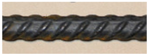 |
| GFRP | 920 | - | 55,500 | 1.68 | 2100 | 10 |  |
| BFRP | 1100 | - | 70,000 | 2.2 | 1900 | 14 |  |
| Mix | Proportions in kg/m3 | ||||||
|---|---|---|---|---|---|---|---|
| Cement | Fine Aggregate | Coarse Aggregate | Glenium C300 | Glenium 51 | Water | ||
| Natural Sand | NA | LWA | |||||
| 0/4 (mm) | 4/8 (mm) | ||||||
| LW0% | 500 | 785 | 960 | – | 0.75 | 0.75 | 175 |
| LW50% | 500 | 785 | 480 | 232 | 1.50 | 2.00 | 175 |
| LW100% | 500 | 785 | – | 464 | 2.25 | 3.75 | 175 |
| Test | Formula | Notations |
|---|---|---|
| Compressive strength | P = load at failure (kN) Ac = compression area (mm2) LT = length of the cylinder (mm) D = diameter of the cylinder (mm) b = width of the prism (mm) d = depth of the prism (mm) LF = length between supports of the prism (mm) Ashear = shear area (mm2) | |
| Splitting tensile strength | ||
| Bending strength | ||
| Shear strength |
| Concrete Type | Beam Nomenclature | Beam No. | Reinforcing Material | Compressive Strength (MPa) | Span/Depth | Longitudinal Reinforcement | |||
|---|---|---|---|---|---|---|---|---|---|
| Amount of Reinforcement | ρf (%) | ρfb (%) | ρf/ρfb | ||||||
| Normal weight concrete | St-0%LWA | Beam 1 | Steel | 78 | 7.76 | 2 No. 8 | 0.87 | 3.21 | 0.27 |
| Beam 2 | |||||||||
| Bf-0%LWA | Beam 1 | BFRP | 7.96 | 2 No. 14 | 2.72 | 1.36 | 2.00 | ||
| Beam 2 | |||||||||
| Gf-0%LWA | Beam 1 | GFRP | 7.83 | 2 No. 10 | 1.37 | 0.70 | 1.95 | ||
| Beam 2 | |||||||||
| Lightweight concrete | St-100%LWA | Beam 1 | Steel | 56 | 7.76 | 2 No. 8 | 0.87 | 2.31 | 0.37 |
| Beam 2 | |||||||||
| Bf-100%LWA | Beam 1 | BFRP | 7.96 | 2 No. 14 | 2.72 | 0.98 | 2.78 | ||
| Beam 2 | |||||||||
| Gf-100%LWA | Beam 1 | GFRP | 7.83 | 2 No. 10 | 1.37 | 0.52 | 2.63 | ||
| Beam 2 | |||||||||
| Mix | Slump Flow (mm) | V-Funnel (s) | ρ (kg/m3) | fc (MPa) | fct,sp (MPa) | fct,fl (MPa) | τc (MPa) |
|---|---|---|---|---|---|---|---|
| LW0% | 670 | 7.0 | 2349 | 78.0 | 4.0 | 6.2 | 10.3 |
| LW50% | 635 | 6.7 | 2030 | 60.0 | 3.3 | 5.6 | 8.3 |
| LW100% | 620 | 6.0 | 1851 | 56.0 | 3.0 | 5.0 | 6.8 |
| Property | St-0%LWA | St-100%LWA | Bf-0%LWA | Bf-100%LWA | Gf-0%LWA | Gf-100%LWA |
|---|---|---|---|---|---|---|
| Max. load (kN) | 41.45 | 35.29 | 35.45 | 25.20 | 31.98 | 26.58 |
| Max. deflection (mm) | 13.49 | 9.36 | 7.86 | 7.26 | 7.59 | 7.51 |
| Beam | Experimental Mcr (kNm) | Calculated Mcr (kNm) | Mode of Failure |
|---|---|---|---|
| St-0%LWA | 2.99 | 2.05 | Reinforcement yielding and Concrete crushing |
| St-100%LWA | 2.22 | 1.30 | Reinforcement yielding and Concrete crushing |
| Gf-0%LWA | 2.07 | 2.05 | Concrete crushing |
| Gf-100%LWA | 1.57 | 1.30 | Concrete crushing |
| Bf-0%LWA | 2.05 | 2.05 | Concrete crushing |
| Bf-100%LWA | 1.33 | 1.30 | Concrete crushing |
| Property | St-0%LWA | St-100%LWA | Gf-0%LWA | Gf-100%LWA | Bf-0%LWA | Bf-100%LWA |
|---|---|---|---|---|---|---|
| Crack width at ultimate load (mm) | 1.9 | 1.7 | 0.6 | 0.1 | 0.3 | 0.2 |
Publisher’s Note: MDPI stays neutral with regard to jurisdictional claims in published maps and institutional affiliations. |
© 2022 by the authors. Licensee MDPI, Basel, Switzerland. This article is an open access article distributed under the terms and conditions of the Creative Commons Attribution (CC BY) license (https://creativecommons.org/licenses/by/4.0/).
Share and Cite
Abed, M.A.; Anagreh, A.; Tošić, N.; Alkhabbaz, O.; Alshwaiki, M.E.; Černý, R. Structural Performance of Lightweight Aggregate Concrete Reinforced by Glass or Basalt Fiber Reinforced Polymer Bars. Polymers 2022, 14, 2142. https://doi.org/10.3390/polym14112142
Abed MA, Anagreh A, Tošić N, Alkhabbaz O, Alshwaiki ME, Černý R. Structural Performance of Lightweight Aggregate Concrete Reinforced by Glass or Basalt Fiber Reinforced Polymer Bars. Polymers. 2022; 14(11):2142. https://doi.org/10.3390/polym14112142
Chicago/Turabian StyleAbed, Mohammed A., Aysha Anagreh, Nikola Tošić, Ola Alkhabbaz, Majd Eddin Alshwaiki, and Robert Černý. 2022. "Structural Performance of Lightweight Aggregate Concrete Reinforced by Glass or Basalt Fiber Reinforced Polymer Bars" Polymers 14, no. 11: 2142. https://doi.org/10.3390/polym14112142
APA StyleAbed, M. A., Anagreh, A., Tošić, N., Alkhabbaz, O., Alshwaiki, M. E., & Černý, R. (2022). Structural Performance of Lightweight Aggregate Concrete Reinforced by Glass or Basalt Fiber Reinforced Polymer Bars. Polymers, 14(11), 2142. https://doi.org/10.3390/polym14112142