
Preparation of the Flexible Green Body of YAG Ceramic Fiber by Melt Spinning

Abstract
:1. Introduction
2. Experimental Procedure
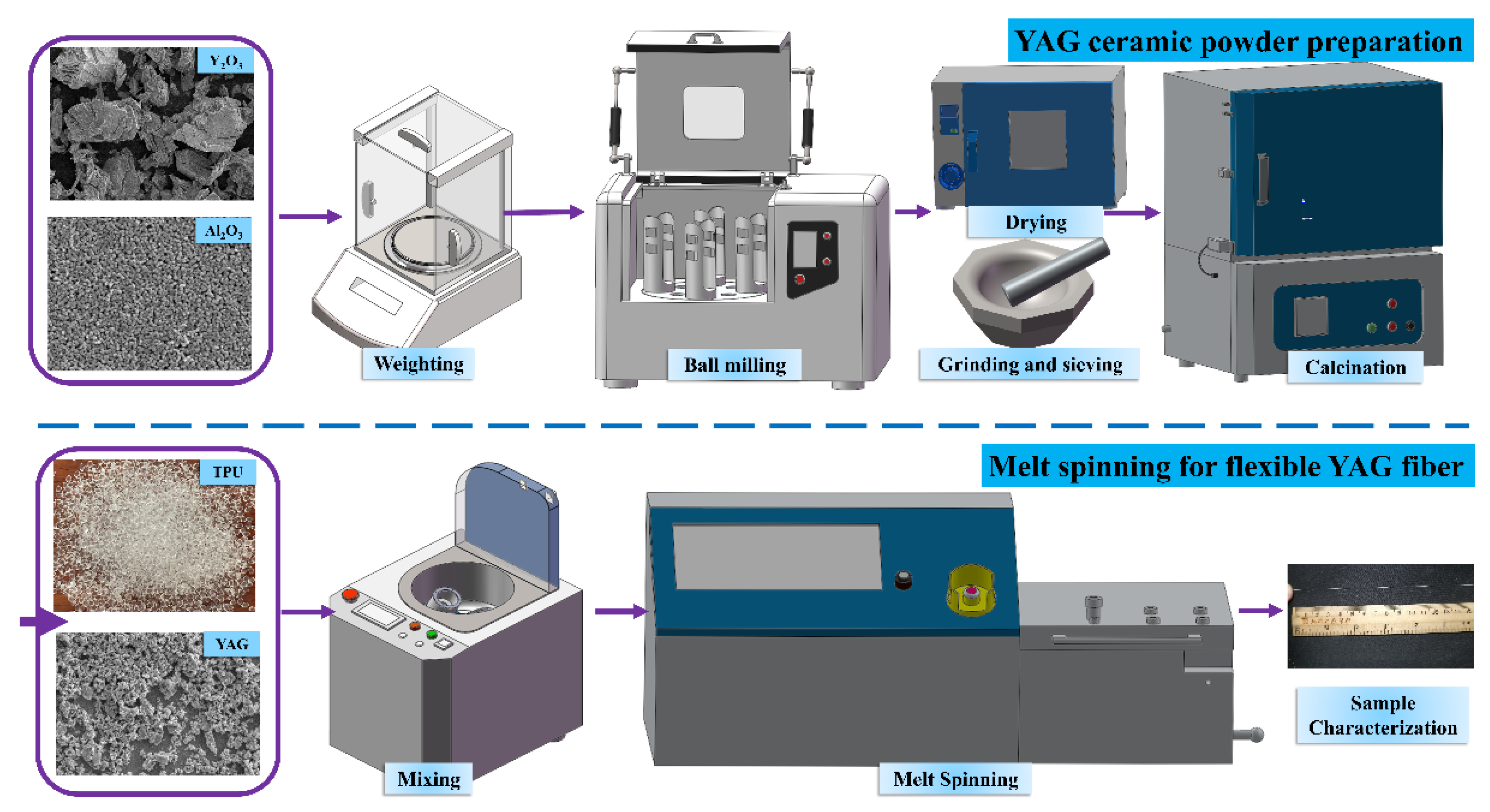
2.1. YAG Ceramic Powder Preparation
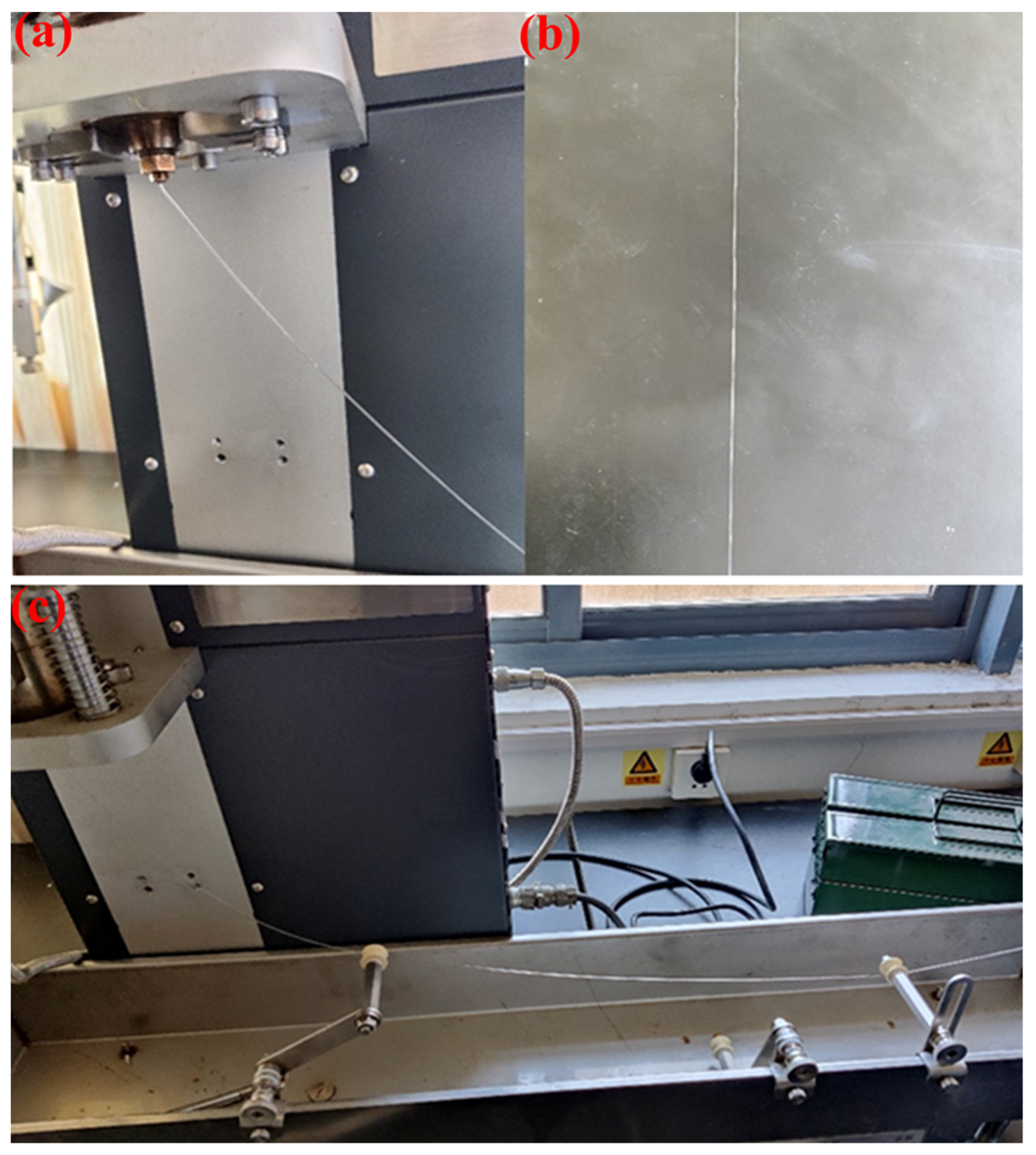
2.2. Melt Spinning for Flexible Green Body
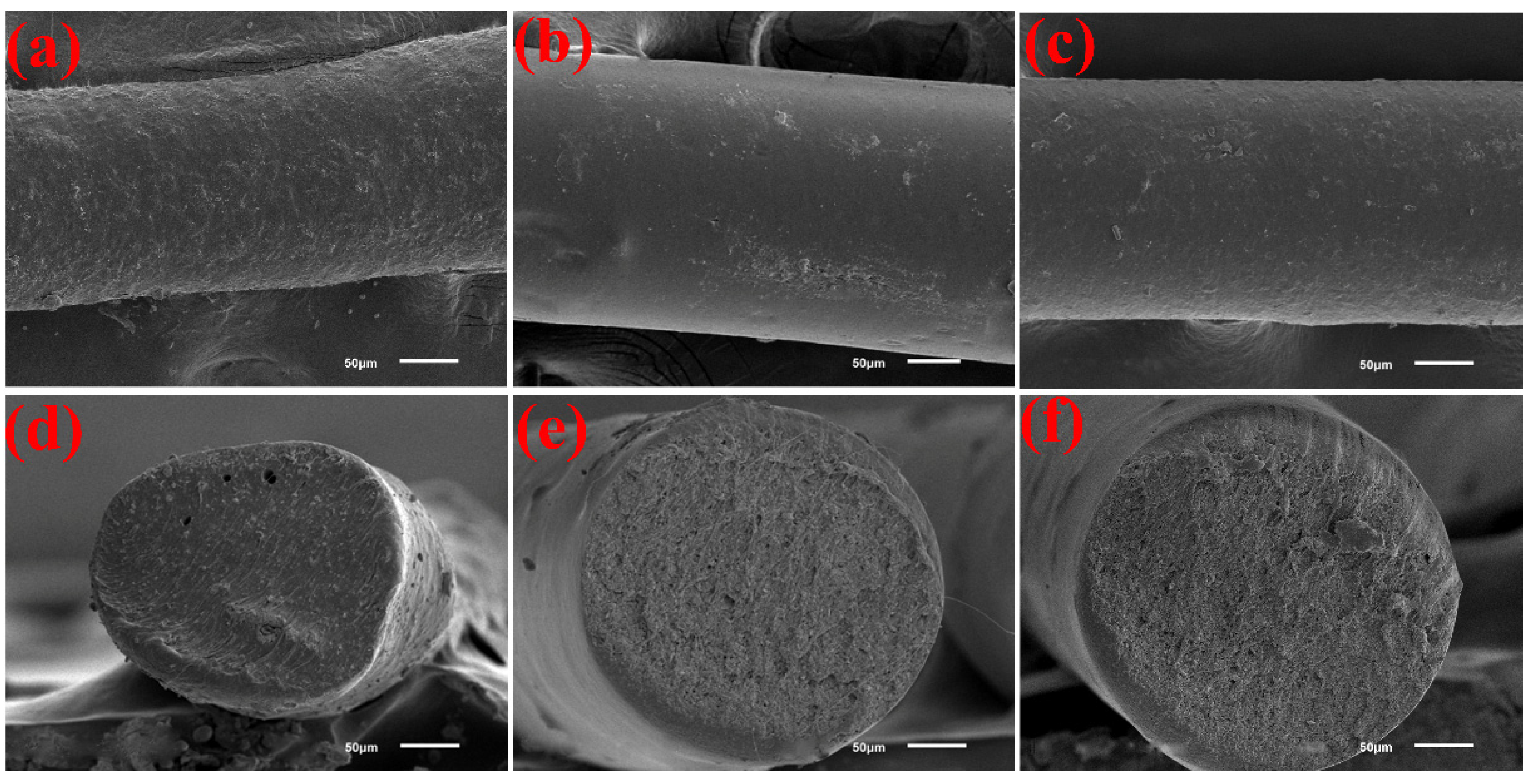
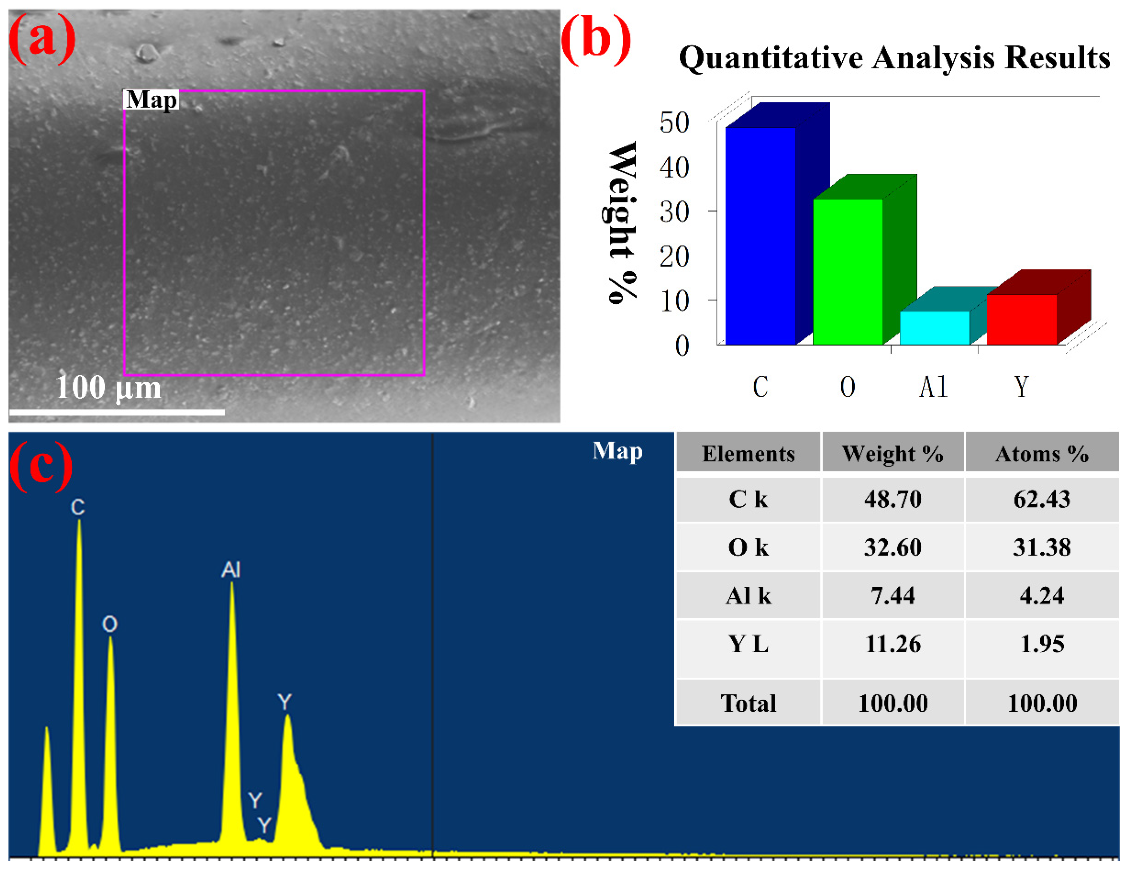
2.3. Characterizations
3. Results and Discussion
4. Conclusions
Author Contributions
Funding
Data Availability Statement
Acknowledgments
Conflicts of Interest
References
- Snitzer, E. Proposed Fiber Cavities for Optical Masers. J. Appl. Phys. 1961, 32, 36–39. [Google Scholar] [CrossRef]
- Thomas, G.A.; Shraiman, B.I.; Glodis, P.F.; Stephen, M.J. Towards the clarity limit in optical fibre. Nature 2000, 404, 262–264. [Google Scholar] [CrossRef] [PubMed]
- Fair, G.E.; Hay, R.S.; Lee, H.D.; Boakye, E.E.; Parthasarathy, T.A. Towards optical quality yttrium aluminum garnet (YAG) fibers: Recent efforts at AFRL/RX. Laser Technol. Déf. Secur. VII 2010, 7686, 76860E. [Google Scholar] [CrossRef]
- Wang, T.; Zhang, J.; Zhang, N.; Wu, B.; Wang, S.; Jia, Z.; Tao, X. Research Progress in Preparation of Single Crystal Fiber and Fiber Lasers. Laser Optoelectron. Progr. 2019, 56, 170611. [Google Scholar] [CrossRef]
- Délen, X.; Piehler, S.; Didierjean, J.; Aubry, N.; Voss, A.; Ahmed, M.A.; Graf, T.; Balembois, F.; Georges, P. 250 W single-crystal fiber Yb: YAG laser. Opt. Lett. 2012, 37, 2898–2900. [Google Scholar] [CrossRef] [PubMed]
- Wang, Y.; Wang, S.; Wang, J.; Zhang, Z.; Zhang, Z.; Liu, R.; Zu, Y.; Liu, J.; Su, L. High-efficiency ∼2 µm CW laser operation of LD-pumped Tm3+: CaF2 single-crystal fibers. Opt. Express 2020, 28, 6684–6695. [Google Scholar] [CrossRef]
- Ikesue, A.; Kamata, K.; Yoshida, K. Synthesis of Nd3+, Cr3+-codoped YAG ceramics for high-efficiency solid-state lasers. J. Am. Ceram. Soc. 1995, 78, 2545–2547. [Google Scholar] [CrossRef]
- Ikesue, A.; Aung, Y.L.; Kamimura, T.; Honda, S.; Iwamoto, Y. Composite Laser Ceramics by Advanced Bonding Technology. Materials 2018, 11, 271. [Google Scholar] [CrossRef] [Green Version]
- Fair, G.E.; Kim, H.J.; Lee, H.; Parthasarathy, T.A.; Keller, K.A.; Miller, Z.D. Development of ceramic fibers for high-energy laser applications. Laser Technol. Déf. Secur. VII 2011, 8039, 146–154. [Google Scholar] [CrossRef]
- Gao, P.; Zhang, L.; Yao, Q.; Shao, C.; Wei, S.; Zhou, T.; Chen, H.; Yang, H. Fabrication, mechanical and optical performance of AM-gel casted YAG transparent ceramics. Ceram. Int. 2020, 46, 2365–2372. [Google Scholar] [CrossRef]
- Tian, F.; Chen, C.; Liu, Y.; Liu, Q.; Ivanov, M.; Wang, Q.; Jiang, N.; Chen, H.; Yang, Z.; Xie, T.; et al. Fabrication of Nd:YAG transparent ceramics from co-precipitated powders by vacuum pre-sintering and HIP post-treatment. Opt. Mater. 2020, 101, 109728. [Google Scholar] [CrossRef]
- Parthasarathy, T.A.; Hay, R.S.; Fair, G.; Hopkins, F.K. Predicted performance limits of yttrium aluminum garnet fiber lasers. Opt. Eng. 2010, 49, 094302. [Google Scholar] [CrossRef]
- Ikesue, A.; Aung, Y.L.; Taira, T.; Kamimura, T.; Yoshida, K.; Messing, G.L. Progress in ceramic lasers. Annu. Rev. Mater. Res. 2006, 36, 397–429. [Google Scholar] [CrossRef]
- Ikesue, A.; Aung, Y.L.; Okamoto, T.; Yamada, K.; Kamimura, T.; Yoshida, K. Development of Free Designable Ceramic Fiber Lasers. In Proceedings of the Conference on Lasers and Electro-Optics/Quantum Electronics and Laser Science Conference and Photonic Applications Systems Technologies, Long Beach, CA, USA, 21–26 May 2006; p. CTuEE3. [Google Scholar]
- Kim, H.J.; Fair, G.E.; Hart, A.M.; Potticary, S.A.; Usechak, N.G.; Corns, R.G.; Hay, R.S. Development of polycrystalline yttrium aluminum garnet (YAG) fibers. J. Eur. Ceram. Soc. 2015, 35, 4251–4258. [Google Scholar] [CrossRef]
- Kim, H.J.; Fair, G.; Lee, H.; Keller, K.; Parthasarathy, T.A.; Hay, R. Processing and transparency of polycrystalline yttrium aluminum garnet (YAG) fibers for optical applications. Solid State Lasers XX Technol. Dev. 2011, 7912, 432–438. [Google Scholar] [CrossRef]
- Kim, H.; Hay, R.S.; McDaniel, S.A.; Cook, G.; Usechak, N.G.; Urbas, A.M.; Shugart, K.N.; Lee, H.; Kadhim, A.H.; Brown, D.P.; et al. Lasing of surface-polished polycrystalline Ho: YAG (yttrium aluminum garnet) fiber. Opt. Express 2017, 25, 6725. [Google Scholar] [CrossRef]
- Gao, P.; Zhang, L.; Yao, Q.; Ma, Y.; Shao, C.; Zhou, T.; Liu, M.; Zhu, L.; Chen, H.; Cheng, X.; et al. A novel route to fabricate Yb:YAG ceramic fiber and its optical performance. J. Eur. Ceram. Soc. 2021, 41, 4598–4608. [Google Scholar] [CrossRef]
- Polisadova, E.; Valiev, D.; Vaganov, V.; Oleshko, V.; Han, T.; Zhang, C.; Burachenko, A.; Popov, A. Time-resolved cathodoluminescence spectroscopy of YAG and YAG:Ce3+ phosphors. Opt. Mater. 2019, 96, 109289. [Google Scholar] [CrossRef]
- Dai, Y.; Zhang, Z.; Wang, X.; Lu, Z.; Kou, H.; Su, L.; Wu, A. Growth and Characterization of Ce-Doped Luag Single Crystal Fibers from Transparent Ceramics by Laser-Heated Pedestal Method. Crystals 2021, 11, 1149. [Google Scholar] [CrossRef]
- Amekura, H.; Li, R.; Okubo, N.; Ishikawa, N.; Chen, F. Swift heavy ion irradiation to non-amorphizable CaF2 and amorphizable Y3Al5O12 (YAG) crystals. Nucl. Instrum. Meth. B 2020, 474, 78–82. [Google Scholar] [CrossRef]
- van Vuuren, A.J.; Saifulin, M.; Skuratov, V.; O’Connell, J.; Aralbayeva, G.; Dauletbekova, A.; Zdorovets, M. The influence of stopping power and temperature on latent track formation in YAP and YAG. Nucl. Instrum. Meth. B 2018, 460, 67–73. [Google Scholar] [CrossRef]
- Kim, H.J.; Fair, G.E.; Hart, A.M.; Potticary, S.A.; Usechak, N.G. Influence of processing variables on the properties of polycrystalline YAG fibers. Laser Technol. Déf. Secur. VIII 2012, 8381, 838111. [Google Scholar] [CrossRef]
- Lee, H.; Keller, K.; Sirn, B.; Parthasarathy, T.; Cheng, M.; Hopkins, F.K. Recent developments in polycrystalline oxide fiber laser materials: Production of Yb-doped polycrystalline YAG fiber. Nanophotonics Macrophotonics Space Environ. V 2011, 8164, 190–196. [Google Scholar] [CrossRef]
- Wang, J.; Yang, B.; Lin, X.; Gao, L.; Liu, T.; Lu, Y.; Wang, R. Research of TPU Materials for 3D Printing Aiming at Non-Pneumatic Tires by FDM Method. Polymers 2020, 12, 2492. [Google Scholar] [CrossRef]
- Gómez, J.; Recio, I.; Navas, A.; Villaro, E.; Galindo, B.; Ortega-Murguialday, A. Processing influence on dielectric, mechanical, and electrical properties of reduced graphene oxide–TPU nanocomposites. J. Appl. Polym. Sci. 2019, 136, 47220. [Google Scholar] [CrossRef]
- Jia, Z.; Guo, Z.; Yuan, C. Effect of Material Hardness on Water Lubrication Performance of Thermoplastic Polyurethane under Sediment Environment. J. Mater. Eng. Perform. 2021, 30, 7532–7541. [Google Scholar] [CrossRef]
- Banoriya, D.; Purohit, R.; Dwivedi, R.K. Wear performance of titanium reinforced biocompatible TPU. Adv. Mater. Process. Technol. 2020, 6, 284–291. [Google Scholar] [CrossRef]
- Jiang, Q.; Liao, X.; Yang, J.; Wang, G.; Chen, J.; Tian, C.; Li, G. A two-step process for the preparation of thermoplastic polyurethane/graphene aerogel composite foams with multi-stage networks for electromagnetic shielding. Compos. Commun. 2020, 21, 100416. [Google Scholar] [CrossRef]
- Lu, Q.-W.; Hernandez-Hernandez, M.E.; Macosko, C.W. Explaining the abnormally high flow activation energy of thermoplastic polyurethanes. Polymer 2003, 44, 3309–3318. [Google Scholar] [CrossRef]
- Ke, K.; Bonab, V.S.; Yuan, D.; Manas-Zloczower, I. Piezoresistive thermoplastic polyurethane nanocomposites with carbon nanostructures. Carbon 2018, 139, 52–58. [Google Scholar] [CrossRef]
- Chen, J.; Zhang, Z.-X.; Huang, W.-B.; Li, J.-L.; Yang, J.-H.; Wang, Y.; Zhou, Z.-W.; Zhang, J.-H. Carbon nanotube network structure induced strain sensitivity and shape memory behavior changes of thermoplastic polyurethane. Mater. Des. 2015, 69, 105–113. [Google Scholar] [CrossRef]
- Hausberger, A.; Major, Z.; Theiler, G.; Gradt, T. Observation of the adhesive- and deformation- contribution to the friction and wear behaviour of thermoplastic polyurethanes. Wear 2018, 412–413, 14–22. [Google Scholar] [CrossRef]
- Sato, S.; Yamaguchi, T.; Shibata, K.; Nishi, T.; Moriyasu, K.; Harano, K.; Hokkirigawa, K. Dry sliding friction and Wear behavior of thermoplastic polyurethane against abrasive paper. Biotribology 2020, 23, 100130. [Google Scholar] [CrossRef]
- Mailhot, B.; Komvopoulos, K.; Ward, B.; Tian, Y.; Somorjai, G.A. Mechanical and friction properties of thermoplastic polyurethanes determined by scanning force microscopy. J. Appl. Phys. 2001, 89, 5712–5719. [Google Scholar] [CrossRef]
- Lu, X.; Qu, J.; Huang, J. Mechanical, thermal and rheological properties of hollow glass microsphere filled thermoplastic polyurethane composites blended by normal vane extruder. Plast. Rubber Compos. 2015, 44, 306–313. [Google Scholar] [CrossRef]
- Jaúregui-Beloqui, B.; Fernández-García, J.C.; Orgilés-Barceló, A.C.; Mahiques-Bujanda, M.M.; Martín-Martínez, J.M. Rheological properties of thermoplastic polyurethane adhesive solutions containing fumed silicas of different surface areas. Int. J. Adhes. Adhes. 1999, 19, 321–328. [Google Scholar] [CrossRef]


| Property | Symbols and Meanings |
|---|---|
| Melting rate | ☆ (slow) → ☆☆☆ (fast) |
| Tensile strength | ○ (low) → ○○○ (high) |
| Flexibility | □ (poor) → □□□ (good) |
| Flowability | △ (poor) → △△△ (good) |
| Forming silk | ◇ (difficulty) → ◇◇◇ (easy) |
| No. | TPU Label | Samples Exhibition | Characteristics and Analysis |
|---|---|---|---|
| 1 | 75A |  | Melting rate: ☆☆ Tensile strength: ○○ Flexibility: □ |
| 2 | 80A |  | Melting rate: ☆☆ Tensile strength: ○○ Flexibility: □ |
| 3 | 90A |  | Melting rate: ☆ Tensile strength: ○○○ Flexibility: □□ |
| 4 | 95A |  | Melting rate: ☆☆☆ Tensile strength: ○○○ Flexibility: □□□ |
| No. | Feed Speed | Samples Exhibition | Characteristics and Analysis |
|---|---|---|---|
| 1 | 5 | 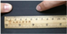 | Melting rate: ☆ Tensile strength: ○ Flexibility: □ |
| 2 | 10 | 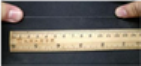 | Melting rate: ☆☆ Tensile strength: ○○ Flexibility: □□ |
| 3 | 15 | 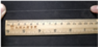 | Melting rate: ☆☆☆ Tensile strength: ○○○ Flexibility: □□□ |
| 4 | 20 | 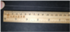 | Melting rate: ☆☆☆ Tensile strength: ○ Flexibility: □□ |
| No. | Temperature | Samples Exhibition | Characteristics and Analysis |
|---|---|---|---|
| 1 | 160 °C | 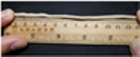 | Melting rate: ☆ Flowability: △ Forming silk: ◇ |
| 2 | 180 °C |  | Melting rate: ☆ Flowability: △ Forming silk: ◇ |
| 3 | 200 °C | 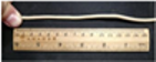 | Melting rate: ☆☆ Flowability: △△ Forming silk: ◇◇ |
| 4 | 220 °C | 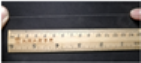 | Melting rate: ☆☆☆ Flowability: △△△ Forming silk: ◇◇◇ |
Publisher’s Note: MDPI stays neutral with regard to jurisdictional claims in published maps and institutional affiliations. |
© 2022 by the authors. Licensee MDPI, Basel, Switzerland. This article is an open access article distributed under the terms and conditions of the Creative Commons Attribution (CC BY) license (https://creativecommons.org/licenses/by/4.0/).
Share and Cite
Liu, H.; Tian, J.; Pan, G.; Xie, Y.; Yao, Q. Preparation of the Flexible Green Body of YAG Ceramic Fiber by Melt Spinning. Polymers 2022, 14, 2096. https://doi.org/10.3390/polym14102096
Liu H, Tian J, Pan G, Xie Y, Yao Q. Preparation of the Flexible Green Body of YAG Ceramic Fiber by Melt Spinning. Polymers. 2022; 14(10):2096. https://doi.org/10.3390/polym14102096
Chicago/Turabian StyleLiu, Hongmei, Junjie Tian, Gangwei Pan, Yongjin Xie, and Qing Yao. 2022. "Preparation of the Flexible Green Body of YAG Ceramic Fiber by Melt Spinning" Polymers 14, no. 10: 2096. https://doi.org/10.3390/polym14102096
APA StyleLiu, H., Tian, J., Pan, G., Xie, Y., & Yao, Q. (2022). Preparation of the Flexible Green Body of YAG Ceramic Fiber by Melt Spinning. Polymers, 14(10), 2096. https://doi.org/10.3390/polym14102096