
Strength Profile Pattern of FRP-Reinforced Concrete Structures: A Performance Analysis through Finite Element Analysis and Empirical Modeling Technique


Abstract

1. Introduction
Scope and Significance
2. Materials and Methods
Database for Empirical Modeling
3. Evaluation of Previous Models
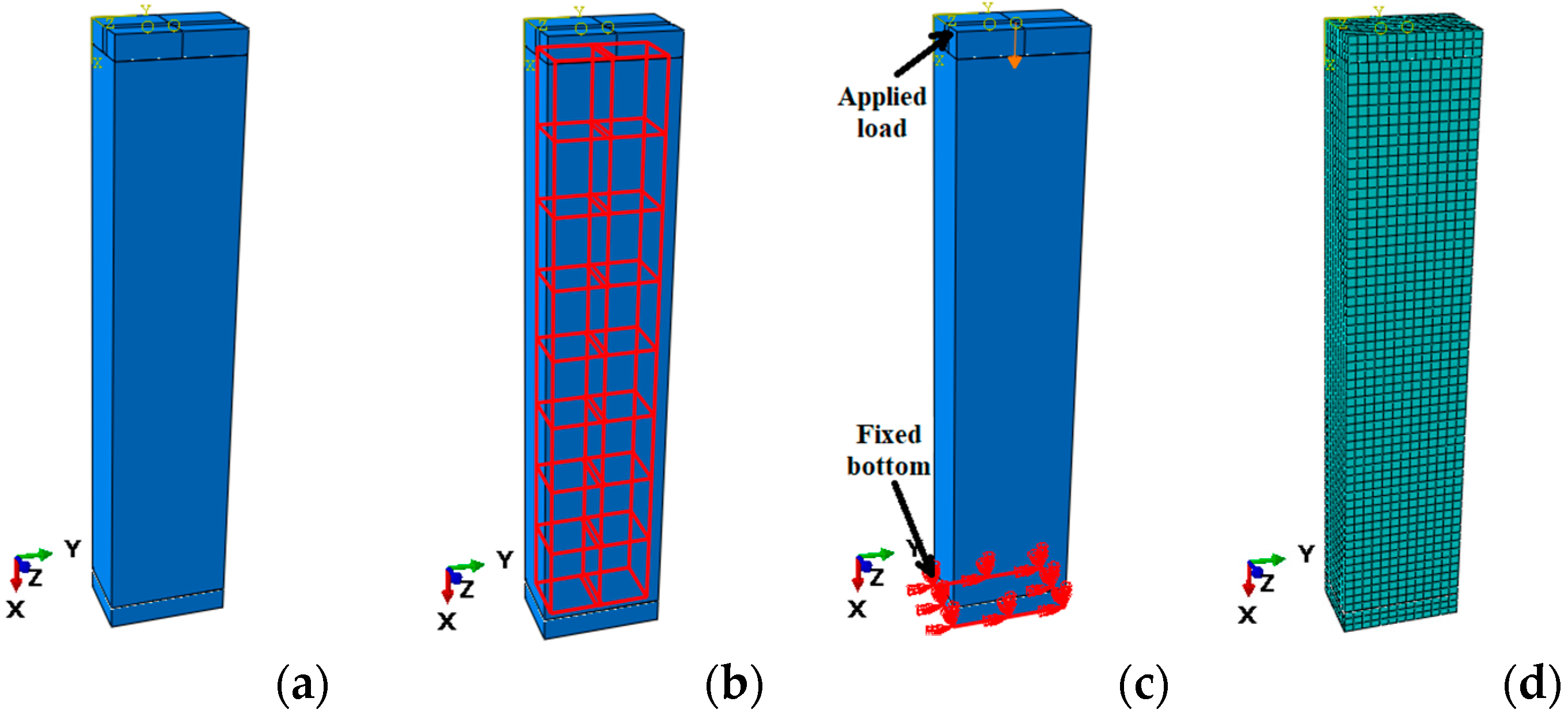
4. Finite Element Modelling
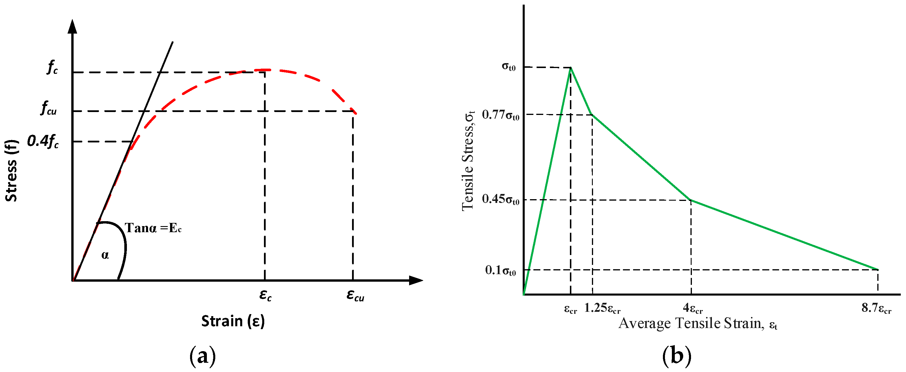
4.1. Simulation of Concrete Material
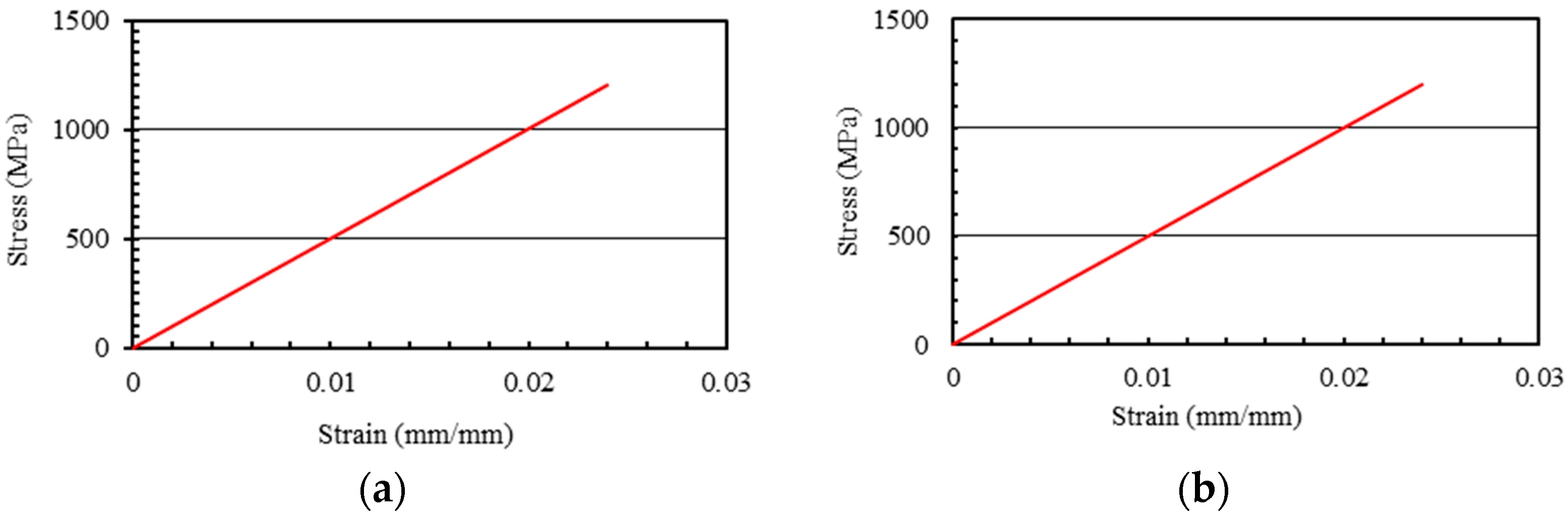
4.2. Simulations of FRP Bars
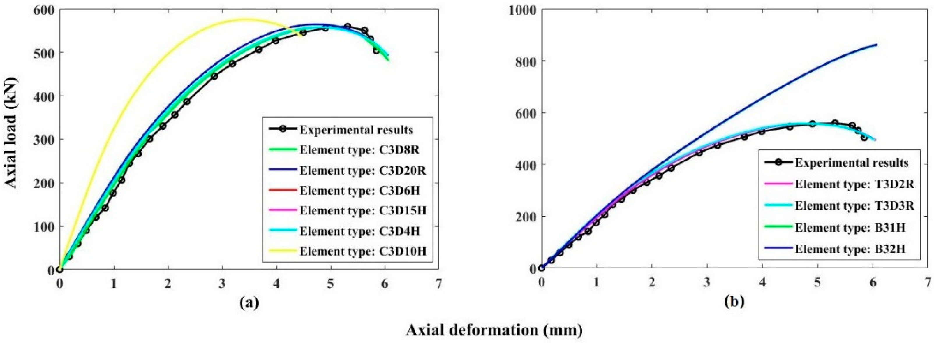
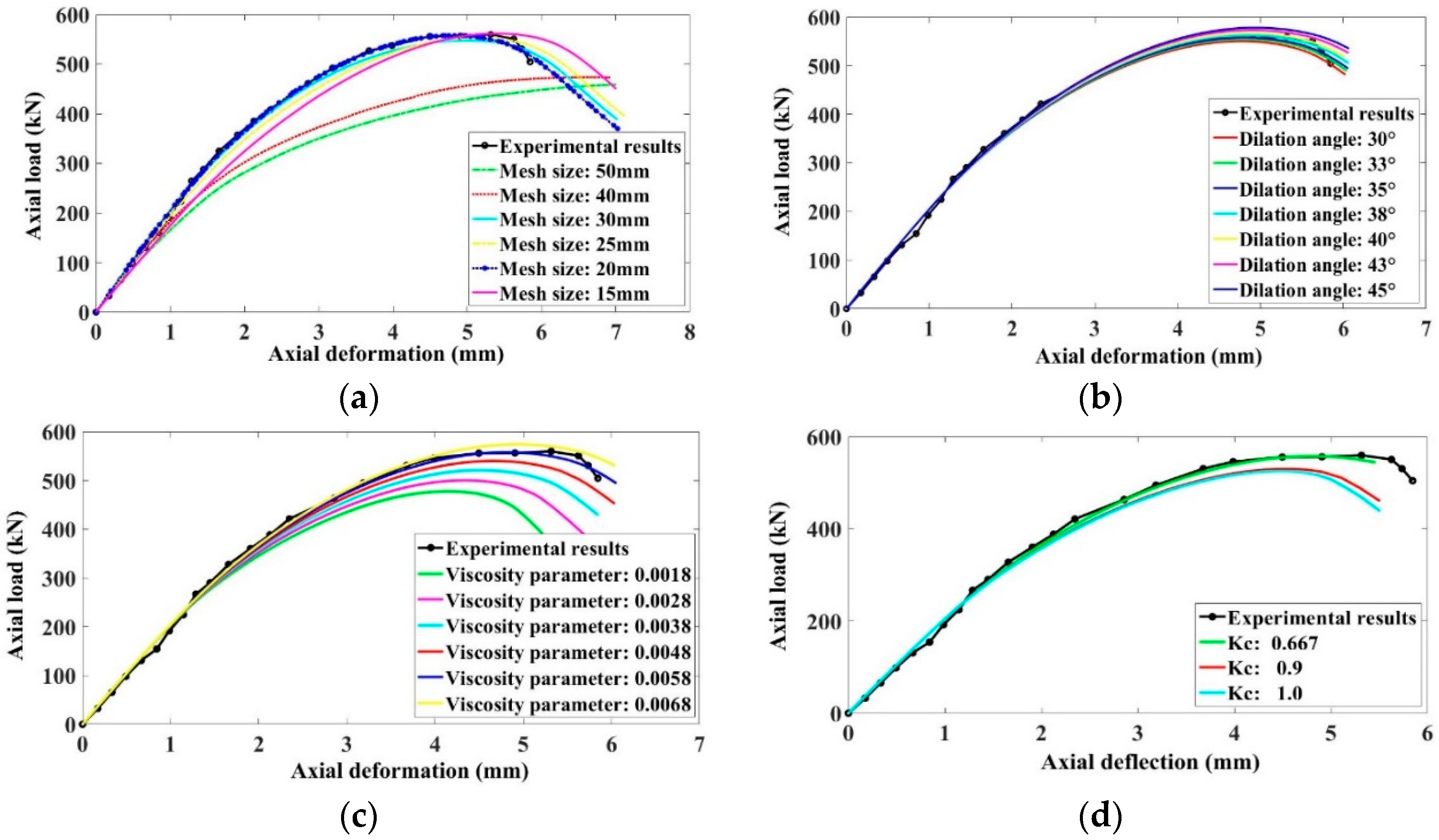
4.3. Calibration of FEM
5. Results and Discussion
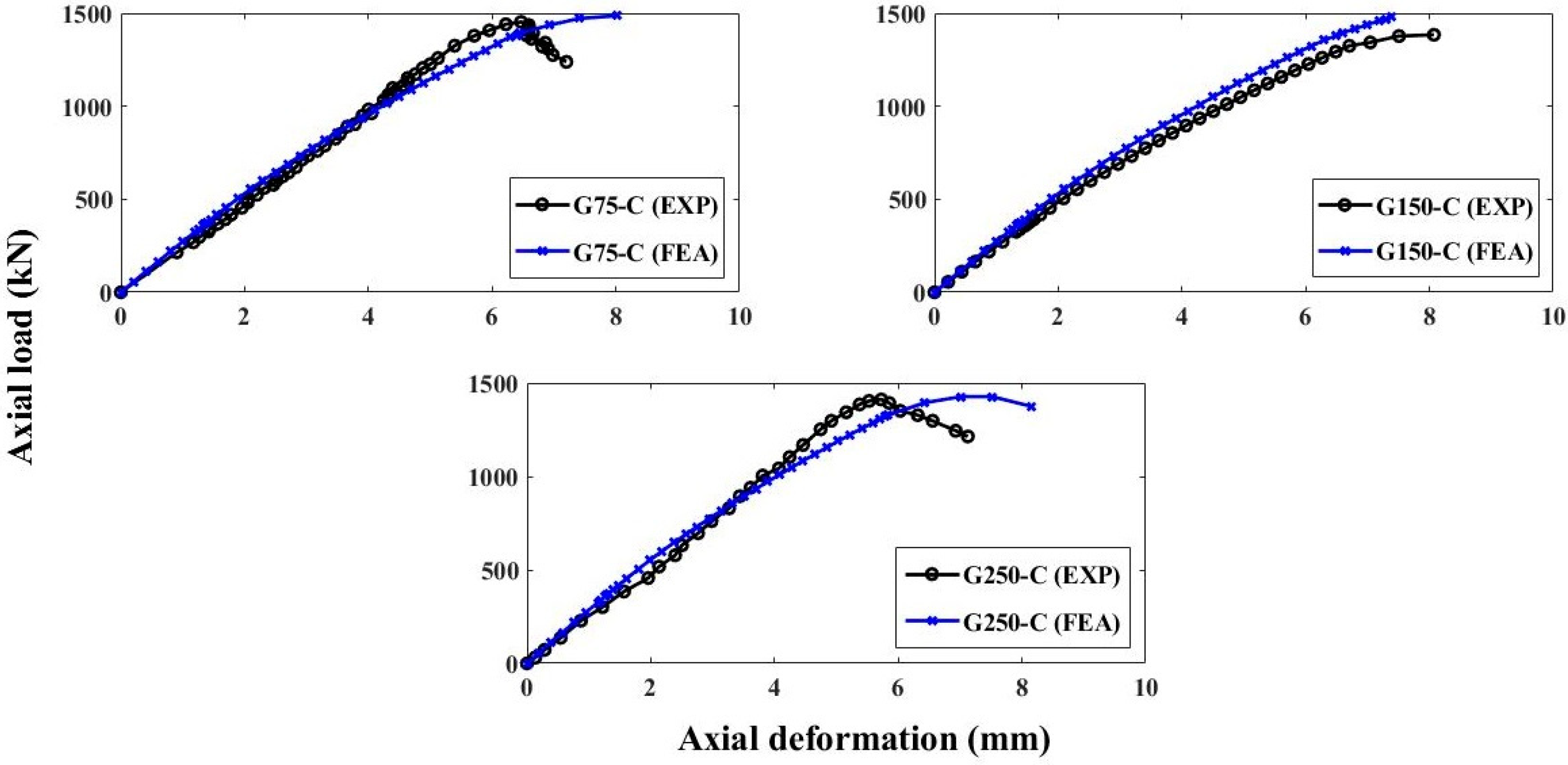
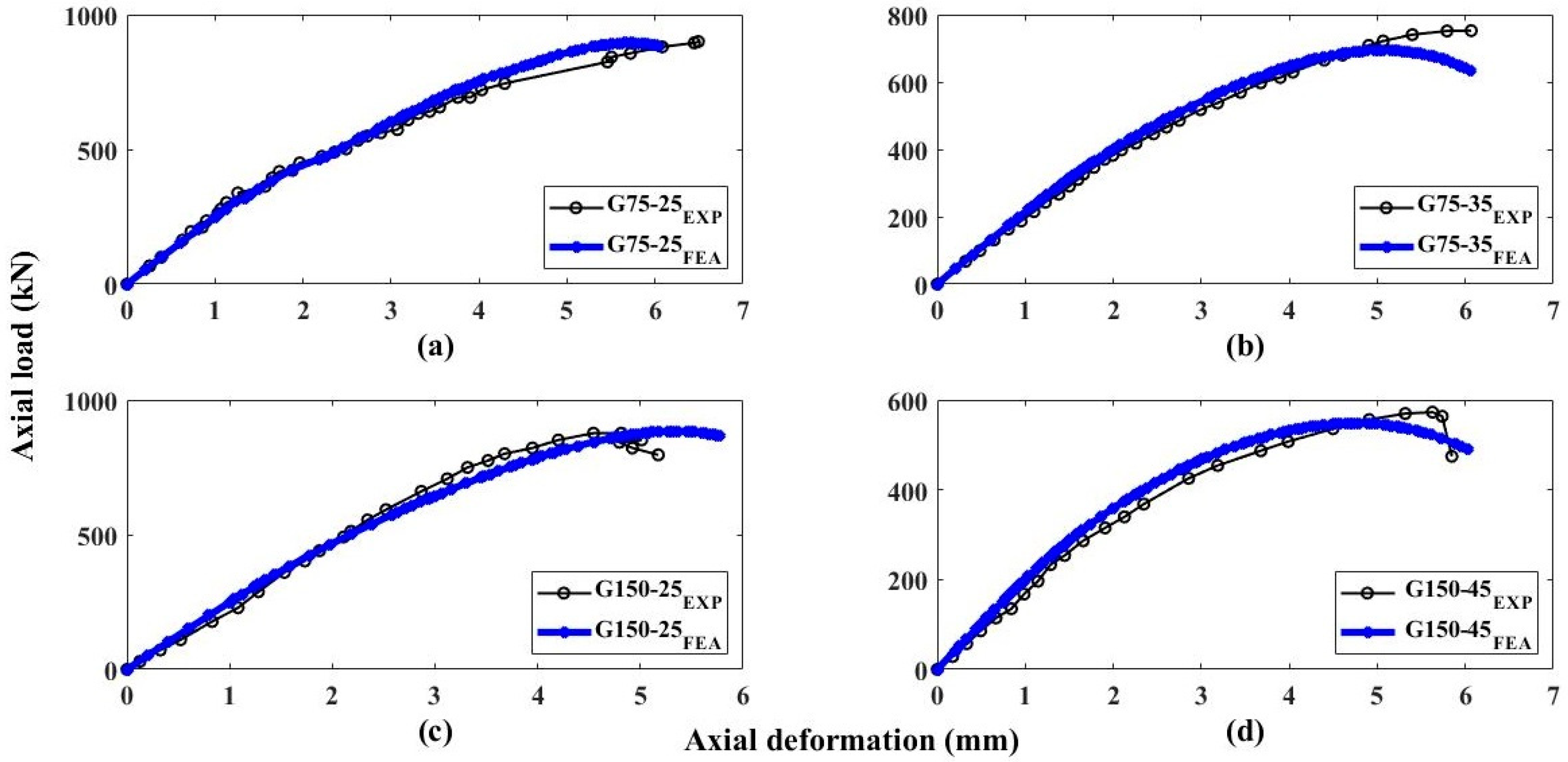
Load-Deflection Performance of FEM
6. Parametric Investigation
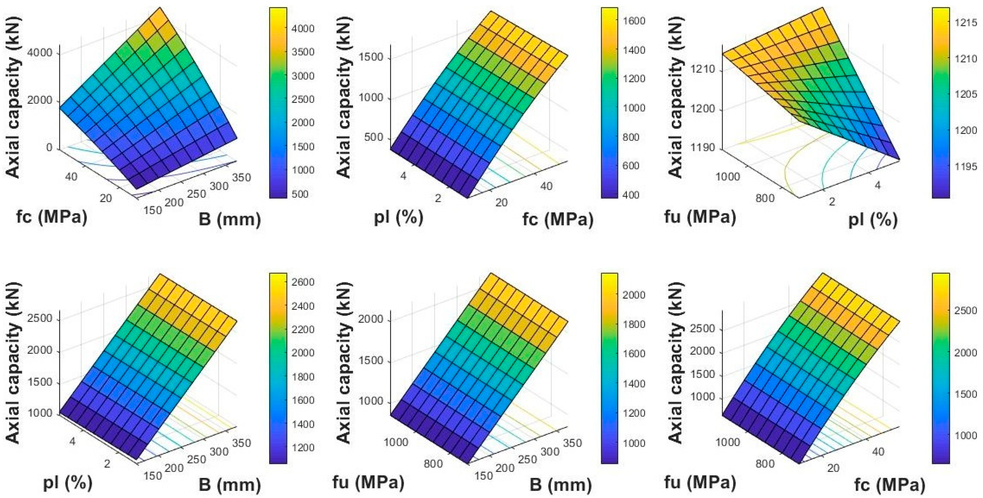
6.1. Using FEA Model
6.1.1. Influence of Width of Column (B)
6.1.2. Influence of Concrete Compressive Strength ()
6.1.3. Influence of Longitudinal Reinforcement Ratio ()
6.1.4. Influence of Tensile Strength of FRP Rebars ()
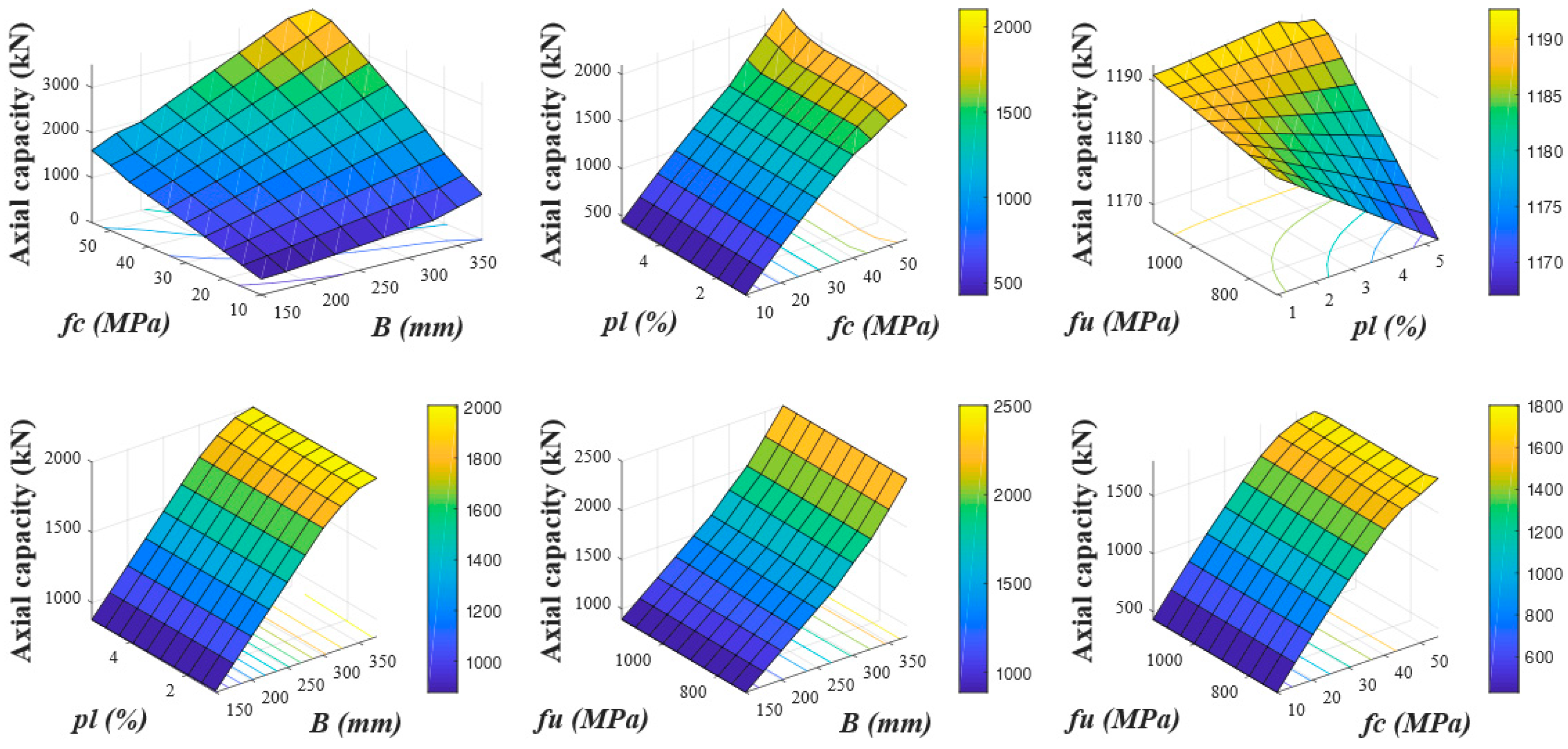
6.2. Using Empirical Model
6.2.1. Influence of Width of Column (B)
6.2.2. Influence of Concrete Compressive Strength ()
6.2.3. Influence of Longitudinal Reinforcement Ratio ()
6.2.4. Influence of Tensile Strength of FRP Rebars (fu)
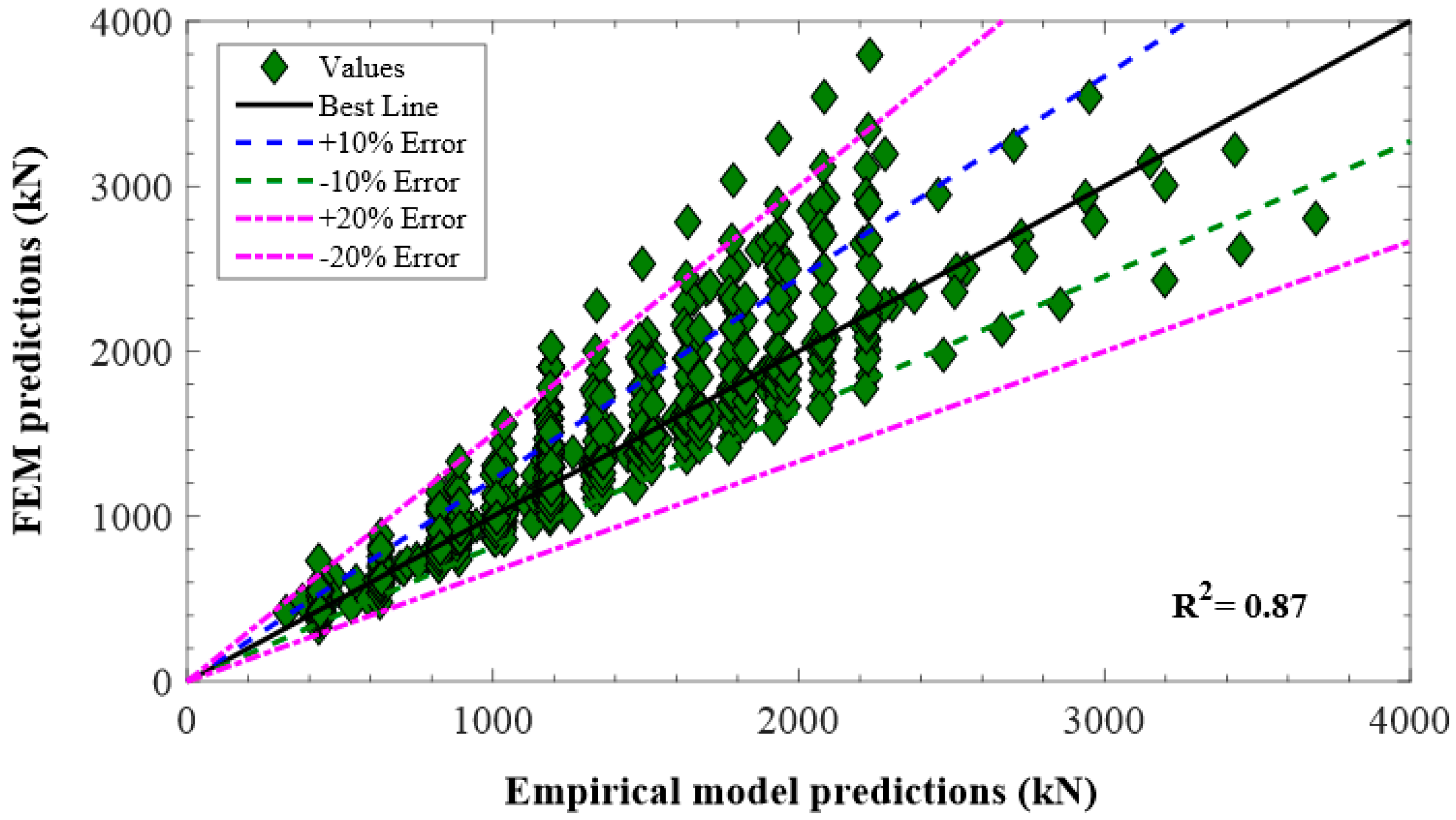
7. Validation and Comparison of Proposed Models
8. Conclusions
Author Contributions
Funding
Data Availability Statement
Conflicts of Interest
Appendix A

| Sr. No. | Research Study | Longitudinal Reinforcement | Transverse Reinforcement | Axial Strength | |||||||||
|---|---|---|---|---|---|---|---|---|---|---|---|---|---|
| (mm) | (mm) | (mm) | (MPa) | (MPa) | (GPa) | (%) | Bars | (%) | Type | (%) | (kN) | ||
| 1 | Afifi et al. [23] | - | - | 300 | 20 | 934 | 55.4 | 1.56 | 8 No. 5 | 2.2 | GS | 1 | 2920 |
| 2 | Afifi et al. [23] | - | - | 300 | 20 | 934 | 55.4 | 1.56 | 4 No. 5 | 1.1 | GS | 1 | 2826 |
| 3 | Afifi et al. [23] | - | - | 300 | 20 | 934 | 55.4 | 1.56 | 12 No. 5 | 3.2 | GS | 1 | 2998 |
| 4 | Afifi et al. [23] | - | - | 300 | 20 | 934 | 55.4 | 1.56 | 8 No. 5 | 2.2 | GS | 0.45 | 2857 |
| 5 | Afifi et al. [23] | - | - | 300 | 20 | 934 | 55.4 | 1.56 | 8 No. 5 | 2.2 | GS | 1.87 | 3019 |
| 6 | Afifi et al. [23] | - | - | 300 | 20 | 934 | 55.4 | 1.56 | 8 No. 5 | 2.2 | GS | 2.07 | 2964 |
| 7 | Afifi et al. [23] | - | - | 300 | 20 | 934 | 55.4 | 1.56 | 8 No. 5 | 2.2 | GS | 0.69 | 2804 |
| 8 | Afifi et al. [23] | - | - | 300 | 20 | 934 | 55.4 | 1.56 | 8 No. 5 | 2.2 | GS | 1.03 | 2951 |
| 9 | Afifi et al. [23] | - | - | 300 | 20 | 934 | 55.4 | 1.56 | 8 No. 5 | 2.2 | GS | 1.03 | 2865 |
| 10 | Afifi et al. [33] | - | - | 301 | 21 | 934 | 55.4 | 1.56 | 8 No. 5 | 2.2 | GS | 1.5 | 2840 |
| 11 | Afifi et al. [33] | - | - | 302 | 22 | 934 | 55.4 | 1.56 | 8 No. 5 | 2.2 | GS | 1.5 | 2871 |
| 12 | Afifi et al. [33] | - | - | 303 | 23 | 934 | 55.4 | 1.56 | 8 No. 5 | 2.2 | GS | 1.5 | 2935 |
| 13 | AlAjarmeh et al. [67] | - | - | 250 | 31.8 | 1237 | 60 | 2.1 | 6 No. 5 | 2.41 | GS | 1.49 | 1588 |
| 14 | AlAjarmeh et al. [67] | - | - | 250 | 31.8 | 1237 | 60 | 2.1 | 6 No. 5 | 2.47 | GS | 1.56 | 1408 |
| 15 | AlAjarmeh et al. [67] | - | - | 250 | 31.8 | 1237 | 60 | 2.1 | 6 No. 5 | 2.59 | GS | 1.69 | 1559 |
| 16 | AlAjarmeh et al. [67] | - | - | 250 | 31.8 | 1237 | 60 | 2.1 | 6 No. 5 | 2.78 | GS | 1.92 | 1411 |
| 17 | AlAjarmeh et al. [68] | - | - | 251 | 25 | 1281.5 | 61.3 | 2.1 | 6 No. 4 | 1.78 | GS | 1.57 | 1035.3 |
| 18 | AlAjarmeh et al. [68] | - | - | 252 | 25 | 1237.4 | 60.5 | 2.1 | 6 No. 5 | 2.79 | GS | 1.57 | 1109.2 |
| 19 | AlAjarmeh et al. [68] | - | - | 253 | 25 | 1270 | 60.5 | 2.1 | 6 No. 6 | 4 | GS | 1.57 | 1247.9 |
| 20 | AlAjarmeh et al. [68] | - | - | 254 | 25 | 1237.4 | 60.5 | 2.1 | 4 No. 5 | 1.86 | GS | 1.57 | 983.3 |
| 21 | AlAjarmeh et al. [68] | - | - | 255 | 25 | 1237.4 | 60.5 | 2.1 | 8 No. 5 | 3.72 | GS | 1.57 | 1406.1 |
| 22 | AlAjarmeh et al. [68] | - | - | 256 | 25 | 1281.5 | 61.3 | 2.1 | 9 No. 4 | 2.67 | GS | 1.57 | 1204.2 |
| 23 | Alsayed et al. [69] | 250 | 450 | - | 39 | 800 | 40 | 1.5 | 6 No. 5 | 1 | SH | 0.15 | 3285 |
| 24 | Alsayed et al. [69] | 250 | 450 | - | 39 | 800 | 40 | 1.5 | 6 No. 5 | 1 | SH | 0.15 | 3285 |
| 25 | Alsayed et al. [69] | 250 | 450 | - | 39 | 800 | 40 | 1.5 | 6 No. 5 | 1 | SH | 0.15 | 3285 |
| 26 | Alsayed et al. [69] | 250 | 450 | - | 38.5 | 800 | 40 | 1.5 | 6 No. 5 | 1 | GH | 0.18 | 3301 |
| 27 | Alsayed et al. [69] | 250 | 450 | - | 38.5 | 800 | 40 | 1.5 | 6 No. 5 | 1 | GH | 0.18 | 3301 |
| 28 | Alsayed et al. [69] | 250 | 450 | - | 38.5 | 800 | 40 | 1.5 | 6 No. 5 | 1 | GH | 0.18 | 3301 |
| 29 | De Luca et al. [70] | 610 | 610 | - | 43.7 | 608 | 44.2 | 1.38 | 8 No. 8 | 1 | GH | 0.63 | 15235 |
| 30 | De Luca et al. [70] | 610 | 610 | - | 40.6 | 712 | 44.4 | 1.6 | 8 No 8 | 1 | GH | 0.63 | 12949 |
| 31 | De Luca et al. [70] | 610 | 610 | - | 36.1 | 608 | 44.2 | 1.38 | 8 No. 8 | 1 | GH | 2.5 | 11926 |
| 32 | De Luca et al. [70] | 610 | 610 | - | 32.8 | 712 | 44.4 | 1.6 | 8 No 8 | 1 | GH | 2.5 | 10751 |
| 33 | Dong et al. [15] | - | - | 215 | 40 | 930 | 59 | 1.6 | 3 No. 3 | 0.55 | GS | 0.94 | 1018 |
| 34 | Dong et al. [15] | - | - | 215 | 40 | 930 | 59 | 1.6 | 4 No. 3 | 0.73 | GS | 0.94 | 1179 |
| 35 | Dong et al. [15] | - | - | 215 | 40 | 930 | 59 | 1.6 | 5 No. 3 | 0.92 | GS | 0.94 | 1288 |
| 36 | Dong et al. [15] | - | - | 215 | 40 | 930 | 59 | 1.6 | 6 No. 3 | 1.1 | GS | 0.94 | 1381 |
| 37 | Dong et al. [15] | - | - | 215 | 40 | 930 | 59 | 1.6 | 4 No. 3 | 0.73 | GS | 2.75 | 1459 |
| 38 | Dong et al. [15] | - | - | 215 | 40 | 930 | 59 | 1.6 | 4 No. 3 | 0.73 | GS | 2.75 | 1037 |
| 39 | Dong et al. [15] | - | - | 215 | 40 | 880 | 59 | 1.6 | 4 No. 3 | 0.73 | GS | 2.75 | 523 |
| 40 | Dong et al. [15] | - | - | 215 | 37 | 880 | 59 | 1.6 | 4 No. 3 | 0.73 | GS | 2.75 | 318 |
| 41 | Dong et al. [15] | - | - | 215 | 37 | 880 | 59 | 1.6 | 5 No. 3 | 0.73 | GS | 1.39 | 1290 |
| 42 | Dong et al. [15] | - | - | 215 | 37 | 880 | 59 | 1.6 | 6 No. 3 | 0.73 | GS | 1.39 | 944 |
| 43 | Dong et al. [15] | - | - | 215 | 37 | 880 | 59 | 1.6 | 7 No. 3 | 0.73 | GS | 1.39 | 527 |
| 44 | Dong et al. [15] | - | - | 215 | 37 | 880 | 59 | 1.6 | 8 No. 3 | 0.73 | GS | 1.39 | 296 |
| 45 | Elchalakani and Ma [26] | 160 | 260 | - | 32.8 | 1200 | 50 | 2.4 | 6 No. 4 | 1.8 | GH | 0.5 | 1367 |
| 46 | Elchalakani and Ma [26] | 160 | 260 | - | 32.8 | 1200 | 50 | 2.4 | 6 No. 4 | 1.8 | GH | 0.5 | 880 |
| 47 | Elchalakani and Ma [26] | 160 | 260 | - | 32.8 | 1200 | 50 | 2.4 | 6 No. 4 | 1.8 | GH | 0.5 | 584 |
| 48 | Elchalakani and Ma [26] | 160 | 260 | - | 32.8 | 1200 | 50 | 2.4 | 6 No. 4 | 1.8 | GH | 1 | 1449 |
| 49 | Elchalakani and Ma [26] | 160 | 260 | - | 32.8 | 1200 | 50 | 2.4 | 6 No. 4 | 1.8 | GH | 1 | 917 |
| 50 | Elchalakani and Ma [26] | 160 | 260 | - | 32.8 | 1200 | 50 | 2.4 | 6 No. 4 | 1.8 | GH | 1 | 788 |
| 51 | Elchalakani and Ma [26] | 160 | 260 | - | 32.8 | 1200 | 50 | 2.4 | 6 No. 4 | 1.8 | GH | 0.3 | 1402 |
| 52 | Elchalakani et al. [29] | 160 | 260 | - | 32.8 | 930 | 59 | 1.7 | 6 No. 4 | 1.8 | GH | 0.3 | 1402 |
| 53 | Elchalakani et al. [29] | 160 | 260 | - | 32.8 | 930 | 59 | 1.7 | 6 No. 4 | 1.8 | GH | 0.5 | 1367 |
| 54 | Elchalakani et al. [29] | 160 | 260 | - | 32.8 | 930 | 59 | 1.7 | 6 No. 4 | 1.8 | GH | 1 | 1449 |
| 55 | Elchalakani et al. [29] | 160 | 260 | - | 32.8 | 930 | 59 | 1.7 | 6 No. 4 | 1.8 | GH | 0.5 | 880 |
| 56 | Elchalakani et al. [29] | 160 | 260 | - | 32.8 | 930 | 59 | 1.7 | 6 No. 4 | 1.8 | GH | 1 | 917 |
| 57 | Elchalakani et al. [29] | 160 | 260 | - | 32.8 | 930 | 59 | 1.7 | 6 No. 4 | 1.8 | GH | 1 | 788 |
| 58 | Elchalakani et al. [29] | 160 | 260 | - | 32.8 | 930 | 59 | 1.7 | 6 No. 4 | 1.8 | GH | 0.5 | 584 |
| 59 | Elchalakani et al. [29] | 160 | 260 | - | 32.8 | 930 | 59 | 1.7 | 6 No. 4 | 1.8 | GH | 0.3 | 1041 |
| 60 | Elchalakani et al. [29] | 160 | 260 | - | 32.8 | 930 | 59 | 1.7 | 6 No. 4 | 1.8 | GH | 0.5 | 1194 |
| 61 | Elchalakani et al. [29] | 160 | 260 | - | 32.8 | 930 | 59 | 1.7 | 6 No. 4 | 1.8 | GH | 1 | 1357 |
| 62 | Elchalakani et al. [29] | 160 | 260 | - | 32.8 | 930 | 59 | 1.7 | 6 No. 4 | 1.8 | GH | 0.5 | 657 |
| 63 | Elchalakani et al. [29] | 160 | 260 | - | 32.8 | 930 | 59 | 1.7 | 6 No. 4 | 1.8 | GH | 1 | 804 |
| 64 | Elchalakani et al. [29] | 160 | 160 | - | 32.8 | 930 | 59 | 1.7 | 6 No. 4 | 1.8 | GH | 0.5 | 353 |
| 65 | Elchalakani et al. [29] | 160 | 160 | - | 32.8 | 930 | 59 | 1.7 | 6 No. 4 | 1.8 | GH | 1 | 454 |
| 66 | Elchalakani et al. [29] | 160 | 160 | - | 32.8 | 930 | 59 | 1.7 | 6 No. 4 | 1.8 | GH | 0.5 | 234 |
| 67 | Elchalakani et al. [29] | 160 | 160 | - | 32.8 | 930 | 59 | 1.7 | 6 No. 4 | 1.8 | GH | 1 | 244 |
| 68 | Guerin et al. [71] | 405 | 405 | - | 25.3 | 600 | 40 | 1.5 | 6 No. 6 | 1 | GH | 0.66 | 4587 |
| 69 | Guerin et al. [71] | 405 | 405 | - | 25.3 | 600 | 40 | 1.5 | 6 No. 6 | 1 | GH | 0.66 | 3433 |
| 70 | Guerin et al. [71] | 405 | 405 | - | 25.3 | 600 | 40 | 1.5 | 6 No. 6 | 1 | GH | 0.66 | 1591 |
| 71 | Guerin et al. [71] | 405 | 405 | - | 25.3 | 600 | 40 | 1.5 | 6 No. 6 | 1 | GH | 0.66 | 645 |
| 72 | Guerin et al. [71] | 405 | 405 | - | 25.3 | 600 | 40 | 1.5 | 6 No. 6 | 1 | GH | 0.66 | 4616 |
| 73 | Guerin et al. [71] | 405 | 405 | - | 25.3 | 600 | 40 | 1.5 | 6 No. 6 | 1 | GH | 0.66 | 3405 |
| 74 | Guerin et al. [71] | 405 | 405 | - | 25.3 | 600 | 40 | 1.5 | 6 No. 6 | 1 | GH | 0.66 | 1576 |
| 75 | Guerin et al. [71] | 405 | 405 | - | 25.3 | 600 | 40 | 1.5 | 6 No. 6 | 1 | GH | 0.66 | 636 |
| 76 | Guerin et al. [72] | 405 | 405 | - | 25.3 | 600 | 40 | 1.5 | 8 No. 6 | 1.4 | GH | 0.84 | 5028 |
| 77 | Guerin et al. [72] | 405 | 405 | - | 25.3 | 600 | 40 | 1.5 | 8 No. 6 | 1.4 | GH | 0.84 | 3627 |
| 78 | Guerin et al. [72] | 405 | 405 | - | 25.3 | 600 | 40 | 1.5 | 8 No. 6 | 1.4 | GH | 0.84 | 2035 |
| 79 | Guerin et al. [72] | 405 | 405 | - | 25.3 | 600 | 40 | 1.5 | 8 No. 6 | 1.4 | GH | 0.84 | 914 |
| 80 | Guerin et al. [72] | 405 | 405 | - | 25.3 | 600 | 40 | 1.5 | 8 No. 8 | 2.5 | GH | 0.63 | 5294 |
| 81 | Guerin et al. [72] | 405 | 405 | - | 25.3 | 600 | 40 | 1.5 | 8 No. 8 | 2.5 | GH | 0.63 | 3790 |
| 82 | Guerin et al. [72] | 405 | 405 | - | 25.3 | 600 | 40 | 1.5 | 8 No. 8 | 2.5 | GH | 0.63 | 2110 |
| 83 | Guerin et al. [72] | 405 | 405 | - | 25.3 | 600 | 40 | 1.5 | 8 No. 8 | 2.5 | GH | 0.63 | 1008 |
| 84 | Hadhood et al. [52] | - | - | 305 | 35 | 1680 | 141 | 1.19 | 8 No. 5 | 2.2 | GH | 2.68 | 2564 |
| 85 | Hadhood et al. [52] | - | - | 305 | 35 | 1680 | 141 | 1.19 | 8 No. 5 | 2.2 | GH | 2.68 | 2060 |
| 86 | Hadhood et al. [52] | - | - | 305 | 35 | 1680 | 141 | 1.19 | 8 No. 5 | 2.2 | GH | 2.68 | 1511 |
| 87 | Hadhood et al. [52] | - | - | 305 | 35 | 1680 | 141 | 1.19 | 8 No. 5 | 2.2 | GH | 2.68 | 776 |
| 88 | Hadhood et al. [52] | - | - | 305 | 35 | 1680 | 141 | 1.19 | 8 No. 5 | 2.2 | GH | 2.68 | 366 |
| 89 | Hadhood et al. [52] | - | - | 305 | 35 | 1680 | 141 | 1.19 | 8 No. 5 | 2.2 | GS | 1 | 2608 |
| 90 | Hadhood et al. [52] | - | - | 305 | 35 | 1680 | 141 | 1.19 | 8 No. 5 | 2.2 | GS | 1 | 2134 |
| 91 | Hadhood et al. [52] | - | - | 305 | 35 | 1680 | 141 | 1.19 | 8 No. 5 | 2.2 | GS | 1 | 1513 |
| 92 | Hadhood et al. [52] | - | - | 305 | 35 | 1680 | 141 | 1.19 | 8 No. 5 | 2.2 | GS | 1 | 745 |
| 93 | Hadhood et al. [52] | - | - | 305 | 35 | 1680 | 141 | 1.19 | 8 No. 5 | 2.2 | GS | 1 | 654 |
| 94 | Hadhood et al. [52] | - | - | 305 | 35 | 1680 | 141 | 1.19 | 12 No. 5 | 3.3 | GS | 1 | 2670 |
| 95 | Hadhood et al. [52] | - | - | 305 | 35 | 1680 | 141 | 1.19 | 12 No. 5 | 3.3 | GS | 1 | 2123 |
| 96 | Hadhood et al. [52] | - | - | 305 | 35 | 1680 | 141 | 1.19 | 12 No. 5 | 3.3 | GS | 1 | 1527 |
| 97 | Hadhood et al. [52] | - | - | 305 | 35 | 1680 | 141 | 1.19 | 12 No. 5 | 3.3 | GS | 1 | 852 |
| 98 | Hadhood et al. [52] | - | - | 305 | 35 | 1680 | 141 | 1.19 | 12 No. 5 | 3.3 | GS | 1 | 378 |
| 99 | Hadhood et al. [73] | - | - | 305 | 35 | 1680 | 141 | 1.19 | 8 No. 5 | 2.2 | GS | 1.8 | 2652 |
| 100 | Hadhood et al. [73] | - | - | 305 | 35 | 1680 | 141 | 1.19 | 8 No. 5 | 2.2 | GS | 1.8 | 2086 |
| 101 | Hadhood et al. [73] | - | - | 305 | 35 | 1680 | 141 | 1.19 | 8 No. 5 | 2.2 | GS | 1.8 | 1483 |
| 102 | Hadhood et al. [73] | - | - | 305 | 35 | 1680 | 141 | 1.19 | 8 No. 5 | 2.2 | GS | 1.8 | 747 |
| 103 | Hadhood et al. [73] | - | - | 305 | 35 | 1680 | 141 | 1.19 | 8 No. 5 | 2.2 | GS | 1.8 | 655 |
| 104 | Hadhood et al. [73] | - | - | 305 | 70.2 | 1289 | 54.9 | 2.3 | 8 No. 5 | 2.2 | GS | 1.1 | 4709 |
| 105 | Hadhood et al. [73] | - | - | 305 | 70.2 | 1289 | 54.9 | 2.3 | 8 No. 5 | 2.2 | GS | 1.1 | 3309 |
| 106 | Hadhood et al. [73] | - | - | 305 | 70.2 | 1289 | 54.9 | 2.3 | 8 No. 5 | 2.2 | GS | 1.1 | 2380 |
| 107 | Hadhood et al. [73] | - | - | 305 | 70.2 | 1289 | 54.9 | 2.3 | 8 No. 5 | 2.2 | GS | 1.1 | 1112 |
| 108 | Hadhood et al. [73] | - | - | 305 | 70.2 | 1289 | 54.9 | 2.3 | 8 No. 5 | 2.2 | GS | 1.1 | 797 |
| 109 | Hadhood et al. [73] | - | - | 305 | 70.2 | 1289 | 54.9 | 2.3 | 8 No. 5 | 2.2 | GH | 1.1 | 4689 |
| 110 | Hadhood et al. [73] | - | - | 305 | 70.2 | 1289 | 54.9 | 2.3 | 8 No. 5 | 2.2 | GH | 1.1 | 3299 |
| 111 | Hadhood et al. [73] | - | - | 305 | 70.2 | 1289 | 54.9 | 2.3 | 8 No. 5 | 2.2 | GH | 1.1 | 2435 |
| 112 | Hadhood et al. [73] | - | - | 305 | 70.2 | 1289 | 54.9 | 2.3 | 8 No. 5 | 2.2 | GH | 1.1 | 1054 |
| 113 | Hadhood et al. [73] | - | - | 305 | 70.2 | 1289 | 54.9 | 2.3 | 8 No. 5 | 2.2 | GH | 1.1 | 838 |
| 114 | Hadhood et al. [73] | - | - | 305 | 70.2 | 1289 | 54.9 | 2.3 | 12 No. 5 | 3.2 | GS | 1.1 | 4716 |
| 115 | Hadhood et al. [73] | - | - | 305 | 70.2 | 1289 | 54.9 | 2.3 | 12 No. 5 | 3.2 | GS | 1.1 | 3380 |
| 116 | Hadhood et al. [73] | - | - | 305 | 70.2 | 1289 | 54.9 | 2.3 | 12 No. 5 | 3.2 | GS | 1.1 | 2339 |
| 117 | Hadhood et al. [73] | - | - | 305 | 70.2 | 1289 | 54.9 | 2.3 | 12 No. 5 | 3.2 | GS | 1.1 | 1135 |
| 118 | Hadhood et al. [73] | - | - | 305 | 70.2 | 1289 | 54.9 | 2.3 | 12 No. 5 | 3.2 | GS | 1.1 | 713 |
| 119 | Hadhood et al. [73] | - | - | 305 | 70.2 | 1289 | 54.9 | 2.3 | 8 No. 5 | 2.2 | GS | 1.1 | 5120 |
| 120 | Hadhood et al. [73] | - | - | 305 | 70.2 | 1289 | 54.9 | 2.3 | 8 No. 5 | 2.2 | GS | 1.1 | 3671 |
| 121 | Hadhood et al. [73] | - | - | 305 | 70.2 | 1289 | 54.9 | 2.3 | 8 No. 5 | 2.2 | GS | 1.1 | 2538 |
| 122 | Hadhood et al. [73] | - | - | 305 | 70.2 | 1289 | 54.9 | 2.3 | 8 No. 5 | 2.2 | GS | 1.1 | 1392 |
| 123 | Hadhood et al. [73] | - | - | 305 | 70.2 | 1289 | 54.9 | 2.3 | 8 No. 5 | 2.2 | GS | 1.1 | 611 |
| 124 | Hadhood et al. [73] | - | - | 305 | 70.2 | 1289 | 54.9 | 2.3 | 8 No. 5 | 2.2 | GS | 1.7 | 4680 |
| 125 | Hadhood et al. [73] | - | - | 305 | 70.2 | 1289 | 54.9 | 2.3 | 8 No. 5 | 2.2 | GS | 1.7 | 3341 |
| 126 | Hadhood et al. [73] | - | - | 305 | 70.2 | 1289 | 54.9 | 2.3 | 8 No. 5 | 2.2 | GS | 1.7 | 2460 |
| 127 | Hadhood et al. [73] | - | - | 305 | 70.2 | 1289 | 54.9 | 2.3 | 8 No. 5 | 2.2 | GS | 1.7 | 1061 |
| 128 | Hadhood et al. [73] | - | - | 305 | 70.2 | 1289 | 54.9 | 2.3 | 8 No. 5 | 2.2 | GS | 1.7 | 682 |
| 129 | Hadhood et al. [73] | - | - | 305 | 35 | 1289 | 54.9 | 2.3 | 8 No. 5 | 2.2 | GS | 1.1 | 2608 |
| 130 | Hadhood et al. [73] | - | - | 305 | 35 | 1289 | 54.9 | 2.3 | 8 No. 5 | 2.2 | GS | 1.1 | 2134 |
| 131 | Hadhood et al. [73] | - | - | 305 | 35 | 1289 | 54.9 | 2.3 | 8 No. 5 | 2.2 | GS | 1.1 | 1512 |
| 132 | Hadhood et al. [73] | - | - | 305 | 35 | 1289 | 54.9 | 2.3 | 8 No. 5 | 2.2 | GS | 1.1 | 745 |
| 133 | Hadhood et al. [73] | - | - | 305 | 35 | 1289 | 54.9 | 2.3 | 8 No. 5 | 2.2 | GS | 1.1 | 354 |
| 134 | Hadhood et al. [73] | - | - | 305 | 35 | 1289 | 54.9 | 2.3 | 8 No. 5 | 2.2 | GS | 1.1 | 3090 |
| 135 | Hadhood et al. [73] | - | - | 305 | 35 | 1289 | 54.9 | 2.3 | 8 No. 5 | 2.2 | GS | 1.1 | 2342 |
| 136 | Hadhood et al. [73] | - | - | 305 | 35 | 1289 | 54.9 | 2.3 | 8 No. 5 | 2.2 | GS | 1.1 | 1746 |
| 137 | Hadhood et al. [73] | - | - | 305 | 35 | 1289 | 54.9 | 2.3 | 8 No. 5 | 2.2 | GS | 1.1 | 995 |
| 138 | Hadhood et al. [73] | - | - | 305 | 35 | 1289 | 54.9 | 2.3 | 8 No. 5 | 2.2 | GS | 1.1 | 529 |
| 139 | Hadhood et al. [73] | - | - | 305 | 35 | 1289 | 54.9 | 2.3 | 8 No. 5 | 2.2 | GS | 1.1 | 2652 |
| 140 | Hadhood et al. [73] | - | - | 305 | 35 | 1289 | 54.9 | 2.3 | 8 No. 5 | 2.2 | GS | 1.1 | 2086 |
| 141 | Hadhood et al. [73] | - | - | 305 | 35 | 1289 | 54.9 | 2.3 | 8 No. 5 | 2.2 | GS | 1.1 | 1483 |
| 142 | Hadhood et al. [73] | - | - | 305 | 35 | 1289 | 54.9 | 2.3 | 8 No. 5 | 2.2 | GS | 1.1 | 747 |
| 143 | Hadhood et al. [73] | - | - | 305 | 35 | 1289 | 54.9 | 2.3 | 8 No. 5 | 2.2 | GS | 1.1 | 355 |
| 144 | Hadi et al. [34] | - | - | 205 | 37 | 1200 | 50 | 2.4 | 6 No. 4 | 1.6 | GS | 2.1 | 1220 |
| 145 | Hadi et al. [34] | - | - | 205 | 37 | 1200 | 50 | 2.4 | 6 No. 4 | 1.6 | GS | 2.1 | 781 |
| 146 | Hadi et al. [34] | - | - | 205 | 37 | 1200 | 50 | 2.4 | 6 No. 4 | 1.6 | GS | 2.1 | 494 |
| 147 | Hadi et al. [34] | - | - | 205 | 37 | 1200 | 50 | 2.4 | 6 No. 4 | 1.6 | GS | 4.2 | 1309 |
| 148 | Hadi et al. [34] | - | - | 205 | 37 | 1200 | 50 | 2.4 | 6 No. 4 | 1.6 | GS | 4.2 | 767 |
| 149 | Hadi et al. [34] | - | - | 205 | 37 | 1200 | 50 | 2.4 | 6 No. 4 | 1.6 | GS | 4.2 | 479 |
| 150 | Hadi and Youssef [74] | 210 | 210 | - | 29.3 | 1641 | 67.9 | 2.41 | 4 No. 4 | 1 | GH | 2.74 | 1285 |
| 151 | Hadi and Youssef [74] | 210 | 210 | - | 29.3 | 1641 | 67.9 | 2.41 | 4 No. 4 | 1 | GH | 2.74 | 803 |
| 152 | Hadi and Youssef [74] | 210 | 210 | - | 29.3 | 1641 | 67.9 | 2.41 | 4 No. 4 | 1 | GH | 2.74 | 615 |
| 153 | Hassan et al. [75] | - | - | 150 | 40 | 800 | 30 | 0.97 | 6 No. 3 | 2.1 | SS | 1.7 | 426.59 |
| 154 | Hassan et al. [75] | - | - | 150 | 40 | 800 | 30 | 1.35 | 6 No. 3 | 2.1 | SS | 1.7 | 411.88 |
| 155 | Hassan et al. [75] | - | - | 150 | 40 | 800 | 30 | 1.57 | 6 No. 3 | 2.1 | SS | 1.7 | 387.36 |
| 156 | Hassan et al. [75] | - | - | 150 | 40 | 800 | 30 | 1.4 | 6 No. 3 | 2.1 | SS | 3.4 | 529.56 |
| 157 | Hassan et al. [75] | - | - | 150 | 40 | 800 | 30 | 1.7 | 6 No. 3 | 2.1 | SS | 3.4 | 490.33 |
| 158 | Hassan et al. [75] | - | - | 150 | 40 | 800 | 30 | 1.9 | 6 No. 3 | 2.1 | SS | 3.4 | 460.91 |
| 159 | Hassan et al. [75] | - | - | 150 | 40 | 800 | 30 | 1.28 | 6 No. 3 | 2.1 | GH | 1.7 | 490.33 |
| 160 | Hassan et al. [75] | - | - | 150 | 40 | 800 | 30 | 1.5 | 6 No. 3 | 2.1 | GH | 1.7 | 460.91 |
| 161 | Hassan et al. [75] | - | - | 150 | 40 | 800 | 30 | 1.7 | 6 No. 3 | 2.1 | GH | 1.7 | 430.4 |
| 162 | Karim et al. [35] | - | - | 205 | 37 | 1600 | 66 | 2.42 | 6 No. 4 | 4.72 | GS | 1.91 | 1425 |
| 163 | Karim et al. [35] | - | - | 205 | 37 | 1600 | 66 | 2.42 | 6 No. 4 | 4.72 | GS | 3.82 | 2041 |
| 164 | Karim et al. [52] | - | - | 206 | 37 | 1600 | 66 | 2.42 | 6 No. 4 | 4.72 | GS | 1.91 | 1425 |
| 165 | Karim et al. [52] | - | - | 207 | 37 | 1600 | 66 | 2.42 | 6 No. 4 | 4.72 | GS | 1.91 | 781 |
| 166 | Karim et al. [52] | - | - | 208 | 37 | 1600 | 66 | 2.42 | 6 No. 4 | 4.72 | GS | 1.91 | 494 |
| 167 | Karim et al. [52] | - | - | 209 | 37 | 1600 | 66 | 2.42 | 6 No. 4 | 4.72 | GS | 3.82 | 2041 |
| 168 | Karim et al. [52] | - | - | 210 | 37 | 1600 | 66 | 2.42 | 6 No. 4 | 4.72 | GS | 3.82 | 767 |
| 169 | Karim et al. [52] | - | - | 211 | 37 | 1600 | 66 | 2.42 | 6 No. 4 | 4.72 | GS | 3.82 | 479 |
| 170 | Karim et al. [52] | - | - | 212 | 37 | 1600 | 66 | 2.42 | 6 No. 4 | 4.72 | GS | 1.91 | 3068 |
| 171 | Karim et al. [52] | - | - | 213 | 37 | 1600 | 66 | 2.42 | 6 No. 4 | 4.72 | GS | 1.91 | 1450 |
| 172 | Karim et al. [52] | - | - | 214 | 37 | 1600 | 66 | 2.42 | 6 No. 4 | 4.72 | GS | 1.91 | 805 |
| 173 | Khan et al. [47] | - | - | 206 | 37 | 1395 | 56 | 1.5 | 6 No. 5 | 3.57 | GH | - | 2812 |
| 174 | Khan et al. [47] | - | - | 206 | 37 | 1395 | 56 | 1.5 | 6 No. 5 | 3.57 | GH | - | 1487 |
| 175 | Khan et al. [47] | - | - | 206 | 37 | 1395 | 56 | 1.5 | 6 No. 5 | 3.57 | GH | - | 910 |
| 176 | Khorramian & Sadeghian [27] | 150 | 150 | - | 37 | 629 | 38.7 | 1.62 | 6 No. 5 | 5.3 | N | - | 775 |
| 177 | Khorramian & Sadeghian [27] | 150 | 150 | - | 37 | 629 | 38.7 | 1.62 | 6 No. 5 | 5.3 | N | - | 775 |
| 178 | Khorramian & Sadeghian [27] | 150 | 150 | - | 37 | 629 | 38.7 | 1.62 | 6 No. 5 | 5.3 | N | - | 693 |
| 179 | Khorramian & Sadeghian [27] | 150 | 150 | - | 37 | 629 | 38.7 | 1.62 | 6 No. 5 | 5.3 | N | - | 693 |
| 180 | Khorramian & Sadeghian [27] | 150 | 150 | - | 37 | 629 | 38.7 | 1.62 | 6 No. 5 | 5.3 | N | - | 693 |
| 181 | Khorramian & Sadeghian [27] | 150 | 150 | - | 37 | 629 | 38.7 | 1.62 | 6 No. 5 | 5.3 | N | - | 578 |
| 182 | Khorramian & Sadeghian [27] | 150 | 150 | - | 37 | 629 | 38.7 | 1.62 | 6 No. 5 | 5.3 | N | - | 578 |
| 183 | Khorramian & Sadeghian [27] | 150 | 150 | - | 37 | 629 | 38.7 | 1.62 | 6 No. 5 | 5.3 | N | - | 354 |
| 184 | Khorramian & Sadeghian [27] | 150 | 150 | - | 37 | 629 | 38.7 | 1.62 | 6 No. 5 | 5.3 | N | - | 354 |
| 185 | Maranan et al. [76] | - | - | 250 | 34.42 | 1184 | 62.6 | 1.89 | 6 No. 5 | 2.43 | GH | 3.13 | 1772 |
| 186 | Maranan et al. [76] | - | - | 250 | 34.42 | 1184 | 62.6 | 1.89 | 6 No. 5 | 2.43 | GH | 3.13 | 1791 |
| 187 | Maranan et al. [76] | - | - | 250 | 34.42 | 1184 | 62.6 | 1.89 | 6 No. 5 | 2.43 | GH | 1.57 | 1981 |
| 188 | Maranan et al. [76] | - | - | 250 | 34.42 | 1184 | 62.6 | 1.89 | 6 No. 5 | 2.43 | GH | 0.78 | 1988 |
| 189 | Maranan et al. [76] | - | - | 250 | 34.42 | 1184 | 62.6 | 1.89 | 6 No. 5 | 2.43 | GS | 3.13 | 1838 |
| 190 | Maranan et al. [76] | - | - | 250 | 34.42 | 1184 | 62.6 | 1.89 | 6 No. 5 | 2.43 | GS | 1.57 | 2063 |
| 191 | Maranan et al. [76] | - | - | 250 | 34.42 | 1184 | 62.6 | 1.89 | 6 No. 5 | 2.43 | GH | 1.57 | 1624 |
| 192 | Maranan et al. [76] | - | - | 250 | 34.42 | 1184 | 62.6 | 1.89 | 6 No. 5 | 2.43 | GS | 1.57 | 1208 |
| 193 | Mohamed et al. [32] | - | - | 300 | 42.9 | 934 | 55.4 | 1.56 | 8 No. 5 | 2.2 | GH | 2.23 | 2840 |
| 194 | Mohamed et al. [32] | - | - | 300 | 42.9 | 934 | 55.4 | 1.56 | 8 No. 5 | 2.2 | GH | 2.68 | 2871 |
| 195 | Mohamed et al. [32] | - | - | 300 | 42.9 | 934 | 55.4 | 1.56 | 8 No. 5 | 2.2 | GH | 3.14 | 2935 |
| 196 | Pantelides et al. [49] | - | - | 254 | 36 | 740 | 43.3 | 1.71 | 4 No. 5 | 1.6 | GS | 0.75 | 1975 |
| 197 | Pantelides et al. [49] | - | - | 254 | 36 | 740 | 43.3 | 1.71 | 4 No. 5 | 1.6 | GS | 0.75 | 1788 |
| 198 | Prachasaree et al. [77] | 150 | 150 | - | 20.8 | 735 | 50 | 1.5 | 4 No. 3 | 1.4 | SS | 0.01 | 370 |
| 199 | Prachasaree et al. [77] | 150 | 150 | - | 20.8 | 735 | 50 | 1.5 | 4 No. 3 | 1.4 | SS | 0.01 | 370 |
| 200 | Prachasaree et al. [77] | 150 | 150 | - | 20.8 | 735 | 50 | 1.5 | 4 No. 3 | 1.4 | SS | 0.01 | 370 |
| 201 | Prachasaree et al. [77] | 150 | 150 | - | 20.8 | 735 | 50 | 1.5 | 4 No. 3 | 1.4 | SS | 0.02 | 365 |
| 202 | Prachasaree et al. [77] | 150 | 150 | - | 20.8 | 735 | 50 | 1.5 | 4 No. 3 | 1.4 | SS | 0.02 | 365 |
| 203 | Prachasaree et al. [77] | 150 | 150 | - | 20.8 | 735 | 50 | 1.5 | 4 No. 3 | 1.4 | SS | 0.02 | 365 |
| 204 | Prachasaree et al. [77] | - | - | 150 | 20.8 | 735 | 50 | 1.5 | 4 No. 3 | 1.9 | SS | 0.01 | 345 |
| 205 | Prachasaree et al. [77] | - | - | 150 | 20.8 | 735 | 50 | 1.5 | 4 No. 3 | 1.9 | SS | 0.01 | 345 |
| 206 | Prachasaree et al. [77] | - | - | 150 | 20.8 | 735 | 50 | 1.5 | 4 No. 3 | 1.9 | SS | 0.01 | 345 |
| 207 | Prachasaree et al. [77] | - | - | 150 | 20.8 | 735 | 50 | 1.5 | 4 No. 3 | 1.9 | SS | 0.02 | 315 |
| 208 | Prachasaree et al. [77] | - | - | 150 | 20.8 | 735 | 50 | 1.5 | 4 No. 3 | 1.9 | SS | 0.02 | 315 |
| 209 | Prachasaree et al. [77] | - | - | 150 | 20.8 | 735 | 50 | 1.5 | 4 No. 3 | 1.9 | SS | 0.02 | 315 |
| 210 | Prachasaree et al. [77] | 150 | 150 | - | 20.8 | 735 | 50 | 1.5 | 4 No. 3 | 1.4 | SH | 0.01 | 365 |
| 211 | Prachasaree et al. [77] | 150 | 150 | - | 20.8 | 735 | 50 | 1.5 | 4 No. 3 | 1.4 | SH | 0.01 | 365 |
| 212 | Prachasaree et al. [77] | 150 | 150 | - | 20.8 | 735 | 50 | 1.5 | 4 No. 3 | 1.4 | SH | 0.01 | 365 |
| 213 | Prachasaree et al. [77] | 150 | 150 | - | 20.8 | 735 | 50 | 1.5 | 4 No. 3 | 1.4 | SH | 0.02 | 370 |
| 214 | Prachasaree et al. [77] | 150 | 150 | - | 20.8 | 735 | 50 | 1.5 | 4 No. 3 | 1.4 | SH | 0.02 | 370 |
| 215 | Prachasaree et al. [77] | 150 | 150 | - | 20.8 | 735 | 50 | 1.5 | 4 No. 3 | 1.4 | SH | 0.02 | 370 |
| 216 | Sankholkar et al. [78] | - | - | 203 | 50 | 800 | 46.2 | 1.57 | 4 No. 5 | 2.5 | GS | 3.2 | 1353 |
| 217 | Sankholkar et al. [78] | - | - | 203 | 50 | 800 | 46.2 | 1.57 | 4 No. 5 | 2.5 | GS | 3.2 | 1285 |
| 218 | Sankholkar et al. [78] | - | - | 203 | 50 | 800 | 46.2 | 1.57 | 6 No. 5 | 3.7 | GS | 3.2 | 1623 |
| 219 | Sankholkar et al. [78] | - | - | 203 | 50 | 800 | 46.2 | 1.57 | 6 No. 5 | 3.7 | GS | 3.2 | 1570 |
| 220 | Sun et al. [79] | 150 | 150 | - | 23.51 | 1103 | 54.1 | 1.5 | 6 No. 3 | 1.04 | SH | 0.63 | 201 |
| 221 | Sun et al. [79] | 150 | 150 | - | 23.51 | 1103 | 54.1 | 1.5 | 6 No. 3 | 1.04 | SH | 0.63 | 174 |
| 222 | Sun et al. [79] | 150 | 150 | - | 23.51 | 1103 | 54.1 | 1.5 | 6 No. 3 | 1.04 | SH | 0.63 | 181 |
| 223 | Sun et al. [79] | 150 | 150 | - | 23.51 | 1103 | 54.1 | 1.5 | 6 No. 3 | 1.04 | SH | 0.63 | 291 |
| 224 | Sun et al. [79] | 150 | 150 | - | 23.51 | 1103 | 54.1 | 1.5 | 6 No. 3 | 1.04 | SH | 0.63 | 290 |
| 225 | Sun et al. [79] | 150 | 150 | - | 23.51 | 1103 | 54.1 | 1.5 | 6 No. 3 | 1.04 | SH | 0.63 | 347 |
| 226 | Sun et al. [79] | 150 | 150 | - | 23.51 | 1103 | 54.1 | 1.5 | 6 No. 3 | 1.04 | SH | 0.63 | 632 |
| 227 | Sun et al. [79] | 150 | 150 | - | 23.51 | 1103 | 54.1 | 1.5 | 6 No. 3 | 1.04 | SH | 0.63 | 677 |
| 228 | Sun et al. [79] | 150 | 150 | - | 23.51 | 1103 | 54.1 | 1.5 | 6 No. 3 | 1.04 | SH | 0.63 | 602 |
| 229 | Tikka et al. [80] | 150 | 150 | - | 25.7 | 630 | 40 | 1.5 | 4 No. 4 | 2.3 | CS | 0.33 | 401 |
| 230 | Tikka et al. [80] | 150 | 150 | - | 25.7 | 630 | 40 | 1.5 | 4 No. 4 | 2.3 | CS | 0.33 | 120 |
| 231 | Tikka et al. [80] | 150 | 150 | - | 25.7 | 630 | 40 | 1.5 | 6 No. 4 | 3.4 | CS | 0.33 | 215 |
| 232 | Tikka et al. [80] | 150 | 150 | - | 25.7 | 630 | 40 | 1.5 | 4 No. 4 | 2.3 | CS | 0.33 | 382 |
| 233 | Tikka et al. [80] | 150 | 150 | - | 25.7 | 630 | 40 | 1.5 | 4 No. 4 | 2.3 | CS | 0.33 | 129 |
| 234 | Tikka et al. [80] | 150 | 150 | - | 25.7 | 630 | 40 | 1.5 | 6 No. 4 | 3.4 | CS | 0.33 | 220 |
| 235 | Tikka et al. [80] | 150 | 150 | - | 25.7 | 630 | 40 | 1.5 | 6 No. 4 | 3.4 | CS | 0.33 | 116 |
| 236 | Tobbi et al. [22] | 350 | 350 | - | 32.6 | 728 | 47.6 | 1.53 | 8 No. 6 | 1.9 | GH | 2 | 3929 |
| 237 | Tobbi et al. [22] | 350 | 350 | - | 32.6 | 728 | 47.6 | 1.53 | 8 No. 6 | 1.9 | GH | 2 | 3991 |
| 238 | Tobbi et al. [22] | 350 | 350 | - | 32.6 | 728 | 47.6 | 1.53 | 9 No. 6 | 1.9 | GH | 1.7 | 4006 |
| 239 | Tobbi et al. [22] | 350 | 350 | - | 32.6 | 752 | 48.2 | 1.56 | 12 No. 5 | 1.9 | GH | 3.2 | 3938 |
| 240 | Tobbi et al. [22] | 350 | 350 | - | 32.6 | 751 | 48.2 | 1.56 | 12 No. 5 | 1.9 | GH | 4.8 | 4067 |
| 241 | Tobbi et al. [22] | 350 | 350 | - | 36.4 | 750 | 48.2 | 1.56 | 8 No. 6 | 1.9 | GH | 2.55 | 4297 |
| 242 | Tobbi et al. [22] | 350 | 350 | - | 36.4 | 749 | 48.2 | 1.56 | 12 No. 5 | 1.9 | GH | 3.41 | 4615 |
| 243 | Tobbi et al. [22] | 350 | 350 | - | 36.4 | 748 | 48.2 | 1.56 | 4 No. 4 + 4 No. 5 | 1 | GH | 2.55 | 4212 |
| 244 | Tobbi et al. [22] | 350 | 350 | - | 36.4 | 747 | 48.2 | 1.56 | 8 No. 4 | 0.8 | GH | 2.55 | 3900 |
| 245 | Tu et al. [81] | 200 | 200 | - | 32.1 | 660 | 44.25 | 1.52 | 4 No. 4 | 1.1 | GH | 5.3 | 970.9 |
| 246 | Tu et al. [81] | 200 | 200 | - | 32.1 | 660 | 44.25 | 1.52 | 4 No. 4 | 1.1 | GH | 3.1 | 951.6 |
| 247 | Tu et al. [81] | 200 | 200 | - | 32.1 | 660 | 44.25 | 1.52 | 4 No. 4 | 1.1 | GH | 2 | 937.7 |
| 248 | Tu et al. [81] | 200 | 200 | - | 32.1 | 735 | 46 | 1.6 | 4 No. 3 | 0.8 | GH | 3.1 | 936.8 |
| 249 | Tu et al. [81] | 200 | 200 | - | 32.1 | 660 | 44.25 | 1.52 | 4 No. 4 | 1.5 | GH | 3.1 | 981.7 |
| 250 | Tu et al. [81] | 200 | 200 | - | 32.1 | 660 | 44.25 | 1.52 | 4 No. 4 | 1.1 | GH | 5.2 | 954 |
| 251 | Tu et al. [81] | 200 | 200 | - | 32.1 | 660 | 44.25 | 1.52 | 4 No. 4 | 1.1 | GH | 3 | 943.2 |
| 252 | Tu et al. [81] | 200 | 200 | - | 32.1 | 660 | 44.25 | 1.52 | 4 No. 4 | 1.1 | GH | 1.9 | 927.7 |
| 253 | Xue et al. [82] | 300 | 300 | - | 39 | 654 | 39 | 2.1 | 6 No. 5 | 1.3 | SH | 0.37 | 3091 |
| 254 | Xue et al. [82] | 300 | 300 | - | 39 | 654 | 39 | 2.1 | 6 No. 5 | 1.3 | SH | 0.37 | 2855 |
| 255 | Xue et al. [82] | 300 | 300 | - | 39 | 654 | 39 | 2.1 | 6 No. 5 | 1.3 | SH | 0.37 | 2411 |
| 256 | Xue et al. [82] | 300 | 300 | - | 39 | 654 | 39 | 2.1 | 6 No. 5 | 1.3 | SH | 0.37 | 1900 |
| 257 | Xue et al. [82] | 300 | 300 | - | 39 | 654 | 39 | 2.1 | 6 No. 5 | 1.3 | SH | 0.37 | 647 |
| 258 | Xue et al. [82] | 300 | 300 | - | 39 | 654 | 39 | 2.1 | 6 No. 5 | 1.3 | SH | 0.37 | 806 |
| 259 | Xue et al. [82] | 300 | 300 | - | 39 | 654 | 39 | 2.1 | 6 No. 5 | 1.3 | SH | 0.37 | 1702 |
| 260 | Xue et al. [82] | 300 | 300 | - | 40.3 | 654 | 39 | 2.1 | 6 No. 5 | 1.3 | SH | 0.37 | 1678 |
| 261 | Xue et al. [82] | 300 | 300 | - | 40.3 | 654 | 39 | 2.1 | 6 No. 5 | 1.3 | SH | 0.37 | 1632 |
| 262 | Xue et al. [82] | 300 | 300 | - | 40.3 | 654 | 39 | 2.1 | 6 No. 5 | 1.3 | SH | 0.37 | 1500 |
| 263 | Xue et al. [82] | 300 | 300 | - | 40.3 | 654 | 39 | 2.1 | 6 No. 5 | 1.3 | SH | 0.37 | 1300 |
| 264 | Xue et al. [82] | 300 | 300 | - | 40.3 | 654 | 39 | 2.1 | 4 No. 5 | 0.9 | SH | 0.37 | 1564 |
| 265 | Xue et al. [82] | 300 | 300 | - | 40.3 | 729 | 44 | 2.1 | 8 No. 6 | 2.6 | SH | 0.37 | 1823 |
| 266 | Xue et al. [82] | 300 | 300 | - | 29.1 | 654 | 39 | 2.1 | 6 No. 5 | 1.3 | SH | 0.37 | 1025 |
| 267 | Xue et al. [82] | 300 | 300 | - | 55.2 | 654 | 39 | 2.1 | 6 No. 5 | 1.3 | SH | 0.37 | 2191 |
| 268 | Youssef and Hadi [83] | 210 | 210 | - | 29.3 | 405.9 | 23.4 | 1.8 | 4 No. 4 | 1.15 | GH | 2.24 | 1285 |
| 269 | Youssef and Hadi [83] | 210 | 210 | - | 29.3 | 405.9 | 23.4 | 1.8 | 4 No. 4 | 1.15 | GH | 2.24 | 803 |
| 270 | Youssef and Hadi [83] | 210 | 210 | - | 29.3 | 405.9 | 23.4 | 1.8 | 4 No. 4 | 1.15 | GH | 2.24 | 615 |
| 271 | Zhang and Deng [84] | 350 | 350 | - | 42.5 | 840 | 45 | 1.87 | 8 No. 5 | 1.39 | GH | 1.8 | 5670 |
| 272 | Zhang and Deng [84] | 350 | 350 | - | 42.5 | 840 | 45 | 1.87 | 8 No. 5 | 1.39 | GH | 1.8 | 4585 |
| 273 | Zhang and Deng [84] | 350 | 350 | - | 42.5 | 840 | 45 | 1.87 | 8 No. 5 | 1.39 | GH | 1.8 | 5361 |
| 274 | Zhang and Deng [84] | 350 | 350 | - | 42.5 | 840 | 45 | 1.87 | 8 No. 5 | 1.39 | GH | 2.7 | 5205 |
| 275 | Zhang and Deng [84] | 350 | 350 | - | 42.5 | 840 | 45 | 1.87 | 8 No. 5 | 1.39 | GH | 2.7 | 5357 |
| 276 | Zhang and Deng [84] | 350 | 350 | - | 42.5 | 840 | 45 | 1.87 | 8 No. 5 | 1.39 | GH | 2.7 | 4852 |
| 277 | Zhang and Deng [84] | 350 | 350 | - | 42.5 | 840 | 45 | 1.87 | 12 No. 5 | 2.09 | GH | 2.49 | 4500 |
| 278 | Zhang and Deng [84] | 350 | 350 | - | 42.5 | 840 | 45 | 1.87 | 12 No. 5 | 2.64 | GH | 2.49 | 4972 |
References
- ElMesalami, N.; Abed, F.; El Refai, A. Concrete Columns Reinforced with GFRP and BFRP Bars under Concentric and Eccentric Loads: Experimental Testing and Analytical Investigation. J. Compos. Constr. 2021, 25, 04021003. [Google Scholar] [CrossRef]
- Aslam, H.M.U.; Khan, Q.U.Z.; Sami, A.; Raza, A. Axial compressive behavior of damaged steel and GFRP bars reinforced concrete columns retrofitted with CFRP laminates. Compos. Struct. 2021, 258, 113206. [Google Scholar] [CrossRef]
- Raza, A.; Rafique, U.; Haq, F.U. Mechanical and durability behavior of recycled aggregate concrete made with different kinds of wastewater. J. Build. Eng. 2021, 34, 101950. [Google Scholar] [CrossRef]
- AlNajmi, L.; Abed, F. Evaluation of FRP Bars under Compression and Their Performance in RC Columns. Materials 2020, 13, 4541. [Google Scholar] [CrossRef] [PubMed]
- Raza, A.; Khan, Q.; Ahmad, A. Numerical investigation of load-carrying capacity of GFRP-reinforced rec-tangular concrete members using CDP model in ABAQUS. Adv. Civ. Eng. 2019, 2019, 1745341. [Google Scholar]
- ElMessalami, N.; Abed, F.; El Refai, A. Response of concrete columns reinforced with longitudinal and transverse BFRP bars under concentric and eccentric loading. Compos. Struct. 2021, 255, 113057. [Google Scholar] [CrossRef]
- Abed, F.; Mehaini, Z.; Oucif, C.; Abdul–Latif, A.; Baleh, R. Quasi-static and dynamic response of GFRP and BFRP bars under compression. Compos. Part C Open Access 2020, 2, 100034. [Google Scholar] [CrossRef]
- ACI-440. Guide for the Design and Construction of Structural Concrete Reinforced with Fiber Reinforced Poly-Mer (FRP) Bars; ACI 440.1 R-15; American Concrete Institute: Indianapolis, IN, USA, 2015. [Google Scholar]
- ElMessalami, N.; El Refai, A.; Abed, F. Fiber-reinforced polymers bars for compression reinforcement: A promising alternative to steel bars. Constr. Build. Mater. 2019, 209, 725–737. [Google Scholar] [CrossRef]
- ACI. Guide for the Design and Construction of Structural Concrete Reinforced with FRP Bars; American Concrete Institute: Indianapolis, IN, USA, 2006. [Google Scholar]
- CSA. Design and Construction of Building Structures with Fibre-Reinforced Polymer; CAN/CSA S806-12; CAN/CSA: Toronto, ON, Canada, 2012. [Google Scholar]
- Canadian Standards Association. Canadian Highway Bridge Design Code—(Section 16); CAN/CSA-S6-06; CSA: Toronto, ON, Canada, 2006. [Google Scholar]
- Mohamed, H.M.; Benmokrane, B. Reinforced Concrete Beams with and without FRP Web Reinforcement under Pure Torsion. J. Bridg. Eng. 2016, 21, 04015070. [Google Scholar] [CrossRef]
- Mohamed, H.M.; Chaallal, O.; Benmokrane, B. Torsional Moment Capacity and Failure Mode Mechanisms of Concrete Beams Reinforced with Carbon FRP Bars and Stirrups. J. Compos. Constr. 2015, 19, 04014049. [Google Scholar] [CrossRef]
- Dong, M.; Elchalakani, M.; Karrech, A.; Pham, T.M.; Yang, B. Glass fibre-reinforced polymer circular alkali-activated fly ash/slag concrete members under combined loading. Eng. Struct. 2019, 199, 109598. [Google Scholar] [CrossRef]
- Elchalakani, M.; Dong, M.; Karrech, A.; Li, G.; Ali, M.S.M.; Yang, B. Experimental Investigation of Rectangular Air-Cured Geopolymer Concrete Columns Reinforced with GFRP Bars and Stirrups. J. Compos. Constr. 2019, 23, 04019011. [Google Scholar] [CrossRef]
- Elshamandy, M.G.; Farghaly, A.S.; Benmokrane, B. Experimental behavior of glass fiber-reinforced poly-mer-reinforced concrete columns under lateral cyclic load. ACI Struct. J. 2018, 115, 337–349. [Google Scholar] [CrossRef]
- Raza, A.; Ali, B.; Masood, B.; Rehman, A.U. Axial performance of GFRP composite bars and spirals in circular hollow concrete columns. Structures 2021, 29, 600–613. [Google Scholar] [CrossRef]
- Raza, A.; Rafique, U. Efficiency of GFRP bars and hoops in recycled aggregate concrete columns: Experi-mental and numerical study. Compos. Struct. 2020, 255, 112986. [Google Scholar] [CrossRef]
- Raza, A.; Khan, Q.; Ahmad, A. Investigation of HFRC columns reinforced with GFRP bars and spirals un-der concentric and eccentric loadings. Eng. Struct. 2021, 227, 111461. [Google Scholar] [CrossRef]
- Raza, A.; Ali, B.; Nawaz, M.A.; Ahmed, I. Structural performance of FRP-RC compression members wrapped with FRP composites. Structures 2020, 27, 1693–1709. [Google Scholar] [CrossRef]
- Tobbi, H.; Farghaly, A.S.; Benmokrane, B. Concrete Columns Reinforced Longitudinally and Transversally with Glass Fiber-Reinforced Polymer Bars. ACI Struct. J. 2012, 109. [Google Scholar] [CrossRef]
- Afifi, M.Z.; Mohamed, H.M.; Benmokrane, B. Axial Capacity of Circular Concrete Columns Reinforced with GFRP Bars and Spirals. J. Compos. Constr. 2014, 18, 04013017. [Google Scholar] [CrossRef]
- Zadeh, H.J.; Nanni, A. Design of RC Columns Using Glass FRP Reinforcement. J. Compos. Constr. 2013, 17, 294–304. [Google Scholar] [CrossRef]
- Xue, W.; Hu, X.; Fang, Z. Experimental studies of GFRP reinforced concrete columns under static eccentric loading. In 7th International Conference on Fiber Reinforced Polymer (FRP) Composites in Civil Engineering (CICE 2014); International Institute for FRP in Construction (IIFC): Kingston, ON, Canada, 2014. [Google Scholar]
- Elchalakani, M.; Ma, G. Tests of glass fibre reinforced polymer rectangular concrete columns subjected to concentric and eccentric axial loading. Eng. Struct. 2017, 151, 93–104. [Google Scholar] [CrossRef]
- Khorramian, K.; Sadeghian, P. Experimental and analytical behavior of short concrete columns reinforced with GFRP bars under eccentric loading. Eng. Struct. 2017, 151, 761–773. [Google Scholar] [CrossRef]
- Tabatabaei, A.; Eslami, A.; Mohamed, H.M.; Benmokrane, B. Strength of compression lap-spliced GFRP bars in concrete columns with different splice lengths. Constr. Build. Mater. 2018, 182, 657–669. [Google Scholar] [CrossRef]
- Elchalakani, M.; Ma, G.; Aslani, F.; Duan, W. Design of GFRP-reinforced rectangular concrete columns under eccentric axial loading. Mag. Concr. Res. 2017, 69, 865–877. [Google Scholar] [CrossRef]
- Raza, A.; ur Rehman, A.; Masood, B.; Hussain, I. Finite element modelling and theoretical predictions of FRP-reinforced concrete columns con-fined with various FRP-tubes. Structures 2020, 26, 626–638. [Google Scholar] [CrossRef]
- Raza, A.; Khan, Q.U.Z. Experimental and theoretical study of GFRP hoops and spirals in hybrid fiber reinforced concrete short columns. Mater. Struct. 2020, 53, 1–14. [Google Scholar] [CrossRef]
- Mohamed, H.M.; Afifi, M.Z.; Benmokrane, B. Performance Evaluation of Concrete Columns Reinforced Longitudinally with FRP Bars and Confined with FRP Hoops and Spirals under Axial Load. J. Bridg. Eng. 2014, 19, 04014020. [Google Scholar] [CrossRef]
- Afifi, M.Z.; Mohamed, H.M.; Benmokrane, B. Theoretical stress–strain model for circular concrete columns confined by GFRP spirals and hoops. Eng. Struct. 2015, 102, 202–213. [Google Scholar] [CrossRef]
- Hadi, M.N.S.; Karim, H.; Sheikh, M.N. Experimental Investigations on Circular Concrete Columns Reinforced with GFRP Bars and Helices under Different Loading Conditions. J. Compos. Constr. 2016, 20, 04016009. [Google Scholar] [CrossRef]
- Karim, H.; Sheikh, M.N.; Hadi, M.N. Axial load-axial deformation behaviour of circular concrete columns reinforced with GFRP bars and helices. Constr. Build. Mater. 2016, 112, 1147–1157. [Google Scholar] [CrossRef]
- Abed, F.; Oucif, C.; Awera, Y.; Mhanna, H.H.; Alkhraisha, H. FE modeling of concrete beams and columns reinforced with FRP composites. Def. Technol. 2021, 17, 1–14. [Google Scholar] [CrossRef]
- Elchalakani, M.; Karrech, A.; Dong, M.; Ali, M.M.; Yang, B. Experiments and Finite Element Analysis of GFRP Reinforced Geopolymer Concrete Rectangular Columns Subjected to Concentric and Eccentric Axial Loading. Structures 2018, 14, 273–289. [Google Scholar] [CrossRef]
- Ibrahim, A.M.; Fahmy, M.F.; Wu, Z. 3D finite element modeling of bond-controlled behavior of steel and basalt FRP-reinforced concrete square bridge columns under lateral loading. Compos. Struct. 2016, 143, 33–52. [Google Scholar] [CrossRef]
- Awera, Y.; Abed, F. Axial Capacity of Circular Concrete Columns Reinforced with GFRP Bars and Spirals using FEA. In Proceedings of the 2020 Advances in Science and Engineering Technology International Conferences (ASET), Dubai, United Arab Emirates, 4 February–9 April 2020; Institute of Electrical and Electronics Engineers (IEEE): Piscataway, NJ, USA, 2020; pp. 1–6. [Google Scholar]
- Piscesa, B.; Attard, M.M.; Samani, A.K. 3D Finite element modeling of circular reinforced concrete columns confined with FRP using a plasticity based formulation. Compos. Struct. 2018, 194, 478–493. [Google Scholar] [CrossRef]
- Hany, N.F.; Hantouche, E.G.; Harajli, M.H. Finite element modeling of FRP-confined concrete using modified concrete damaged plasticity. Eng. Struct. 2016, 125, 1–14. [Google Scholar] [CrossRef]
- Shi, Y.; Swait, T.; Soutis, C. Modelling damage evolution in composite laminates subjected to low velocity impact. Compos. Struct. 2012, 94, 2902–2913. [Google Scholar] [CrossRef]
- Matthews, F.L.; Davies, G.A.O.; Hitchings, D.; Soutis, C. Finite Element Modelling of Composite Materials and Structures; Elsevier: Amsterdam, The Netherlands, 2000. [Google Scholar]
- ACI. Building Code Requirements for Structural Concrete (ACI 318-08) and Commentary; American Concrete Institute: Farmington Hills, MI, USA, 2008; p. 473. [Google Scholar]
- Canadian Standards Association. Design and Construction of Building Components with Fibre-Reinforced Polymers; S806-02; Canadian Standards Association: Mississauga, ON, Canada, 2002; p. 177. [Google Scholar]
- Samani, A.K.; Attard, M.M. A stress–strain model for uniaxial and confined concrete under compression. Eng. Struct. 2012, 41, 335–349. [Google Scholar] [CrossRef]
- Khan, Q.S.; Sheikh, M.N.; Hadi, M.N.S. Axial-Flexural Interactions of GFRP-CFFT Columns with and without Reinforcing GFRP Bars. J. Compos. Constr. 2017, 21, 04016109. [Google Scholar] [CrossRef]
- Tobbi, H.; Farghaly, A.S.; Benmokrane, B. Behavior of Concentrically Loaded Fiber-Reinforced Polymer Reinforced Concrete Columns with Varying Reinforcement Types and Ratios. ACI Struct. J. 2014, 111. [Google Scholar] [CrossRef]
- Pantelides, C.P.; Gibbons, M.E.; Reaveley, L.D. Axial Load Behavior of Concrete Columns Confined with GFRP Spirals. J. Compos. Constr. 2013, 17, 305–313. [Google Scholar] [CrossRef]
- ACI. Building Code Requirements for Structural Concrete and Commentary; ACI 318-11; American Concrete Institute: Farmington Hills, MI, USA, 2011. [Google Scholar]
- Standards Australia. Australian Standard 3600: Concrete Structures; Standards Australia: Sydney, Australia, 2018. [Google Scholar]
- Hadhood, A.; Mohamed, H.M.; Benmokrane, B. Axial load–moment interaction diagram of circular con-crete columns reinforced with CFRP bars and spirals: Experimental and theoretical investigations. J. Compos. Constr. 2017, 21, 04016092. [Google Scholar] [CrossRef]
- Xiao, B.; Huang, Q.; Chen, H.; Chen, X.; Long, G. A fractal model for capillary flow through a single tortuous capillary with roughened surfaces in fibrous porous media. Fractals 2021, 29, 2150017. [Google Scholar] [CrossRef]
- Youssf, O.; El Gawady, M.A.; Mills, J.E.; Ma, X. Finite element modelling and dilation of FRP-confined concrete columns. Eng. Struct. 2014, 79, 70–85. [Google Scholar] [CrossRef]
- Alfarah, B.; López-Almansa, F.; Oller, S. New methodology for calculating damage variables evolution in Plastic Damage Model for RC structures. Eng. Struct. 2017, 132, 70–86. [Google Scholar] [CrossRef]
- British Standards Institution. Eurocode 2: Design of Concrete Structures: Part 1-1: General Rules and Rules for Buildings; British Standards Institution: Telford, UK, 2004. [Google Scholar]
- Kmiecik, P.; Kamiński, M. Modelling of reinforced concrete structures and composite structures with con-crete strength degradation taken into consideration. Arch. Civ. Mech. Eng. 2011, 11, 623–636. [Google Scholar] [CrossRef]
- Majewski, S. The Mechanics of Structural Concrete in Terms of Elasto-Plasticity; Publishing House of Silesian University of Technology: Gliwice, Poland, 2003. [Google Scholar]
- Wahalathantri, B.; Thambiratnam, D.; Chan, T.; Fawzia, S. A material model for flexural crack simulation in reinforced concrete elements using ABAQUS. In Proceedings of the First International Conference on Engineering, Designing and Developing the Built Environment for Sustainable Wellbeing, Brisbane, Australia, 27–29 April 2011; pp. 260–264. [Google Scholar]
- Genikomsou, A.S.; Polak, M.A. Finite element analysis of punching shear of concrete slabs using damaged plasticity model in ABAQUS. Eng. Struct. 2015, 98, 38–48. [Google Scholar] [CrossRef]
- Voyiadjis, Z.G.; Taqieddin, Z.N. Elastic plastic and damage model for concrete materials: Part I-theoretical formulation. Int. J. Struct. Chang. Solids 2009, 1, 31–59. [Google Scholar]
- Ali, L.; Nawaz, A.; Bai, Y.; Raza, A.; Anwar, M.K.; Shah, S.A.R.; Raza, S.S. Numerical Simulations of GFRP-Reinforced Columns Having Polypropylene and Polyvinyl Alcohol Fibers. Complexity 2020, 2020, 1–14. [Google Scholar] [CrossRef]
- Raza, A.; Ali, B.; Aslam, H.M.U. Axial performance of hybrid fiber reinforced concrete columns having GFRP longitudinal bars and spirals. J. Build. Eng. 2020, 35, 102017. [Google Scholar] [CrossRef]
- Raza, A.; Ali, B.; Haq, F.U. Compressive Strength of FRP-Reinforced and Confined Concrete Columns. Iran. J. Sci. Technol. Trans. Civ. Eng. 2021, 1–14. [Google Scholar] [CrossRef]
- Raza, A.; Ali, B.; Rehman, A.U. Structural Performance of Steel-Tube Concrete Columns Confined with CFRPs: Numerical and Theoretical Study. Iran. J. Sci. Technol. Trans. Civ. Eng. 2020, 1–18. [Google Scholar] [CrossRef]
- Wu, J.Y.; Li, J.; Faria, R. An energy release rate-based plastic-damage model for concrete. Int. J. Solids Struct. 2006, 43, 583–612. [Google Scholar] [CrossRef]
- Alajarmeh, O.; Manalo, A.; Benmokrane, B.; Karunasena, W.; Mendis, P.; Nguyen, K. Compressive behavior of axially loaded circular hollow concrete columns reinforced with GFRP bars and spirals. Constr. Build. Mater. 2019, 194, 12–23. [Google Scholar] [CrossRef]
- Alajarmeh, O.S.; Manalo, A.C.; Benmokrane, B.; Karunasena, W.; Mendis, P. Axial performance of hollow concrete columns reinforced with GFRP composite bars with different reinforcement ratios. Compos. Struct. 2019, 213, 153–164. [Google Scholar] [CrossRef]
- Alsayed, S.H.; Al-Salloum, Y.A.; Almusallam, T.H.; Amjad, M.A. Concrete columns reinforced by glass fiber reinforced polymer rods. Spec. Publ. 1999, 188, 103–112. [Google Scholar]
- Luca, D.A.; Matta, F.; Nanni, A. Behavior of full-scale GFRP reinforced concrete columns under axial load. ACI Struct. J. 2010, 107, 589–596. [Google Scholar]
- Guérin, M.; Mohamed, H.M.; Benmokrane, B.; Nanni, A.; Shield, C.K. Eccentric Behavior of Full-Scale Reinforced Concrete Columns with Glass Fiber-Reinforced Polymer Bars and Ties. ACI Struct. J. 2018, 115. [Google Scholar] [CrossRef]
- Guérin, M.; Mohamed, H.M.; Benmokrane, B.; Shield, C.K.; Nanni, A. Effect of glass fiber-reinforced polymer reinforcement ratio on axial-flexural strength of re-inforced concrete columns. ACI Struct. J. 2018, 115, 1049-3. [Google Scholar] [CrossRef]
- Hadhood, A.; Mohamed, H.M.; Benmokrane, B. Assessing Stress-Block Parameters in Designing Circular High-Strength Concrete Members Reinforced with FRP Bars. J. Struct. Eng. 2018, 144, 04018182. [Google Scholar] [CrossRef]
- Hadi, M.N.S.; Youssef, J. Experimental Investigation of GFRP-Reinforced and GFRP-Encased Square Concrete Specimens under Axial and Eccentric Load, and Four-Point Bending Test. J. Compos. Constr. 2016, 20, 04016020. [Google Scholar] [CrossRef]
- Hassan, A.; Khairallah, F.; Mamdouh, H.; Kamal, M. Structural behaviour of self-compacting concrete columns reinforced by steel and glass fi-bre-reinforced polymer rebars under eccentric loads. Eng. Struct. 2019, 188, 717–728. [Google Scholar] [CrossRef]
- Maranan, G.B.; Manalo, A.C.; Benmokrane, B.; Karunasena, W.; Mendis, P. Behavior of concentrically loaded geopolymer-concrete circular columns reinforced longi-tudinally and transversely with GFRP bars. Eng. Struct. 2016, 117, 422–436. [Google Scholar] [CrossRef]
- Prachasaree, W.; Piriyakootorn, S.; Sangsrijun, A.; Limkatanyu, S. Behavior and Performance of GFRP Reinforced Concrete Columns with Various Types of Stirrups. Int. J. Polym. Sci. 2015, 2015, 1–9. [Google Scholar] [CrossRef]
- Sankholkar, P.P.; Pantelides, C.P.; Hales, T.A. Confinement Model for Concrete Columns Reinforced with GFRP Spirals. J. Compos. Constr. 2018, 22, 04018007. [Google Scholar] [CrossRef]
- Sun, L.; Wei, M.; Zhang, N. Experimental study on the behavior of GFRP reinforced concrete columns un-der eccentric axial load. Constr. Build. Mater. 2017, 152, 214–225. [Google Scholar] [CrossRef]
- Tikka, T.; Francis, M.; Teng, B. Strength of concrete beam-columns reinforced with GFRP bars. In Proceedings of the 2nd In-ternational Structures Specialty Conference, Winnipeg, MB, Manitoba, 9–12 June 2010. [Google Scholar]
- Tu, J.; Gao, K.; He, L.; Li, X. Experimental study on the axial compression performance of GFRP-reinforced concrete square columns. Adv. Struct. Eng. 2018, 22, 1554–1565. [Google Scholar] [CrossRef]
- Xue, W.; Peng, F.; Fang, Z. Behavior and design of slender rectangular concrete columns longitudinally reinforced with fiber-reinforced polymer bars. ACI Struct. J. 2018, 115, 311–322. [Google Scholar] [CrossRef]
- Youssef, J.; Hadi, M.N. Axial load-bending moment diagrams of GFRP reinforced columns and GFRP encased square columns. Constr. Build. Mater. 2017, 135, 550–564. [Google Scholar] [CrossRef]
- Zhang, X.; Deng, Z. Experimental study and theoretical analysis on axial compressive behavior of concrete columns reinforced with GFRP bars and PVA fibers. Constr. Build. Mater. 2018, 172, 519–532. [Google Scholar] [CrossRef]


| Parameter | B (mm) | H (mm) | (MPa) | D (mm) | Ag (mm2) | (%) | (%) | Af (mm2) | (%) | |||
|---|---|---|---|---|---|---|---|---|---|---|---|---|
| MIN | 150 | 150 | 20.0 | 150 | 17662 | 406 | 23.4 | 0.97 | 0.55 | 212.53 | 0.01 | 114 |
| MAX | 610 | 610 | 70.2 | 305 | 372100 | 1680 | 141 | 2.42 | 5.3 | 4051.60 | 5.3 | 15235 |
| Mean | 249 | 272 | 36.2 | 258 | 66289 | 1010 | 56.7 | 1.78 | 2.09 | 1214.58 | 1.38 | 1814 |
| *SD | 114 | 114 | 12.6 | 54 | 53039 | 339 | 25.1 | 0.39 | 1.06 | 764.62 | 1.06 | 1877 |
| **COV | 0.46 | 0.43 | 0.35 | 0.21 | 0.81 | 0.34 | 0.45 | 0.22 | 0.51 | 0.63 | 0.77 | 1.04 |
| Code/Research | Proposed Model |
|---|---|
| ACI-318-08 [44] | |
| CSA S806-02 [45] | |
| CSA S806-12 [11] | |
| Afifi et al. [23] | ; |
| Samani and Attard [46] | |
| Khan et al. [47] | |
| Tobbi et al. [48] | |
| Pantelides et al. [49] | |
| ACI 318-11 [50] | |
| AS-3600:2018 [51] | |
| Mohamed et al. [32] | ; |
| Hadhood et al. [52] | |
| Mohamed et al. [32] |
| Sample Label | Longitudinal Reinforcement | Transverse Reinforcement | Eccentricity (mm) | |
|---|---|---|---|---|
| GFRP Bars | Reinforcing Ratio (%) | |||
| G150-45 | 6-ɸ12.7 mm | 1.83 | 6.35 mm @ 150 mm c/c | 45 |
| G150-25 | 6-ɸ12.7 mm | 1.83 | 6.35 mm @ 150 mm c/c | 25 |
| G150-C | 6-ɸ12.7 mm | 1.83 | 6.35 mm @ 150 mm c/c | 0 |
| G75-35 | 6-ɸ12.7 mm | 1.83 | 6.35 mm @ 75 mm c/c | 35 |
| G75-25 | 6-ɸ12.7 mm | 1.83 | 6.35 mm @ 75 mm c/c | 25 |
| G75-C | 6-ɸ12.7 mm | 1.83 | 6.35 mm @ 75 mm c/c | 0 |
| G250-C | 6-ɸ12.7 mm | 1.83 | 6.35 mm @ 250 mm c/c | 0 |
| Sample Label | Experimental Results | FEA Results from ABAQUS | % Difference in Peak Loads (KN) | % Difference in Vertical Def. at Peak Load (mm) | ||
|---|---|---|---|---|---|---|
| Peak Load (KN) | Vertical Deformation at Peak Load (mm) | Peak Load (KN) | Vertical Deformation at Peak Load (mm) | |||
| G150-45 | 584.21 | 5.67 | 547.81 | 5.12 | 6.23 | 9.70 |
| G150-25 | 880.28 | 4.86 | 883.94 | 5.36 | 0.41 | 10.28 |
| G150-C | 1366.76 | 6.87 | 1384.09 | 8.07 | 1.26 | 17.46 |
| G75-35 | 787.80 | 6.13 | 694.51 | 5.06 | 11.84 | 17.45 |
| G75-25 | 917.16 | 7.30 | 895.68 | 5.74 | 2.34 | 21.36 |
| G75-C | 1449.06 | 6.39 | 1486.26 | 7.28 | 2.56 | 13.92 |
| G250-C | 1401.8 | 5.79 | 1426.91 | 7.01 | 1.79 | 21.07 |
| Variable | Fixed Value | Studied Values |
|---|---|---|
| Concrete strength (MPa) | 30 | 10, 15, 20, 25, 30, 35, 40, 45, 50, 55 |
| Tensile strength (MPa) | 850 | 700, 750, 800, 850, 900, 950, 1000, 1050, 1100, 1150 |
| Side length of column (mm) | 200 | 150, 175, 200, 225, 250, 275, 300, 325, 350, 375 |
| Reinforcement ratio (%) | 1.94 | 0.97, 1.46, 1.94, 2.43, 2.92, 3.41, 3.89, 4.38, 4.86, 5.35 |
Publisher’s Note: MDPI stays neutral with regard to jurisdictional claims in published maps and institutional affiliations. |
© 2021 by the authors. Licensee MDPI, Basel, Switzerland. This article is an open access article distributed under the terms and conditions of the Creative Commons Attribution (CC BY) license (https://creativecommons.org/licenses/by/4.0/).
Share and Cite
Raza, A.; Shah, S.A.R.; Alhazmi, H.; Abrar, M.; Razzaq, S. Strength Profile Pattern of FRP-Reinforced Concrete Structures: A Performance Analysis through Finite Element Analysis and Empirical Modeling Technique. Polymers 2021, 13, 1265. https://doi.org/10.3390/polym13081265
Raza A, Shah SAR, Alhazmi H, Abrar M, Razzaq S. Strength Profile Pattern of FRP-Reinforced Concrete Structures: A Performance Analysis through Finite Element Analysis and Empirical Modeling Technique. Polymers. 2021; 13(8):1265. https://doi.org/10.3390/polym13081265
Chicago/Turabian StyleRaza, Ali, Syyed Adnan Raheel Shah, Hatem Alhazmi, Muhammad Abrar, and Samia Razzaq. 2021. "Strength Profile Pattern of FRP-Reinforced Concrete Structures: A Performance Analysis through Finite Element Analysis and Empirical Modeling Technique" Polymers 13, no. 8: 1265. https://doi.org/10.3390/polym13081265
APA StyleRaza, A., Shah, S. A. R., Alhazmi, H., Abrar, M., & Razzaq, S. (2021). Strength Profile Pattern of FRP-Reinforced Concrete Structures: A Performance Analysis through Finite Element Analysis and Empirical Modeling Technique. Polymers, 13(8), 1265. https://doi.org/10.3390/polym13081265