
Review and Suggestion of Failure Theories in Voids Scenario for VARTM Processed Composite Materials


Abstract
1. Introduction
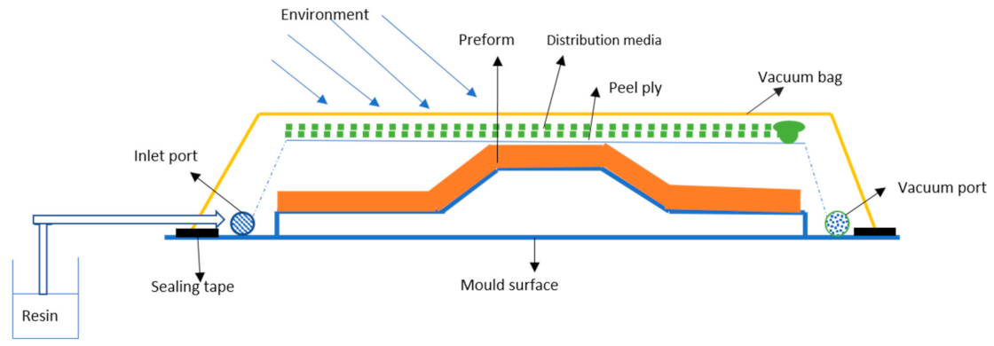
2. VARTM Process
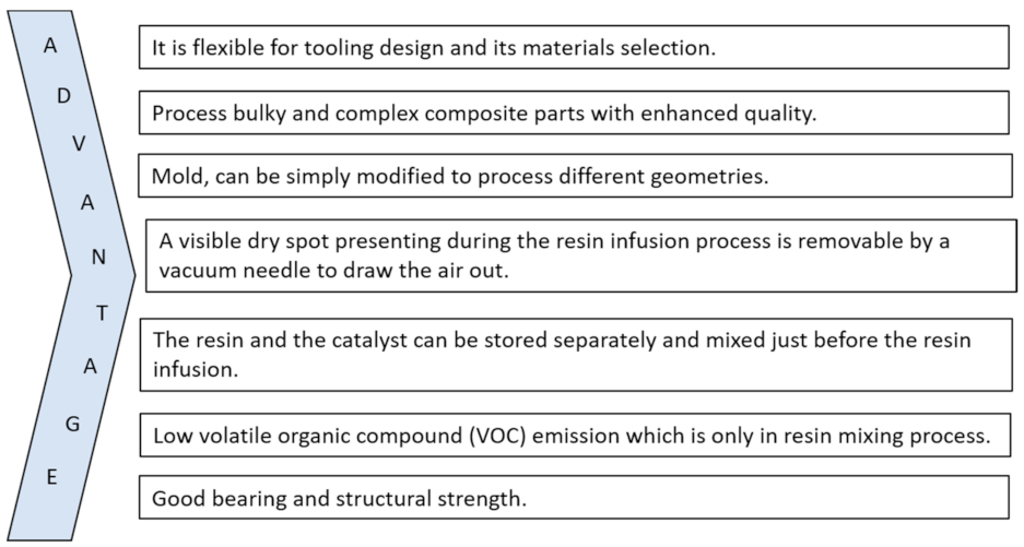
2.1. Advantage
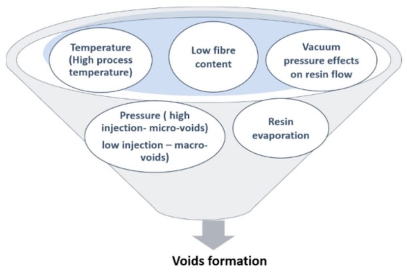
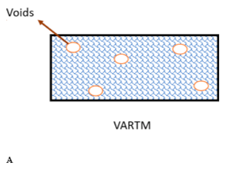
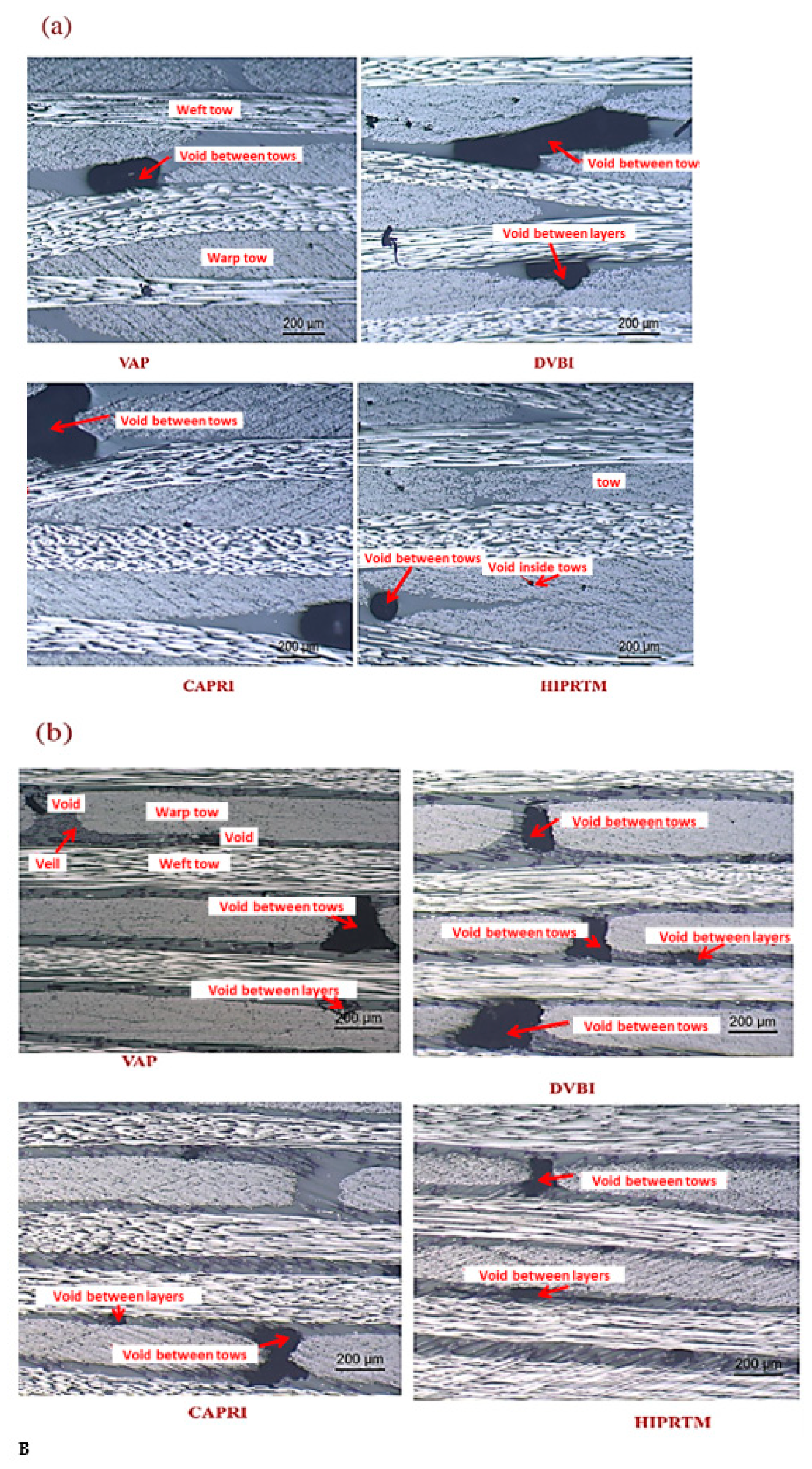
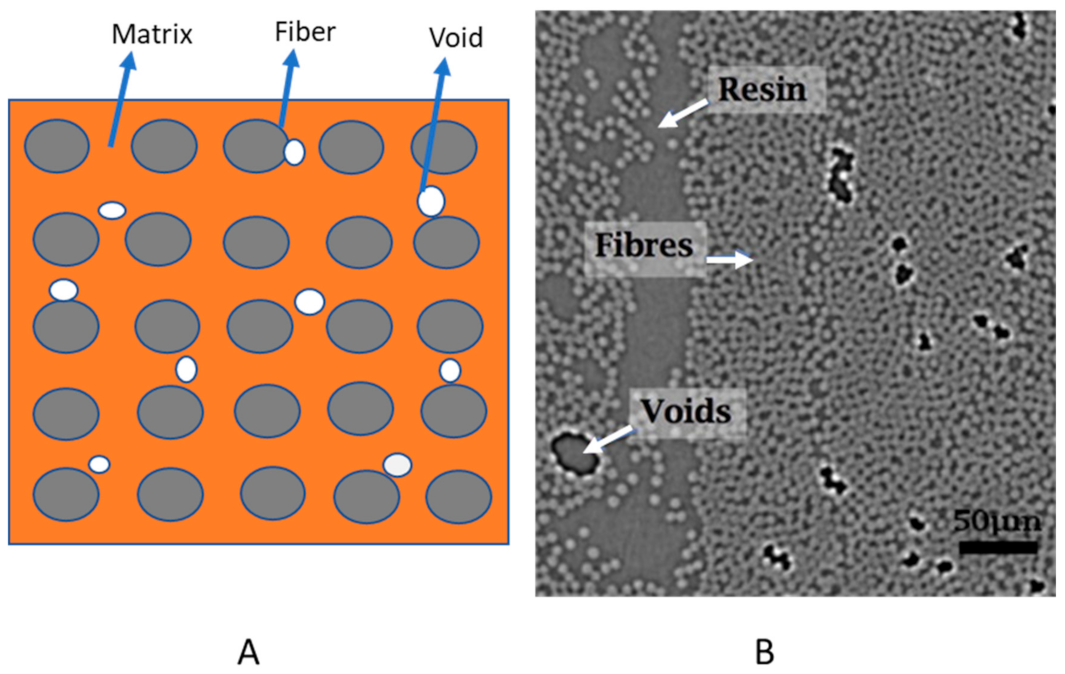
2.2. Defects in VARTM Processed Composites
3. Failure Theories
3.1. Failure Theories with Considering Manufacturing Defects (Voids)
3.2. Proposed Failure Criteria
3.2.1. Strain-Based Theory
Truncated Maximum Strain Criteria
3.2.2. Discrete Damage Mechanics (DDM)
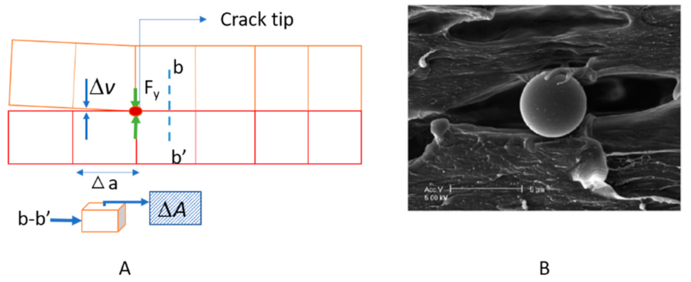
3.2.3. Fracture Mechanics (Virtual Crack Closure Technique (VCCT))
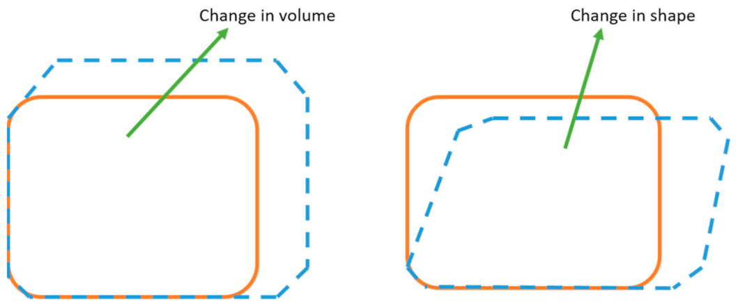
3.2.4. Micromechanics
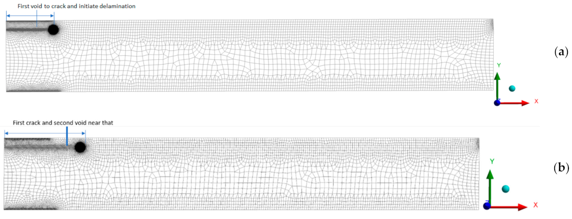
3.3. Example of Composite Laminate with Voids
4. Discussion
5. Conclusions
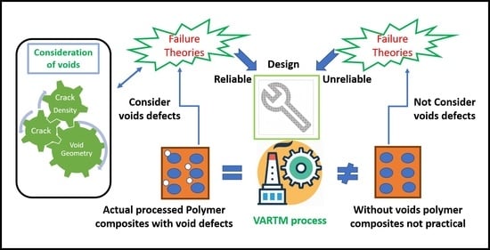
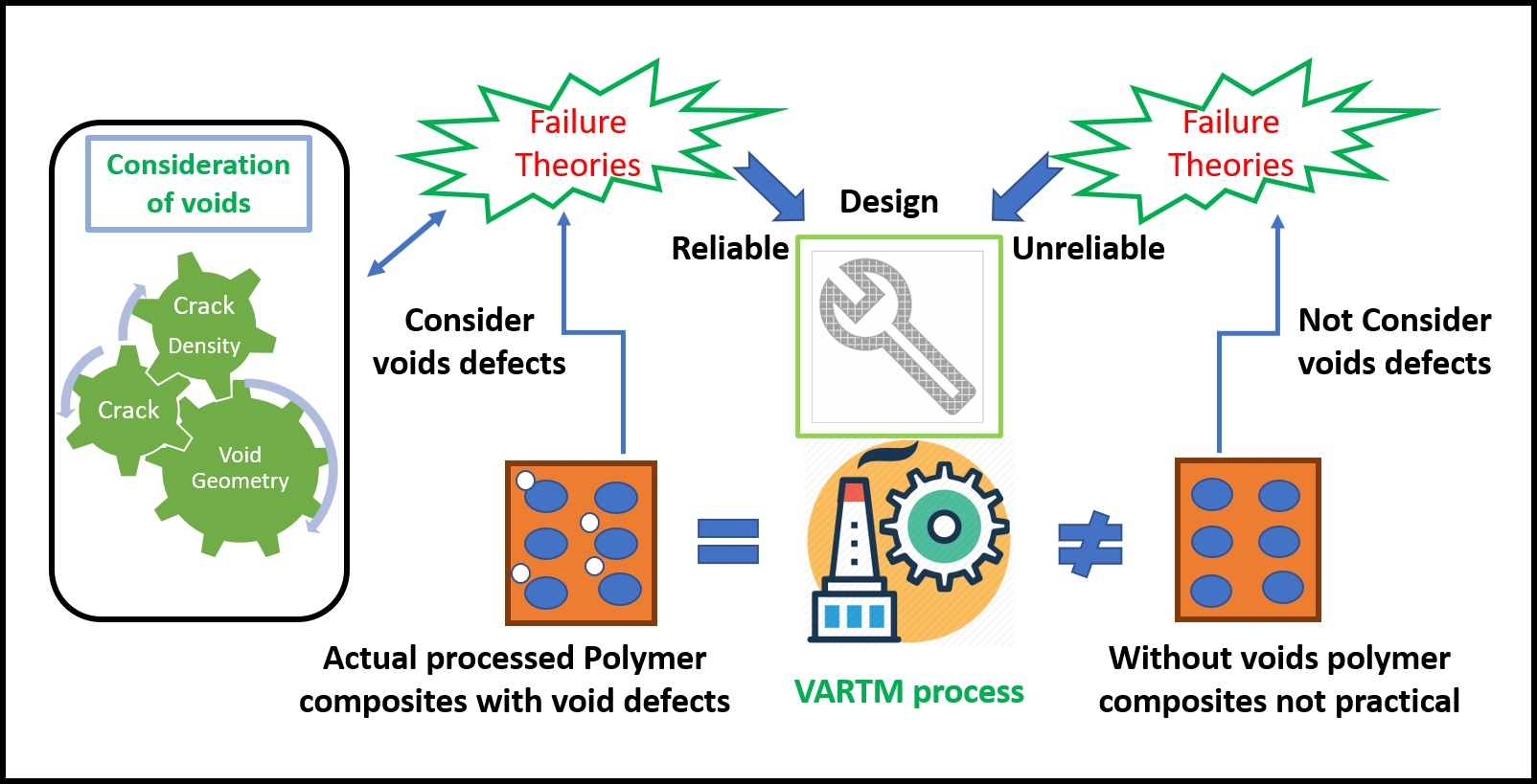
- Voids are significant defects in the composite manufacturing process (VARTM). Readers will understand the selection of failure theories in a cost-effective environment (mass-production) at the application level (working environment because different loading makes a different kind of failure) with the presence of voids.
- Voids to delamination should be considered at the time of design for composite laminates. Fracture mechanics-based VCCT failure estimation was proposed for the delamination study because it can consider the voids’ effect, enabling the energy release rate.
- Preliminary and damage level failure prediction is essential. Checking for preliminary level design viz. preliminary failure theories (TMSC) without considering damage behavior is enough then consideration of damage and crack behavior by DDM will be a good practice for precise understanding because DDM can consider voids by their density.
- Micromechanics with failure theory is also an excellent option to model defects (voids) for failure prediction at the micro-level and supporting a relation from micro to macro-level.
Author Contributions
Funding
Acknowledgments
Conflicts of Interest
References
- David Müzel, S.; Bonhin, E.P.; Guimarães, N.M.; Guidi, E.S. Application of the Finite Element Method in the Analysis of Composite Materials: A Review. Polymers 2020, 12, 818. [Google Scholar] [CrossRef]
- Hussain, N.N.; Regalla, S.P.; Rao, Y.V.D.; Dirgantara, T.; Gunawan, L.; Jusuf, A. Drop-weight impact testing for the study of energy absorption in automobile crash boxes made of composite material. Proc. Inst. Mech. Eng. Part L J. Mater. Des. Appl. 2020. [Google Scholar] [CrossRef]
- Dhimole, V.K.; Chen, Y.; Cho, C. Modeling and Two—Step Homogenization of Aperiodic Heterogenous 3D Four—Directional Braided Composites. J. Compos. Sci. 2020, 4, 179. [Google Scholar] [CrossRef]
- Hong, B.; Xian, G.; Li, H. Comparative study of the durability behaviors of epoxy- and polyurethane-based CFRP plates subjected to the combined effects of sustained bending and water/seawater immersion. Polymers 2017, 9, 603. [Google Scholar] [CrossRef]
- Bazli, M.; Ashrafi, H.; Jafari, A.; Zhao, X.L.; Singh Raman, R.K.; Bai, Y. Effect of fibers configuration and thickness on tensile behavior of GFRP laminates exposed to harsh environment. Polymers 2019, 11, 1401. [Google Scholar] [CrossRef] [PubMed]
- Rajak, D.K.; Pagar, D.D.; Menezes, P.L.; Linul, E. Fiber-reinforced polymer composites: Manufacturing, properties, and applications. Polymers 2019, 11, 1667. [Google Scholar] [CrossRef] [PubMed]
- Schubel, P.J. Cost modelling in polymer composite applications: Case study—Analysis of existing and automated manufacturing processes for a large wind turbine blade. Compos. Part B Eng. 2012, 43, 953–960. [Google Scholar] [CrossRef]
- McIlhagger, A.; Archer, E.; McIlhagger, R. 3-Manufacturing processes for composite materials and components for aerospace applications. In Soutis CBT-PC in the AI, 2nd ed.; Irving, P., Ed.; Woodhead Publishing: Sawston, UK, 2020; pp. 59–81. [Google Scholar] [CrossRef]
- Saleh Alghamdi, S.; John, S.; Roy Choudhury, N.; Dutta, N.K. Additive Manufacturing of Polymer Materials: Progress, Promise and Challenges. Polymers 2021, 13, 753. [Google Scholar] [CrossRef] [PubMed]
- Fidan, I.; Imeri, A.; Gupta, A.; Hasanov, S.; Nasirov, A.; Elliott, A.; Alifui-Segbaya, F.; Nanami, N. The trends and challenges of fiber reinforced additive manufacturing. Int. J. Adv. Manuf. Technol. 2019, 102, 1801–1818. [Google Scholar] [CrossRef]
- Mantelli, A.; Romani, A.; Suriano, R.; Diani, M.; Colledani, M.; Sarlin, E.; Turri, S.; Levi, M. UV-Assisted 3D Printing of Polymer Composites from Thermally and Mechanically Recycled Carbon Fibers. Polymers 2021, 13, 726. [Google Scholar] [CrossRef]
- Sunilpete, M.A.; Cadambi, R.M. Development of Cost Effective Out-of-Autoclave Technology—Vacuum Infusion Process with Tailored Fibre Volume Fraction. Mater. Today Proc. 2020, 21, 1293–1297. [Google Scholar] [CrossRef]
- Taylor, T.; Zhang, J.; Yanagimoto, J. Evaluation of a concept out-of-autoclave process for manufacturing carbon fibre reinforced polymer automotive parts. Procedia CIRP 2019, 86, 162–166. [Google Scholar] [CrossRef]
- Bodaghi, M.; Costa, R.; Gomes, R.; Silva, J.; Correia, N.; Silva, F. Experimental comparative study of the variants of high-temperature vacuum-assisted resin transfer moulding. Compos. Part A Appl. Sci. Manuf. 2020, 129, 105708. [Google Scholar] [CrossRef]
- Williams, C.; Summerscales, J.; Grove, S. Resin infusion under flexible tooling (RIFT): A review. Compos. Part A Appl. Sci. Manuf. 1996, 27, 517–524. [Google Scholar] [CrossRef]
- Summerscales, J.; Searle, T.J. Low-pressure (vacuum infusion) techniques for moulding large composite structures. Proc. Inst. Mech. Eng. Part L J. Mater. Des. Appl. 2005, 219, 45–58. [Google Scholar] [CrossRef]
- Sun, X.; Li, S.; Lee, L.J. Mold filling analysis in vacuum-assisted resin transfer molding. part I: SCRIMP based on a high-permeable medium. Polym. Compos. 1998, 19, 807–817. [Google Scholar] [CrossRef]
- Allende, M.; Mohan, R.V.; Walsh, S.M. Experimental and numerical analysis of flow behavior in the FASTRAC liquid composite manufacturing process. Polym. Compos. 2004, 25, 384–396. [Google Scholar] [CrossRef]
- Anderson, J.P.; Kelly, A.J.; Altan, M.C. Fabrication of Composite Laminates by Vacuum-Assisted Resin Transfer Molding Augmented with an Inflatable Bladder. In Proceedings of the 28th Annual Technical Conference American Society for Composites, State College, PA, USA, 9–11 September 2013; pp. 1283–1294. [Google Scholar]
- Amirkhosravi, M.; Pishvar, M.; Altan, M.C. Void reduction in VARTM composites by compaction of dry fiber preforms with stationary and moving magnets. J. Compos. Mater. 2019, 53, 769–782. [Google Scholar] [CrossRef]
- Yalcinkaya, M.A.; Sozer, E.M.; Altan, M.C. Fabrication of high quality composite laminates by pressurized and heated-VARTM. Compos. Part A Appl. Sci. Manuf. 2017, 102, 336–346. [Google Scholar] [CrossRef]
- van Oosterom, S.; Allen, T.; Battley, M.; Bickerton, S. An objective comparison of common vacuum assisted resin infusion processes. Compos. Part A Appl. Sci. Manuf. 2019, 125, 105528. [Google Scholar] [CrossRef]
- Aruniit, A.; Herranen, H.; Miller, K. Comparative study of the VARTM, VAP and MTI vacuum infusion processes. Key Eng. Mater. 2016, 674, 71–76. [Google Scholar] [CrossRef]
- Song, Y.S.; Youn, J.R. Numerical Investigation on Flow through Porous Media in the Post-infusion Process. Polym. Compos. 2008, 30, 1125–1131. [Google Scholar] [CrossRef]
- Kuentzer, N.; Simacek, P.; Advani, S.G.; Walsh, S. Correlation of void distribution to VARTM manufacturing techniques. Compos. Part A Appl. Sci. Manuf. 2007, 38, 802–813. [Google Scholar] [CrossRef]
- Kedari, V.R.; Farah, B.I.; Hsiao, K.T. Effects of vacuum pressure, inlet pressure, and mold temperature on the void content, volume fraction of polyester/e-glass fiber composites manufactured with VARTM process. J. Compos. Mater. 2011, 45, 2727–2742. [Google Scholar] [CrossRef]
- Mehdikhani, M.; Gorbatikh, L.; Verpoest, I.; Lomov, S.V. Voids in fiber-reinforced polymer composites: A review on their formation, characteristics, and effects on mechanical performance. J. Compos. Mater. 2019, 53, 1579–1669. [Google Scholar] [CrossRef]
- Mishnaevsky, L. Fiber Reinforced Composites: Numerical Analysis of Damage Initiation and Growth. In Computational Mesomechanics of Composites; John Wiley & Sons: Hoboken, NJ, USA, 2007; pp. 215–237. [Google Scholar] [CrossRef]
- Cantwell, W.J.; Morton, J. The significance of damage and defects and their detection in composite materials: A review. J. Strain. Anal. Eng. Des. 1992, 27, 29–42. [Google Scholar] [CrossRef]
- Nikopour, H. A virtual frame work for predication of effect of voids on transverse elasticity of a unidirectionally reinforced composite. Comput. Mater. Sci. 2013, 79, 25–30. [Google Scholar] [CrossRef]
- Xu, J.; Lu, X.; Zhu, X. Effect of Random Void Defects on the Mechanical Behavior of C/C Braided Composites. Adv. Eng. Mater. 2018, 20, 1–14. [Google Scholar] [CrossRef]
- Parnas, R.S.; Walsh, S.M. Vacuum-assisted resin transfer molding model. Polym. Compos. 2005, 26, 477–485. [Google Scholar] [CrossRef]
- Yang, B.J.; Ha, S.K.; Pyo, S.H.; Lee, H.K. Mechanical characteristics and strengthening effectiveness of random-chopped FRP composites containing air voids. Compos. Part B Eng. 2014, 62, 159–166. [Google Scholar] [CrossRef]
- Sevkat, E.; Brahimi, M. The bearing strength of pin loaded woven composites manufactured by Vacuum Assisted Resin Transfer Moulding and hand lay-up techniques. Procedia Eng. 2011, 10, 153–158. [Google Scholar] [CrossRef][Green Version]
- Bolick, R. Composite Fabrication via the VARTM Process; A&T State University: Greensboro, NC, USA, 2000. [Google Scholar]
- Wu, D.; Larsson, R.; Rouhi, M.S. Modeling and experimental validation of the VARTM process for thin-walled preforms. Polymers 2019, 11, 2003. [Google Scholar] [CrossRef]
- Federal Aviation Administration. Overview of Vacuum-Assisted Resin Transfer Molding Processing; U.S. Department of Transportation: New Jesrey, WA, USA, 2013. [Google Scholar]
- Heider, D.; Gillespie, J.W. VARTM Variability and Substantiation Information; University of Delware Center for Composite Materials: Newark, DE, USA, 2008. [Google Scholar]
- Uddin, N.; Vaidya, U.; Shohel, M.; Serrano-Perez, J.C. Cost-effective bridge girder strengthening using vacuum-assisted resin transfer molding (VARTM). Adv. Compos. Mater. 2004, 13, 255–281. [Google Scholar] [CrossRef]
- Chang, C.Y. Modeling and evaluation of the filling process of vacuum-assisted compression resin transfer molding. J. Polym. Eng. 2013, 33, 211–219. [Google Scholar] [CrossRef]
- Dong, C. Effects of Process-Induced Voids on the Properties of Fibre Reinforced Composites. J. Mater. Sci. Technol. 2016, 32, 597–604. [Google Scholar] [CrossRef]
- Liu, X.; Chen, F. A review of void formation and its effects on the mechanical performance of carbon fiber reinforced plastic. Eng. Trans. 2016, 64, 33–51. [Google Scholar]
- Norris, C.; McKinnon, P.F. Compression, Tension, and Shear Tests on Yellow-Poplar Plywood Panels of Sizes That Do Not Buckle with Tests Made at Various Angles to the Face Grain; U.S. Dept. of Agriculture, Forest Service, Forest Products Laboratory: Madison, WI, USA, 1956. [Google Scholar]
- Producers, B.R.; Bureau, N. A theory of the yielding and plastic flow of anisotropic metals. Proc. R. Soc. London Ser A Math. Phys. Sci. 1948, 193, 281–297. [Google Scholar] [CrossRef]
- Tsai, S.W.; Wu, E.M. A General Theory of Strength for Anisotropic Materials. J. Compos. Mater. 1971, 5, 58–80. [Google Scholar] [CrossRef]
- Hashin, Z. Failure Criteria for Unidirectional Fiber Composites. J. Appl. Mech. 1980, 47, 329–334. [Google Scholar] [CrossRef]
- Pang, S.S.; Pandian, A.; Bradshaw, R.D. Modified Tsai-Wu failure criterion for fiber-reinforced composite laminates. Polym. Compos. 1992, 13, 273–277. [Google Scholar] [CrossRef]
- Puck, A.; Deuschle, H.M. Progress in the Puck Failure Theory for Fibre Reinforced Composites: Analytical solutions for 3D-stress. Compos. Sci. Technol. 2002, 62, 371–378. [Google Scholar] [CrossRef]
- Puck, A.; Schürmann, H. Failure analysis of FRP laminates by means of physically based phenomenological models. Compos. Sci. Technol. 2002, 62, 1633–1662. [Google Scholar] [CrossRef]
- Lutz, G.; Getriebebau, V. The Puck theory of failure in laminates in the context of the new guideline VDI 2014 Part 3. In Proceedings of the Conference on Damage in Composite Materials, Stuttgart, Germany, 18–19 September 2006; pp. 1–12. [Google Scholar]
- Hinton, M.J.; Kaddour, A.S.; Soden, P.D. The World-Wide Failure Exercise. Its origin, concept and content. In Failure Criteria in Fibre-Reinforced-Polymer Composites; Elsevier: Amsterdam, The Netherlands, 2004; pp. 2–28. [Google Scholar] [CrossRef]
- Hinton, M.J.; Kaddour, A.S. The Second World-Wide Failure Exercise: Benchmarking of Failure Criteria Under Triaxial Stresses for Fibre-Reinforced Polymer Composites. In Proceedings of the 16th International Conference on Composite Materials, Kyoto, Japan, 8–13 July 2007. [Google Scholar]
- Kaddour, A.S.; Hinton, M.J.; Li, S.; Smith, P.A. The world-wide failure exercises: How can composites design and manufacture communities build their strength. In Proceedings of the 16th European Conference on Composite Materials, Seville, Spain, 22–26 June 2014. [Google Scholar]
- Echaabi, J.; Trochu, F.; Gauvin, R. Review of Failure Criteria of Fibrous Composite Materials. Polym. Compos. 1996, 17, 786–798. [Google Scholar] [CrossRef]
- De Luca, A.; Caputo, F. A review on analytical failure criteria for composite materials. AIMS Mater. Sci. 2017, 4, 1165–1185. [Google Scholar] [CrossRef]
- De Saint-Venant, M. Memoire sur la Torsion des Prismes; Imprimerie Nationale: Paris, France, 1855. [Google Scholar]
- Misses, R.V. On Saint Venant’s principle. Bull. Am. Math. Soc. 1945, 51, 555–562. [Google Scholar] [CrossRef]
- Collins, J.A. Maximum Normal Stress Theory (Rankine’s Theory), 2nd ed.; Fail. Mater. Mech. Des. Anal. Predict. Prev.; Wiley: New York, NY, USA, 1993; p. 672. [Google Scholar]
- Rankine, W.J.M. On the stability of loose earth. Philos. Trans. R. Soc. Lond. 1857, 147, 9–27. [Google Scholar]
- Griffits, A.A. The phenomena of rupture and flow in solids. Philos. Trans. R. Soc. 1921, 221, 163–198. [Google Scholar] [CrossRef]
- Irwin, G.R. Analysis of Stresses and Strains near the End of a crack Trav-ersing a Plate. J. Appl. Mech. 1957, 24, 361–364. [Google Scholar]
- Dugdale, D.S. Yielding of steel sheets containing slits. J. Mech. Phys. Solids 1960, 8, 100–104. [Google Scholar] [CrossRef]
- Tsai, S.W. Strength Characteristics of Composite Materials; Philco Corporation: Newport Beach, CA, USA, 1965. [Google Scholar] [CrossRef]
- Hoffman, O. The Brittle Strength of Orthotropic Materials. J. Compos. Mater. 1967, 1, 200–206. [Google Scholar] [CrossRef]
- Whitney, J.M.; Nuismer, R.J. Stress Fracture Criteria for Laminated Composites Containing Stress Concentrations. J. Compos. Mater. 1974, 8, 253–265. [Google Scholar] [CrossRef]
- Mast, P.W.; Nash, G.E.; Michopoulos, J.G.; Thomas, R.; Badaliance, R.; Wolock, I. Characterization of strain-induced damage in composites based on the dissipated energy density part I. Basic scheme and formulation. Theor. Appl. Fract. Mech. 1995, 22, 71–96. [Google Scholar] [CrossRef]
- Mast, P.W.; Nash, G.E.; Michopoulos, J.G.; Thomas, R.; Badaliance, R.; Wolock, I. Characterization of strain-induced damage in composites based on the dissipated energy density Part III. General material constitutive relation. Theor. Appl. Fract. Mech. 1995, 22, 115–125. [Google Scholar] [CrossRef]
- Edge, E.C. Stress-based Grant-Sanders method for predicting failure of composite laminates. In Fail Criteria Fibre-Reinforced-Polymer Composites; Elsevier: Amsterdam, The Netherlands, 2004; Volume 3538, pp. 140–156. [Google Scholar] [CrossRef]
- Christensen, R.M. Stress based yield/failure criteria for fiber composites. Int. J. Solids Struct. Struct. 1997, 34, 529–543. [Google Scholar] [CrossRef]
- Cuntze, R.G. “Fracture-Type Strentgh Criteria” Formulated by Invariants Which Consider the Material Symmetries of the Isotropic/Amisotropic Material Used. In Spacecraft Structures, Materials and Mechanical Engineering; European Space Agency: Noordwijk, The Netherlands, 1996; Volume 386, p. 399. [Google Scholar]
- Eckold, G.C. Failure criteria for use in the design environment. Compos. Sci. Technol. 1998, 58, 1095–1105. [Google Scholar] [CrossRef]
- Wolfe, W.E.; Butalia, T.S. A strain-energy based failure criterion for non-linear analysis of composite laminates subjected to biaxial loading. Compos. Sci. Technol. 1996, 58, 1107–1124. [Google Scholar] [CrossRef]
- Butalia, T.S.; Wolfe, W.E. A strain-energy-based non-linear failure criterion: Comparison of numerical predictions and experimental observations for symmetric composite laminates. Compos. Sci. Technol. 2002, 62, 1697–1710. [Google Scholar] [CrossRef]
- Zand, B.; Butalia, T.S.; Wolfe, W.E.; Schoeppner, G.A. A strain energy based failure criterion for nonlinear analysis of composite laminates subjected to triaxial loading. J. Compos. Mater. 2012, 46, 2515–2537. [Google Scholar] [CrossRef]
- Gosse, J.H.; Christensen, S. Strain invariant failure criteria for polymers in composite materials. In Proceedings of the 19th AIAA Applied Aerodynamics Conference, Anaheim, CA, USA, 11–14 June 2001. [Google Scholar] [CrossRef]
- Yeh, H.L.; Yeh, H.Y. The modified quadric surfaces criterion for composite materials. J. Reinf. Plast. Compos. 2002, 21, 277–289. [Google Scholar] [CrossRef]
- McCartney, L.N. Physically based damage models for laminated composites. Proc. Inst. Mech. Eng. Part L J. Mater. Des. Appl. 2003, 217, 163–199. [Google Scholar] [CrossRef]
- Bogetti, T.A.; Hoppel, C.P.R.; Harik, V.M.; Newill, J.F.; Burns, B.P. Predicting the nonlinear response and progressive failure of composite laminates. Compos. Sci. Technol. 2004, 64, 329–342. [Google Scholar] [CrossRef]
- Tay, T.E.; Tan, S.H.N.; Tan, V.B.C.; Gosse, J.H. Damage progression by the element-failure method (EFM) and strain invariant failure theory (SIFT). Compos. Sci. Technol. 2005, 65, 935–944. [Google Scholar] [CrossRef]
- Hart-Smith, L.J. Application of the strain invariant failure theory (SIFT) to metals and fiber-polymer composites. Philos. Mag. 2010, 90, 4263–4331. [Google Scholar] [CrossRef]
- Chamis, C.C. Failure Criteria for Filamentary Composites. In Composite Materials. Testing and Design; Yurenka, S., Ed.; ASTM International: West Conshohocken, PA, USA, 1969; pp. 336–351. [Google Scholar] [CrossRef]
- Varna, J.; Joffe, R.; Berglund, L.A.; Lundström, T.S. Effect of voids on failure mechanisms in RTM laminates. Compos. Sci. Technol. 1995, 53, 241–249. [Google Scholar] [CrossRef]
- Jeong, H. Effects of voids on the mechanical strength and ultrasonic attenuation of laminated composites. J. Compos. Mater. 1997, 31, 276–292. [Google Scholar] [CrossRef]
- Colavito, K.W.; Kilic, B.; Celik, E.; Madenci, E.; Askari, E.; Silling, S. Effect of void content on stiffness and strength of composites by a peridynamic analysis and static indentation test. In Proceedings of the AIAA/ASME/ASCE/AHS/ASC Structures Structural Dynamics and Materials Conference, Honolulu, Hawaii, 23–26 April 2007; Volume 7, pp. 6691–6701. [Google Scholar]
- Ricotta, M.; Quaresimin, M.; Talreja, R. Mode I Strain Energy Release Rate in composite laminates in the presence of voids. Compos. Sci. Technol. 2008, 68, 2616–2623. [Google Scholar] [CrossRef][Green Version]
- Chowdhury, K.A.; Talreja, R.; Benzerga, A.A. Effects of manufacturing-induced voids on local failure in polymer-based composites. J. Eng. Mater. Technol. Trans ASME 2008, 130, 0210101–02101019. [Google Scholar] [CrossRef]
- Zhuang, L. Effects Of Voids On Delamination Growth In Composite Laminates Under Compression. Master’s Thesis, A&M University, College Station, TX, USA, 2012. [Google Scholar]
- Talreja, R. Studies on the failure analysis of composite materials with manufacturing defects. Mech. Compos. Mater. 2013, 49, 35–44. [Google Scholar] [CrossRef]
- Shigang, A.; Daining, F.; Rujie, H.; Yongmao, P. Effect of manufacturing defects on mechanical properties and failure features of 3D orthogonal woven C/C composites. Compos. Part B Eng 2015, 71, 113–121. [Google Scholar] [CrossRef]
- Suhot, M.A.; Chambers, A.R. The effects of voids on the flexural properties and failure mechanisms of carbon/epoxy composites. J. Teknol. 2014, 71, 151–157. [Google Scholar] [CrossRef]
- Liu, H.; Cui, H.; Wen, W.; Su, X.; Kang, H.; Engler-Pinto, C. The effect of voids on the quasi-static tensile properties of carbon fiber/polymer-laminated composites. J. Compos. Mater. 2018, 52, 1997–2015. [Google Scholar] [CrossRef]
- Sudhir, A.; Talreja, R. Simulation of manufacturing induced fiber clustering and matrix voids and their effect on transverse crack formation in unidirectional composites. Compos. Part A Appl. Sci. Manuf. 2019, 127, 105620. [Google Scholar] [CrossRef]
- Xu, L.; Huang, Y. Effects of Voids on Concrete Tensile Fracturing: A Mesoscale Study. Adv. Mater. Sci. Eng. 2017, 2017. [Google Scholar] [CrossRef]
- Jiang, H.; Ren, Y.; Liu, Z.; Zhang, S. Microscale finite element analysis for predicting effects of air voids on mechanical properties of single fiber bundle in composites. J. Mater. Sci. 2019, 54, 1363–1381. [Google Scholar] [CrossRef]
- Sun, Q.; Guo, H.; Zhou, G.; Meng, Z.; Chen, Z.; Kang, H.; Keten, S.; Su, X. Experimental and computational analysis of failure mechanisms in unidirectional carbon fiber reinforced polymer laminates under longitudinal compression loading. Compos. Struct. 2018, 203, 335–348. [Google Scholar] [CrossRef]
- Hyde, A.; He, J.; Cui, X.; Lua, J.; Liu, L. Effects of microvoids on strength of unidirectional fiber-reinforced composite materials. Compos. Part B Eng. 2020, 187, 107844. [Google Scholar] [CrossRef]
- Hyde, A.; Liu, L.; Cui, X.; Lua, J. Micromechanics-enriched finite element modeling of composite structures with fiber waviness and void defects. In Proceedings of the AIAA SciTech Forum, San Diego, CA, USA, 7–11 January 2019; pp. 1–12. [Google Scholar] [CrossRef]
- Donadon, M.V.; de Almeida, S.F.M.; Arbelo, M.A.; de Faria, A.R. A Three-Dimensional Ply Failure Model for Composite Structures. Int. J. Aerosp. Eng. 2009, 2009, 1–22. [Google Scholar] [CrossRef]
- Hart-Smith, L.J. Predictions-of-the-original-and-truncated-maximum-strain-failure-models-for-certain-fibrous-composite-laminates. Compos. Sci. Technol. 1998, 58, 1151–1178. [Google Scholar] [CrossRef]
- Hart-Smith, L.J. The truncated maximum strain composite failure model. Composites 1993, 24, 587–591. [Google Scholar] [CrossRef]
- Talreja, R. Continuum Mechanics Characterization of Damage in Composite Materials. Proc. R. Soc. London Ser. A Math. Phys. Sci. 1985, 399, 195–216. [Google Scholar] [CrossRef]
- Swindeman, M.J.; Iarve, E.V.; Brockman, R.A.; Mollenhauer, D.H.; Hallett, S.R. Strength prediction in open hole composite laminates by using discrete damage modeling. AIAA J. 2013, 51, 936–945. [Google Scholar] [CrossRef]
- Barbero, E.J.; Lonetti, P. An Inelastic Damage Model for Fiber Reinforced Laminates. J. Compos. Mater. 2002, 36, 941–962. [Google Scholar] [CrossRef]
- Moure, M.M.; García-Castillo, S.K.; Sánchez-Sáez, S.; Barbero, E.; Barbero, E.J. Influence of ply cluster thickness and location on matrix cracking evolution in open-hole composite laminates. Compos. Part B Eng. 2016, 95, 40–47. [Google Scholar] [CrossRef]
- Hahn, H.T.; Erikson, J.B.; Tsai, S.W. Characterization of Matrix/Interface-Controlled Strength of Unidirectional Composites. In Fracture of Composite Materials; Springer: Berlin/Heidelberg, Germany, 1982; pp. 197–214. [Google Scholar] [CrossRef]
- Kosteski, L.; Barrios D’Ambra, R.; Iturrioz, I. Crack propagation in elastic solids using the truss-like discrete element method. Int. J. Fract. 2012, 174, 139–161. [Google Scholar] [CrossRef]
- Moure, M.M.; Sanchez-Saez, S.; Barbero, E.; Barbero, E.J. Analysis of damage localization in composite laminates using a discrete damage model. Compos. Part B Eng. 2014, 66, 224–232. [Google Scholar] [CrossRef]
- Rybicki, E.F.; Kanninen, M.F. A finite element calculation of stress intensity factors by a modified crack closure integral. Eng. Fract. Mech. 1977, 9, 931–938. [Google Scholar] [CrossRef]
- Gliszczynski, A.; Samborski, S.; Wiacek, N.; Rzeczkowski, J. Mode I interlaminar fracture of glass/epoxy unidirectional laminates. Part II: Numerical analysis. Materials 2019, 12, 1604. [Google Scholar] [CrossRef] [PubMed]
- Cairns, D.S.; Nelson, J.W.; Woo, K.; Miller, D. Progressive damage analysis and testing of composite laminates with fiber waves. Compos. Part A Appl. Sci. Manuf. 2016, 90, 51–61. [Google Scholar] [CrossRef]
- Thio, Y.S.; Argon, A.S.; Cohen, R.E. Role of interfacial adhesion strength on toughening polypropylene with rigid particles. Polymer 2004, 45, 3139–3147. [Google Scholar] [CrossRef]
- Zhuang, L.; Talreja, R. Effects of voids on postbuckling delamination growth in unidirectional composites. Int. J. Solids Struct. 2014, 51, 936–944. [Google Scholar] [CrossRef]
- Krueger, R. Virtual crack closure technique: History, approach, and applications. Appl. Mech. Rev. 2004, 57, 109–143. [Google Scholar] [CrossRef]
- Raju, I.S. Calculation of strain-energy release rates with higher order and singular finite elements. Eng. Fract. Mech. 1987, 28, 251–274. [Google Scholar] [CrossRef]
- Valvo, P.S. A revised virtual crack closure technique for physically consistent fracture mode partitioning. Int. J. Fract. 2011, 173, 1–20. [Google Scholar] [CrossRef]
- Elnekhaily, S.A.; Talreja, R. Damage initiation in unidirectional fiber composites with different degrees of nonuniform fiber distribution. Compos. Sci. Technol. 2018, 155, 22–32. [Google Scholar] [CrossRef]
- Marcon, E.; Puech, F. Generalizing Ripley’s K Function to Inhomogeneous Populations; Halshs: Lyon, France, 2009. [Google Scholar]
- Scott, A.E.; Sinclair, I.; Spearing, S.M.; Mavrogordato, M.N.; Hepples, W. Influence of voids on damage mechanisms in carbon/epoxy composites determined via high resolution computed tomography. Compos. Sci. Technol. 2014, 90, 147–153. [Google Scholar] [CrossRef]
- Sudhir, A.; Talreja, R. The combined effect of fiber distribution irregularities and matrix voids on failure initiation in polymer matrix composites. In Proceedings of the 32nd Technical Conference of the American Society for Composites, West Lafayette, IN, USA, 23–25 October 2017. [Google Scholar] [CrossRef]
- Yudhanto, A. Effects Of Micromechanical Factors in The Strain Invariant Failure Theory for Composites. Master’s Thesis, National University of Singapore, Singapore, 2005. [Google Scholar]
- Goyal, V.K.; García, C.I.; Irizarry, E. Damage initiation in isotropic and composites structures using strain invariant failure theory. In Proceedings of the 57th AIAA/ASCE/AHS/ASC Structures, Structural Dynamics and Materials Conference, San Diego, CA, USA, 4–8 January 2016. [Google Scholar] [CrossRef]


| Process | Pre-Infusion | Infusion | Post-Infusion |
| • Mold preparation • Material placement (fiber reinforcement) • Maintain flow distribution medium, injection port, vent port, vacuum bag against the sealing tap • Debulking process (optional) | • apply the vacuum inside the bagged preform assembly • Fill the resin into the resin reservoir. Keep the vacuum port on | • Close the injection port • After curing resin, turn off the vacuum then demold the composite part | |
| Defects (Voids) reason | • Moisture in resin • Resin mixing and degassing and bag integrity • Leak rate | • Resin flow, pressure, flow timing, and thickness management | • Injection and vacuum off timing, • demolding conditions |
| Author, Year | Research Approach/ Failure Theory | Advantage | Disadvantage | Remark |
|---|---|---|---|---|
| St. Venant, 1855 [56,57] | Maximum strain failure theory | Simple to use because of direct comparison with ultimate strain | Non-interactive and developed for isotropic cases | Strain based criteria |
| Rankine, 1857 [58,59] | Maximum stress failure theory | Simple to use because of direct comparison with ultimate stress | Non-interactive and developed for isotropic cases | Stress based criteria |
| Griffith, 1920 [60] | Linear elastic fracture mechanics | First fracture theory based on energy release rate (g criteria belongs) | Developed for isotropic material and limited for a single crack, no nucleation accounted | Brittle fracture (strength depends on the size of cracks) |
| Norris, 1946 [43] | Second power interaction formula for ultimate strength | Consider orthotropic material | Very basic formulation as von-mises and Bauschinger effect was not accounted | Plywood (tension-compression and shear test) |
| RHill,1948 [44] | Polynomial criteria extension of von mises | Included more term for accuracy and generalization of a Hubris-Mises criterion | No. of unknowns were more, and no Bauschinger effect considered | Yielding and plastic flow of an anisotropic metal. |
| Irwin fracture theory, 1957 [61] | Plastic zone consideration in fracture mechanics | Extended Griffith theory, and related to the concept of crack intensity factor | Firstly extended for quasi-brittle materials and no nucleation of a crack | Extend Griffith to ductile for plastic zone consideration |
| Dugdale’s Model, 1960 [62] | Elastic-perfectly plastic Tresca yield criteria | For damage cohesive energy-based model capable of nucleation of the crack | Parameters are dependent on hit and trail, based on remeshing and predefined area of the crack | Cohesive zone model |
| Tsai, 1965 [63] | Quadratic function of stress | Interactive theory covered laminated effect | No Bauschinger effect accounted | Extension of distortion theory for anisotropic material |
| Hoffman, 1967 [64] | Fracture condition | Adopted Phenomenological fracture conditions | validity range is limited for material groups, i.e., brittles | Hill’s yield condition(extension) |
| Tsai-wu, 1971 [45] | Polynomial (interactive) | Interactive and most valid among polynomial criteria | The interaction term needs experimentations | Scale function of two strength tensor |
| Whitney-Nuismer failure criterion, 1974 [65] | Tensile strength and characteristic dimension (different then linear elastic fracture mechanics (LEFM)) | Failure prediction along with the thickness of the laminate | Limited to certain features and geometries | Stress based criteria |
| Hashin, 1980 [46] | Quadratic stress polynomial | Considered different failure modes of fiber and matrix | Certified for unidirectional and specific loadings only | Failure mode |
| P.W.Mast 1995 (I,II,III), [66,67] | Energy density approach | Damage estimation by the dissipation of energy so internal failure can capture | Specified for submarine structures | Strain-induced damage |
| Puck, 1969 and 1996 [49] | Fiber and inter-fiber failure mode | Various failure mode can be obtained | Discontinuities for different load combinations and failure modes are non-fatal | Physically-based failure criteria |
| Edge, 1996 [68] | Grant sanders method | Ply by ply failure estimation, mode and location can cover, discrete failure phenomena | Discriminations in high strain condition and matrix-subjected configurations | Stress based criteria |
| Christensen theory, 1997 [69] | Matrix (mode I) and fiber (mode II) dominated failure | Two modes for fiber ad matrix dominated composites with micromechanics hints | Particularly specified for polymer composites | Stress based criteria yield |
| Cuntze, 1997 [70] | Inter fiber failure mode and internal friction values | Covered a large variety of fracture and failure with micro and macro-level | The modeling of some invariants are tricky, and probabilistic terms were used | Invariant failure mode concept |
| Eckold, 1998 [71] | Pragmatic approach (Design environment) | Failure definition in design condition with initial failure | The approach was application-specific, and design was based on assumptions | Based on application problem to tackle design |
| Butalia, 1996,2001,2012 [72,73,74] | Maximum strain progressive laminate failure ply discount method | New strain energy-based failure method with lamination consideration | Specified for particular loading conditions | Strain energy-based criteria |
| Gosse, 2001 [75] | SIFT (Strain invariant failure criteria) | Covered wide range with the effect of volumetric and equivalent strain, included micro-level consideration | Developed for polymer composites and assumed that both failure modes (fibers and matrix) are independent | Strain based criteria |
| Yeh,2002 [76] | Quadric surfaces criterion (biaxial test has reduced) | Extension of Tsai-wu polynomial criteria and no bi-axial test needed | Specified for certain loading cases | Strain based criteria |
| McCartney, 2003 [77] | Assessment of failure criteria | Proposed crack prediction model | Applicable for specific cases and reliable only in mode I cracking | Physically-based damage model |
| Bogetti, 2004 [78] | Progressive laminate failure (maximum principal strain and ply discount) | Progressive failure in laminate with non-linear considerations | Specific for particular loading conditions | Strain based criteria |
| Tay, 2005 [79] | Element failure method (damage progression) | SIFT theory extended with element failure concept for damage progression, delamination, and considered micro-level details | Verified for the certain load cases | Strain based criteria |
| Hart-Smith, 2010 [80] | SIFT (for metal and polymer composite) | SIFT extended for metals | There are already well-defined criteria for metals, no specific need | Strain based criteria |
| Suggested Failure Theories | Reason of Suggestion |
|---|---|
| Discrete damage mechanics [103] | Advance level design to consider crack/void density for analysis, and the main advantage is mesh independent. |
| Fracture mechanics (VCCT) [113] | To estimate voids growth to delamination (delamination approach). The pre-meshing definition can model voids. |
| Micromechanics [97,119] | To capture micro-level to macro-level failure with modeled voids which can capture microvoids as well. |
| TMSC and SIFT [75,99] | For a primarily level design checking strain-based TMSC approach is suggested because stress is effected due to change in young modulus in case of voids. SIFT is a strain-based and micromechanics included criterion, which add details from micro to macro-level. |
Publisher’s Note: MDPI stays neutral with regard to jurisdictional claims in published maps and institutional affiliations. |
© 2021 by the authors. Licensee MDPI, Basel, Switzerland. This article is an open access article distributed under the terms and conditions of the Creative Commons Attribution (CC BY) license (http://creativecommons.org/licenses/by/4.0/).
Share and Cite
Dhimole, V.K.; Serrao, P.; Cho, C. Review and Suggestion of Failure Theories in Voids Scenario for VARTM Processed Composite Materials. Polymers 2021, 13, 969. https://doi.org/10.3390/polym13060969
Dhimole VK, Serrao P, Cho C. Review and Suggestion of Failure Theories in Voids Scenario for VARTM Processed Composite Materials. Polymers. 2021; 13(6):969. https://doi.org/10.3390/polym13060969
Chicago/Turabian StyleDhimole, Vivek Kumar, Pruthvi Serrao, and Chongdu Cho. 2021. "Review and Suggestion of Failure Theories in Voids Scenario for VARTM Processed Composite Materials" Polymers 13, no. 6: 969. https://doi.org/10.3390/polym13060969
APA StyleDhimole, V. K., Serrao, P., & Cho, C. (2021). Review and Suggestion of Failure Theories in Voids Scenario for VARTM Processed Composite Materials. Polymers, 13(6), 969. https://doi.org/10.3390/polym13060969