
A Review of Vat Photopolymerization Technology: Materials, Applications, Challenges, and Future Trends of 3D Printing


Abstract
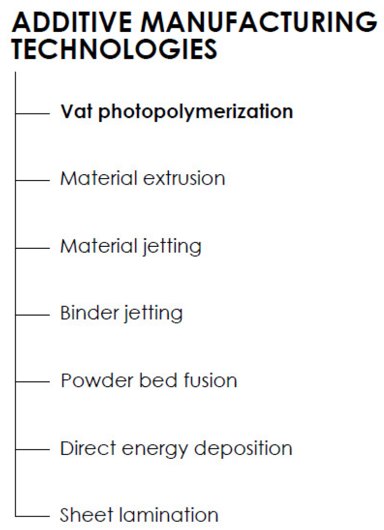
1. Introduction
2. Vat Photopolymerization
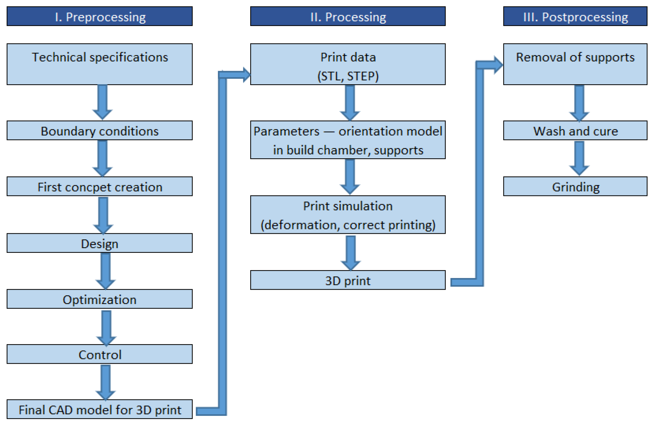
2.1. 3D Printing Process
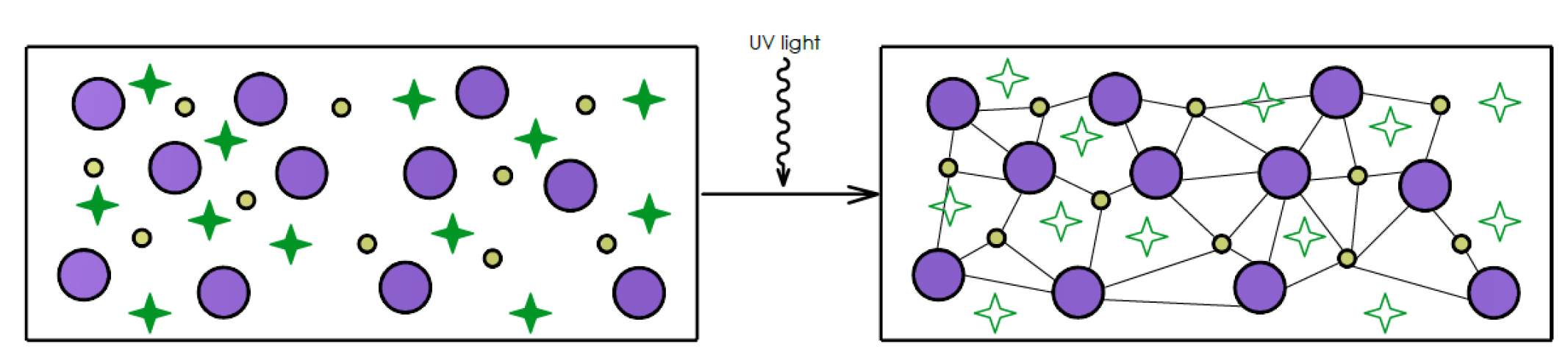
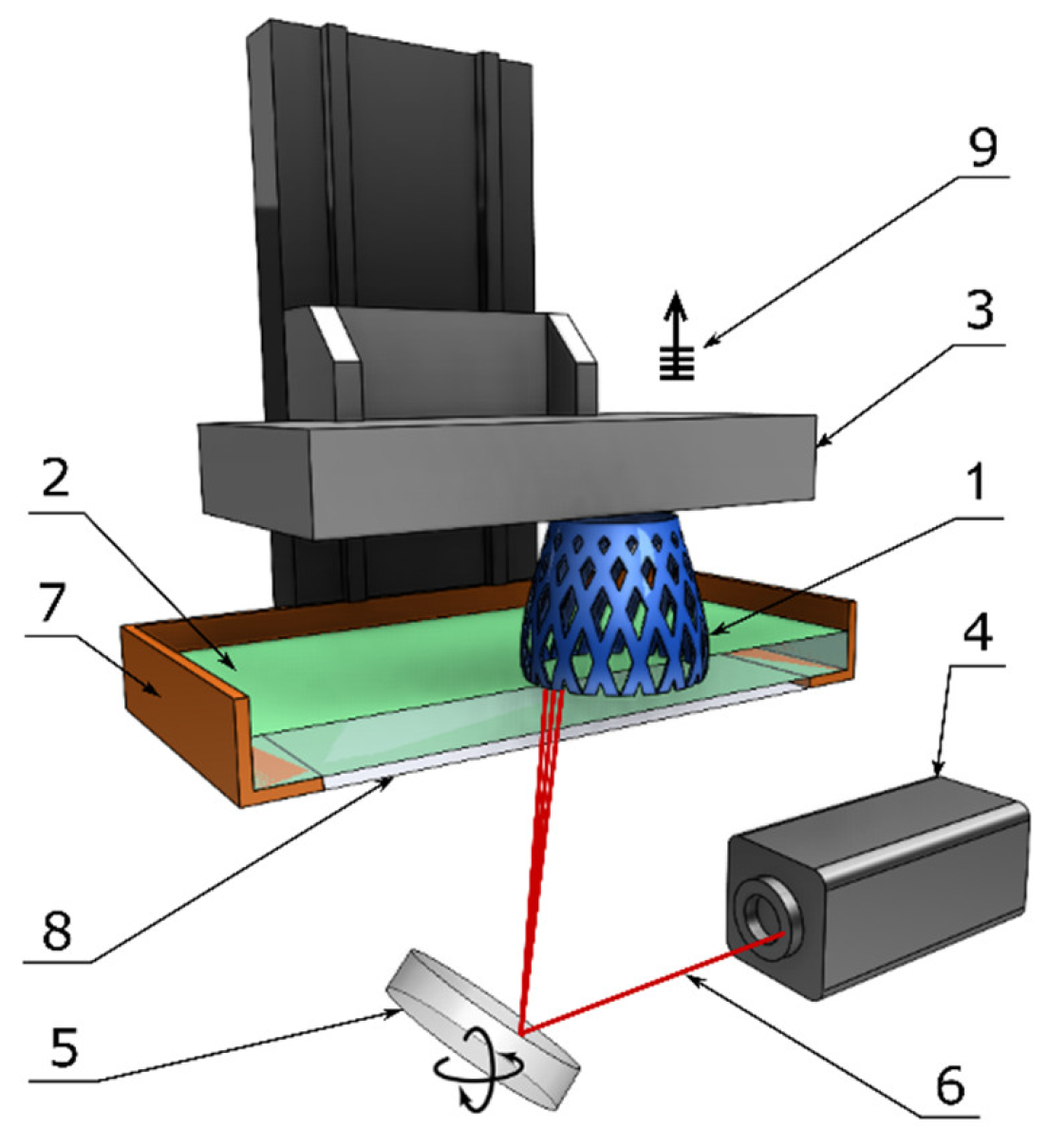
2.2. Printing Principle of Photopolymerization
2.3. Classification
2.3.1. Stereolithography
2.3.2. Digital Light Processing
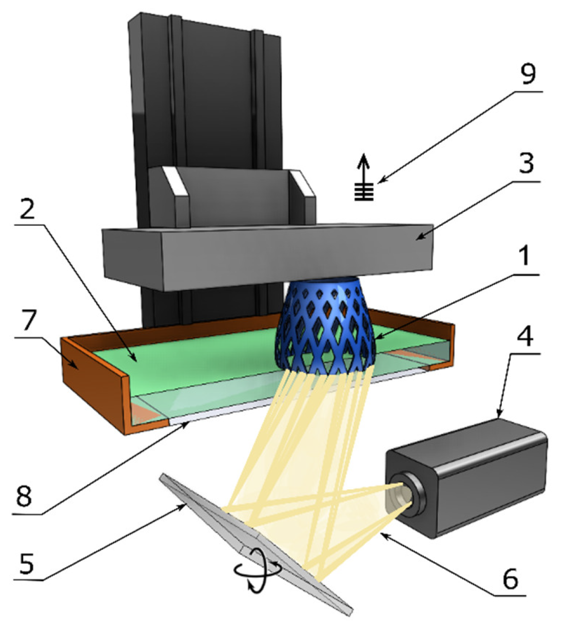
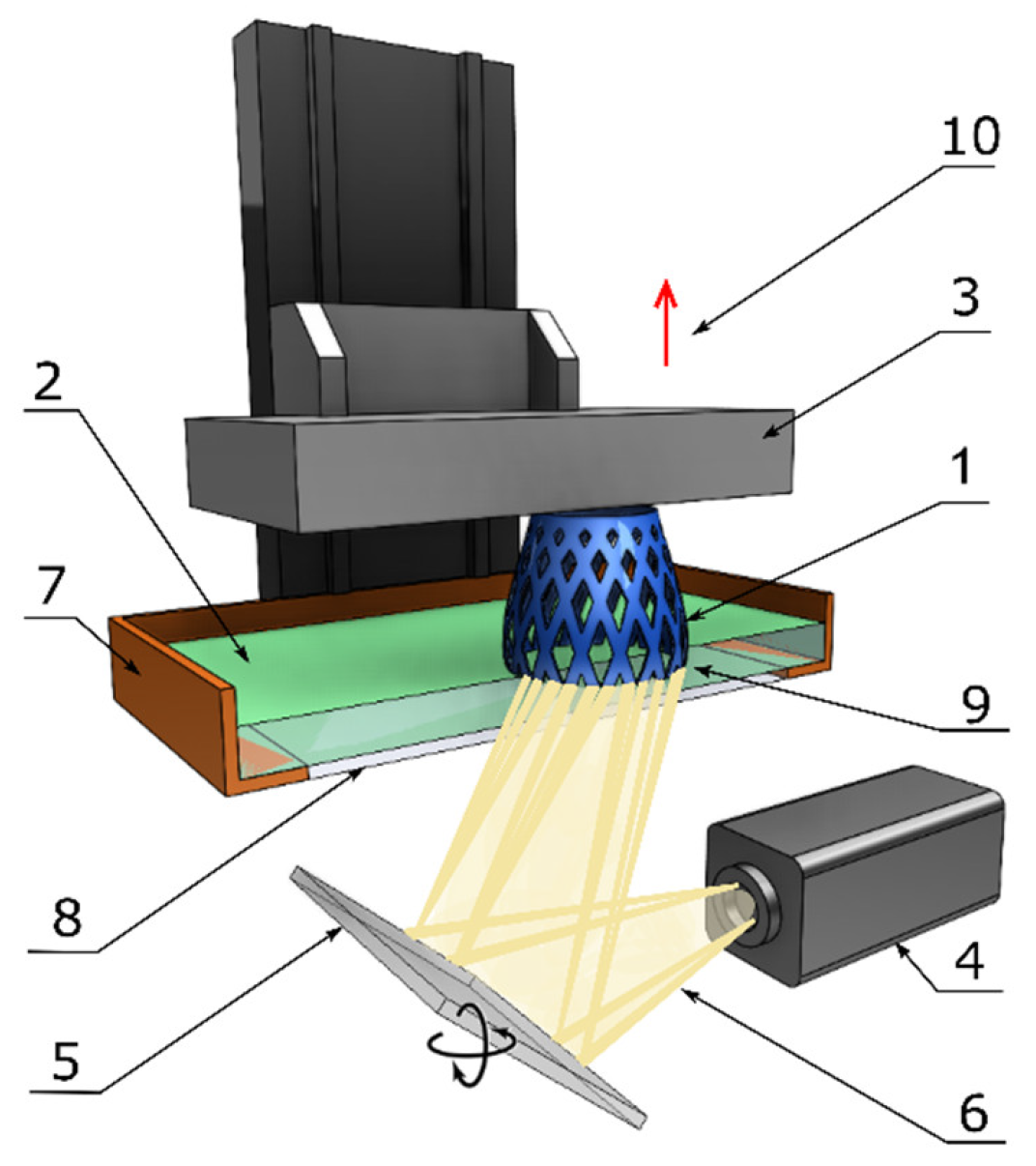
2.3.3. Continuous Digital Light Processing/Continuous Liquid Interface Production
2.3.4. Two-Photon Lithography (2PL)
2.4. Accuracy
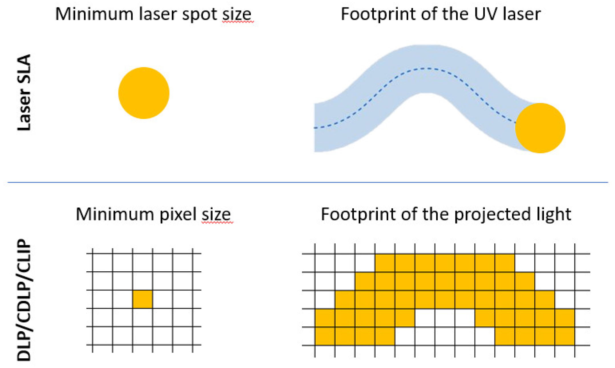
2.4.1. Accuracy Comparison between SLA, DLP, and CDLP/CLIP
2.4.2. Accuracy of 2PL
3. Photopolymer Material Classification
3.1. Standard Resin
3.2. Structural Resin
3.3. Tough and Durable Resin
3.4. Elastic and Flexible Resin
3.5. Ceramic and Castable Wax Resin
3.6. Biocompatible Resin
3.7. Bioink
3.8. Photoresist for Two-Photon Lithography
4. Applications
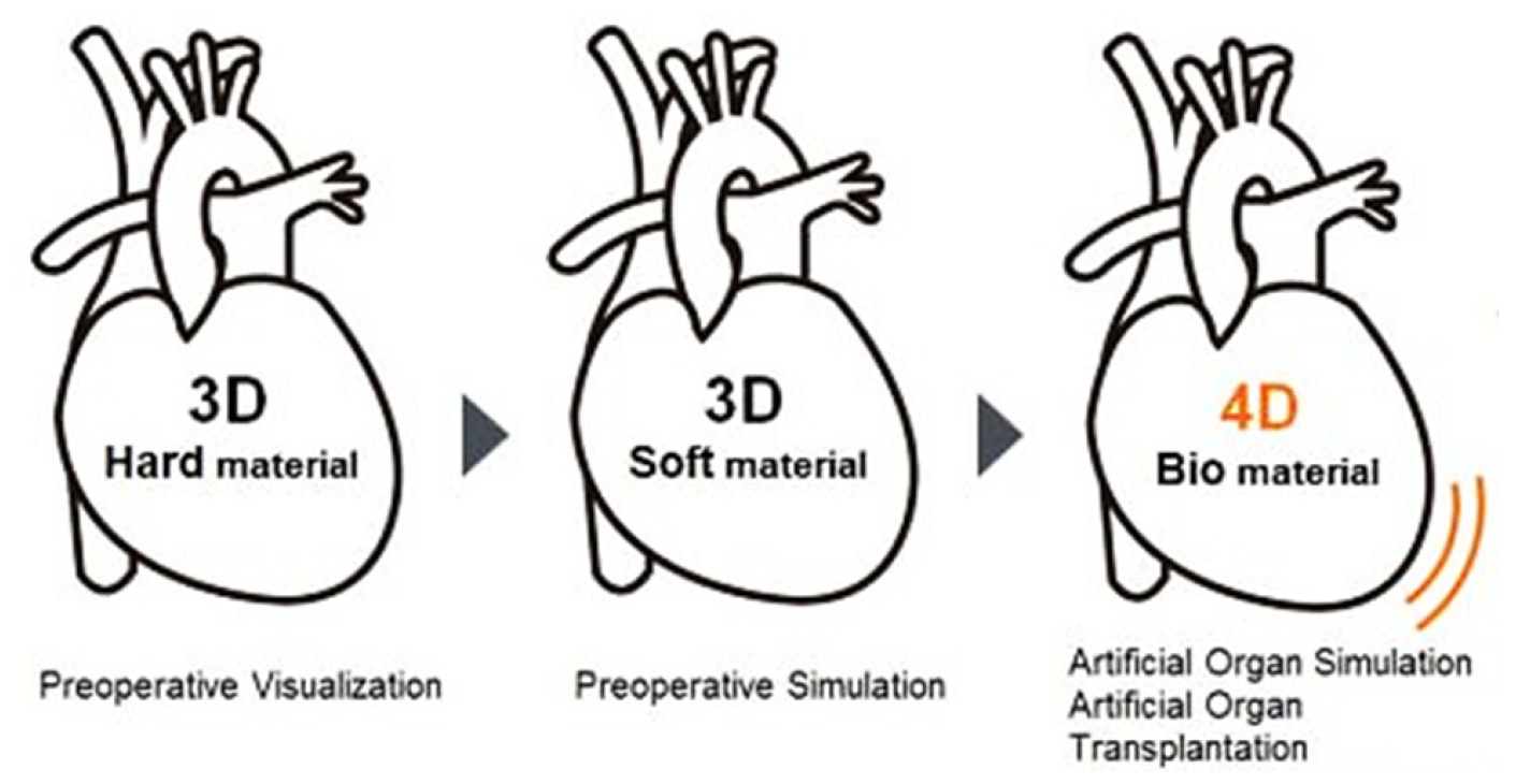
5. Future Trends
6. Conclusions
Author Contributions
Funding
Conflicts of Interest
References
- History of Additive Manufacturing. Available online: http://www.wohlersassociates.com/history2014.pdf/ (accessed on 6 February 2020).
- The Free Beginner’s Guide to 3D Printing. Available online: https://3dprintingindustry.com/3d-printing-basics-free-beginners-guide/ (accessed on 6 February 2020).
- History of EOS Company. Available online: https://www.eos.info/about_eos/history/ (accessed on 6 February 2020).
- The Complete History of 3D Printing: From 1980 to the Present Day. Available online: https://3dsourced.com/guides/history-of-3d-printing/ (accessed on 6 February 2020).
- Barron, J.; Wu, P.; Ladouceur, H.; Ringeisen, B. Biological Laser Printing: A Novel Technique for Creating Heterogeneous 3-dimensional Cell Patterns. Biomed. Microdevices 2004, 6, 139–147. [Google Scholar] [CrossRef] [PubMed]
- Derby, B. Printing and Prototyping of Tissues and Scaffolds. Science 2012, 338, 921–926. [Google Scholar] [CrossRef]
- Jang, E.H.; Kim, J.-H.; Lee, J.H.; Kim, D.-H.; Youn, Y.-N. Enhanced Biocompatibility of Multi-Layered, 3D Bio-Printed Artificial Vessels Composed of Autologous Mesenchymal Stem Cells. Polymers 2020, 12, 538. [Google Scholar] [CrossRef] [PubMed]
- Chia, H.; Wu, B. Recent advances in 3D printing of biomaterials. J. Biol. Eng. 2015, 9, 1–14. [Google Scholar] [CrossRef] [PubMed]
- ASTM International. ISO/ASTM 52900:2015 Additive Manufacturing—General Principles—Terminology; ASTM: West Conshohocken, PA, USA, 2015; p. 5. [Google Scholar]
- Fiedor, P.; Pilch, M.; Szymaszek, P.; Chachaj-Brekiesz, A.; Galek, M.; Ortyl, J. Photochemical Study of a New Bimolecular Photoinitiating System for Vat Photopolymerization 3D Printing Techniques under Visible Light. Catalysts 2020, 10, 284. [Google Scholar] [CrossRef]
- Crivello, J.; Reichmanis, E. Photopolymer Materials and Processes for Advanced Technologies. Chem. Mater. 2013, 26, 533–548. [Google Scholar] [CrossRef]
- Phillips, R. Photopolymerization. J. Photochem. 1984, 25, 79–82. [Google Scholar] [CrossRef]
- A Primer on UV-Curable Inkjet Inks. Available online: http://www.signindustry.com/flatbed_UV/articles/2008-11-17-SGIA_Primer_on_UV-Curable_Inkjet_Inks.php3/ (accessed on 6 February 2020).
- Ravve, A. Light-Associated Reactions of Synthetic Polymers; Springer: New York, NY, USA, 2006; ISBN 9780387318035. [Google Scholar]
- Desimone, J.; Alexander, M.; Nikita, E.; Edward, E.; Smulski, T. Continous Liquid Interphase Printing. U.S. Patent PCT/US2014/015506, 21 August 2014. [Google Scholar]
- Tumbleston, J.R.; Shirvanyants, D.; Ermoshkin, N.; Janusziewicz, R.; Johnson, A.R.; Kelly, D.; DeSimone, J.M. Continuous liquid interface production of 3D objects. Science 2015, 347, 1349–1352. [Google Scholar] [CrossRef]
- Huang, B.H.R.; Xue, Z.; Zhao, J.; Li, Q.; Xia, T.; Zhang, W.; Lu, C. Continuous liquid interface production of alginate/polyacrylamide hydrogels with supramolecular shape memory properties. Carbohydr. Polym. 2020, 231, 115736. [Google Scholar] [CrossRef]
- Redwood, B.; Schoöffer, F.; Garet, B. The 3D Printing Handbook: Technologies, Design and Applications; 3D Hubs: Amsterdam, The Netherlands, 2017; ISBN 9789082748505. [Google Scholar]
- Bártolo, P. Stereolithography: Materials, Processes and Applications; Springer: New York, NY, USA, 2011; ISBN 978-0-387-92903-3. [Google Scholar]
- Janusziewicz, R.; Tumbleston, J.R.; Quintanilla, A.L.; Mecham, S.J.; DeSimone, J.M. Layerless fabrication with continuous liquid interface production. Proc. Natl. Acad. Sci. USA 2016, 113, 11703–11708. [Google Scholar] [CrossRef] [PubMed]
- Stereolithography, SLA. Available online: https://www.manufacturingguide.com/en/stereolithography-sla (accessed on 22 July 2020).
- Lemma, E.; Spagnolo, B.; De Vittorio, M.; Pisanello, F. Studying Cell Mechanobiology in 3D: The Two-Photon Lithography Approach. Trends Biotechnol. 2019, 37, 358–372. [Google Scholar] [CrossRef]
- Bass, M. Handbook of Optics: Fundamentals, Techniques, and Design; McGraw-Hill Professional: New York, NY, USA, 1994. [Google Scholar]
- SLA vs. DLP: Guide to Resin 3D Printers. Available online: https://formlabs.com/blog/resin-3d-printer-comparison-sla-vs-dlp/ (accessed on 22 July 2020).
- Zhou, X.; Hou, Y.; Lin, J. A review on the processing accuracy of two-photon polymerization. AIP Adv. 2015, 5, 030701. [Google Scholar] [CrossRef]
- Ostendorf, A.; Chichkov, B.N. Two-photon polymerization: A new approach to micromachining. Photon Spectra 2006, 40, 72. [Google Scholar]
- Using Draft Resin. Available online: https://support.formlabs.com/s/article/Using-Draft-Resin?language=en_US// (accessed on 23 July 2020).
- Standard. Available online: https://formlabs-media.formlabs.com/datasheets/Clear_Resin_Technical.pdf/ (accessed on 23 July 2020).
- Draft Resin. Available online: https://formlabs-media.formlabs.com/datasheets/Draft_DataSheet_.pdf/ (accessed on 23 July 2020).
- Grey Pro. Available online: https://formlabs-media.formlabs.com/datasheets/Grey_Pro_Technical.pdf/ (accessed on 23 July 2020).
- Rigid. Available online: https://formlabs-media.formlabs.com/datasheets/Rigid_Technical.pdf/ (accessed on 23 July 2020).
- High Temp. Available online: https://formlabs-media.formlabs.com/datasheets/High_Temp_Technical.pdf/ (accessed on 23 July 2020).
- Durable. Available online: https://formlabs-media.formlabs.com/datasheets/1801084-TDS-ENUS-0P.pdf/ (accessed on 23 July 2020).
- Tough 1500. Available online: https://formlabs-media.formlabs.com/datasheets/Tough_1500_TDS_EN.pdf/ (accessed on 23 July 2020).
- Elastic. Available online: https://formlabs-media.formlabs.com/datasheets/Elastic_Resin_Technical.pdf/ (accessed on 23 July 2020).
- Flexible. Available online: https://formlabs-media.formlabs.com/datasheets/Flexible_Technical.pdf/ (accessed on 23 July 2020).
- Ceramic. Available online: https://formlabs-media.formlabs.com/datasheets/1907180-TDS-ENUS-0.pdf/ (accessed on 23 July 2020).
- Castable Wax. Available online: https://formlabs-media.formlabs.com/datasheets/Castable_Wax_Technical_Data_Sheet.pdf/ (accessed on 23 July 2020).
- How ROE Dental Lab Pivoted to Manufacturing Medical Supplies to Fight COVID-19. Available online: https://dental.formlabs.com/eu/blog/roe-dental-manufacturing-medical-supplies-swabs-covid-19/ (accessed on 23 July 2020).
- Biomodex. Available online: https://www.biomodex.com/ (accessed on 23 July 2020).
- Dental LT Clear. Available online: https://formlabs-media.formlabs.com/datasheets/Dental_LT_Clear_Technical.pdf/ (accessed on 23 July 2020).
- Dental SG. Available online: https://formlabs-media.formlabs.com/datasheets/DentalSG-DataSheet.pdf/ (accessed on 23 July 2020).
- Surgical Guide. Available online: https://formlabs-media.formlabs.com/datasheets/surgical_guide_technical_data_sheet_en.pdf/ (accessed on 23 July 2020).
- Gopinathan, J.; Noh, I. Recent trends in bioinks for 3D printing. Biomater. Res. 2018, 22, 11. [Google Scholar] [CrossRef]
- A Guide to Matrix Bioinks. Available online: https://www.allevi3d.com/a-guide-to-matrix-bioinks/ (accessed on 23 July 2020).
- Farsari, M.; Chichkov, B. Two-photon fabrication. Nat. Photon. 2009, 3, 450–452. [Google Scholar] [CrossRef]
- Rideell Partners with Carbon to Produce First-Ever 3D Printed Football Helmet Liner. Available online: https://www.carbon3d.com/news/riddell-partners-with-carbon-to-produce-next-gen-football-helmet/ (accessed on 6 February 2020).
- 8sole. Available online: https://www.8sole.com/ (accessed on 6 February 2020).
- Derek Luther: Zahájil jsem evoluci aditivní výroby v Adidasu. Available online: https://www.konstrukter.cz/derek-luther-zahajil-jsem-evoluci-aditivni-vyroby-v-adidasu/ (accessed on 6 February 2020).
- Using 3D Scanning and Printing to Help Children with Ear Deformities. Available online: https://www.artec3d.com/cases/prosthetic-3d-printed-ear-implants/ (accessed on 6 February 2020).
- Sonova’s Custom Hearing Aids are Discreet and Efficiently Made. Available online: https://www.trendhunter.com/trends/3d-printed-hearing-aids/ (accessed on 6 February 2020).
- Nasopharyngeal Swabs. Available online: https://www.carbon3d.com/covid19/ (accessed on 6 December 2020).
- New Light-Touch Supports for Castable Wax Resin in PreForm 3.4.6. Available online: https://formlabs.com/eu/blog/easier-post-processing-jewelry-3d-prints/ (accessed on 23 July 2020).
- Hsieh, T.; Ng, C.B.; Narayanan, K.; Wan, A.; Ying, J. Three-dimensional microstructured tissue scaffolds fabricated by two-photon laser scanning photolithography. Biomaterials 2010, 31, 7648–7652. [Google Scholar] [CrossRef] [PubMed]
- Suzuki, M.; Takahashi, T.; Aoyagi, S. 3D laser lithographic fabrication of hollow microneedle mimicking mosquitos and its characterization. Int. J. Nanotechnol. 2018, 15, 157–173. [Google Scholar] [CrossRef]
- Göring, G.; Dietrich, P.I.; Blaicher, M.; Sharma, S.; Korvink, J.G.; Schimmel, T.; Koos, C.; Hölscher, H. Tailored probes for atomic force microscopy fabricated by two-photon polymerization. Appl. Phys. Lett. 2016, 109, 063101. [Google Scholar] [CrossRef]
- Zhou, L.; Gao, Q.; Fu, J.; Chen, Q.; Zhu, J.; Sun, Y.; He, Y. Multimaterial 3D Printing of Highly Stretchable Silicone Elastomers. ACS Appl. Mater. Interfaces 2019, 11, 23573–23583. [Google Scholar] [CrossRef]
- Valentine, A.; Busbee, T.; Boley, J.; Raney, J.; Chortos, A.; Kotikian, A.; Berrigan, J.; Durstock, M.; Lewis, J. Hybrid 3D Printing of Soft Electronics. Adv. Mater. 2017, 29, 1703817. [Google Scholar] [CrossRef] [PubMed]
- Truby, R.; Lewis, J. Printing soft matter in three dimensions. Nature 2016, 540, 371–378. [Google Scholar] [CrossRef]
- Tawk, C.; in het Panhuis, M.; Spinks, G.; Alici, G. Bioinspired 3D Printable Soft Vacuum Actuators for Locomotion Robots, Grippers and Artificial Muscles. Soft Robot. 2018, 5, 685–694. [Google Scholar] [CrossRef]
- Duoss, E.; Weisgraber, T.; Hearon, K.; Zhu, C.; Small, W.; Metz, T.; Vericella, J.; Barth, H.; Kuntz, J.; Maxwell, R.; et al. Three-Dimensional Printing of Elastomeric, Cellular Architectures with Negative Stiffness. Adv. Funct. Mater. 2014, 24, 4905–4913. [Google Scholar] [CrossRef]
- Bagheri, A.; Jin, J. Photopolymerization in 3D Printing. ACS Appl. Polym. Mater. 2019, 1, 593–611. [Google Scholar] [CrossRef]
- Graeber, G.; Martin Kieliger, O.; Schutzius, T.; Poulikakos, D. 3D-Printed Surface Architecture Enhancing Superhydrophobicity and Viscous Droplet Repellency. ACS Appl. Mater. Interfaces 2018, 10, 43275–43281. [Google Scholar] [CrossRef] [PubMed]
- Gupta, T.; Strelcov, E.; Holland, G.; Schumacher, J.; Yang, Y.; Esch, M.; Aksyuk, V.; Zeller, P.; Amati, M.; Gregoratti, L.; et al. Electron and X-ray Focused Beam-Induced Cross-Linking in Liquids: Toward Rapid Continuous 3D Nanoprinting and Interfacing using Soft Materials. ACS Nano 2020, 14, 12982–12992. [Google Scholar] [CrossRef] [PubMed]
- Cui, H.; Zhu, W.; Holmes, B.; Zhang, L. Biologically Inspired Smart Release System Based on 3D Bioprinted Perfused Scaffold for Vascularized Tissue Regeneration. Adv. Sci. 2016, 3, 1600058. [Google Scholar] [CrossRef] [PubMed]
- Clausen, A.; Wang, F.; Jensen, J.; Sigmund, O.; Lewis, J. Topology Optimized Architectures with Programmable Poisson’s Ratio over Large Deformations. Adv. Mater. 2015, 27, 5523–5527. [Google Scholar] [CrossRef]
- López-Valdeolivas, M.; Liu, D.; Broer, D.; Sánchez-Somolinos, C. 4D Printed Actuators with Soft-Robotic Functions. Macromol. Rapid Commun. 2018, 39, 1700710. [Google Scholar] [CrossRef] [PubMed]
- Zarek, M.; Layani, M.; Cooperstein, I.; Sachyani, E.; Cohn, D.; Magdassi, S. 3D Printing of Shape Memory Polymers for Flexible Electronic Devices. Adv. Mater. 2016, 28, 4449–4454. [Google Scholar] [CrossRef] [PubMed]
- Kelly, B.; Bhattacharya, I.; Heidari, H.; Shusteff, M.; Spadaccini, C.; Taylor, H. Volumetric additive manufacturing via tomographic reconstruction. Science 2019, 363, 1075–1079. [Google Scholar] [CrossRef] [PubMed]
- Chen, M.; Lee, H.; Yang, J.; Xu, Z.; Huang, N.; Chan, B.; Kim, J. Parallel, Multi-Material Electrohydrodynamic 3D Nanoprinting. Small 2020, 16, 1906402. [Google Scholar] [CrossRef] [PubMed]
- Kiefer, P.; Hahn, V.; Nardi, M.; Yang, L.; Blasco, E.; Barner-Kowollik, C.; Wegener, M. Sensitive Photoresists for Rapid Multiphoton 3D Laser Micro- and Nanoprinting. Adv. Opt. Mater. 2020, 8, 2000895. [Google Scholar] [CrossRef]
- Loterie, D.; Delrot, P.; Moser, C. High-resolution tomographic volumetric additive manufacturing. Nat. Commun. 2020, 11, 1–6. [Google Scholar] [CrossRef]
- Robotics, Sensors, & Devices. Available online: https://www.sri.com/robotics-sensors-devices/ (accessed on 12 February 2021).
- Tijing, L.; Dizon, J.; Ibrahim, I.; Nisay, A.; Shon, H.; Advincula, R. 3D printing for membrane separation, desalination and water treatment. Appl. Mater. Today 2020, 18, 100486. [Google Scholar] [CrossRef]
- Kuang, X.; Roach, D.; Wu, J.; Hamel, C.; Ding, Z.; Wang, T.; Dunn, M.; Qi, H. Advances in 4D Printing: Materials and Applications. Adv. Funct. Mater. 2018, 29, 1805290. [Google Scholar] [CrossRef]
- On the Road to 3D Printed Organs. Available online: https://www.the-scientist.com/news-opinion/on-the-road-to-3-d-printed-organs-67187/ (accessed on 6 December 2020).
- Wu, Y.; Heikal, L.; Ferns, G.; Ghezzi, P.; Nokhodchi, A.; Maniruzzaman, M. 3D Bioprinting of Novel Biocompatible Scaffolds for Endothelial Cell Repair. Polymers 2019, 11, 1924. [Google Scholar] [CrossRef] [PubMed]
- Hospodiuk, M.; Dey, M.; Sosnoski, D.; Ozbolat, I.T. The bioink: A comprehensive review on bioprintable materials. Biotechnol. Adv. 2017, 35, 217–239. [Google Scholar] [CrossRef] [PubMed]
- Mironov, V.; Boland, T.; Trusk, T.; Forgacs, G.; Markwald, R.R. Organ printing: Computer-aided jet-based 3D tissue engineering. Trends Biotechnol. 2003, 21, 157–161. [Google Scholar] [CrossRef]
- Kunimoto, K. Turn to the Future for Living Body Medical Design. In Proceedings of the Simulation Community Conference “Science in the Age of Experience” 2017, Chicago, IL, USA, 15–18 May 2017. [Google Scholar]


| Properties | Standard | ||||
|---|---|---|---|---|---|
| Standard (Grayscale, Clear, Colors) | Draft Resin | ||||
| Green 1 | Postcured 2 | Green 3 | Postcured at Room Temperature 4 | Postcured at 60 °C 5 | |
| Tensile Properties | |||||
| Ultimate Tensile Strength | 38 MPa | 65 MPa | 23 MPa | 28 MPa | 36 MPa |
| Tensile Modulus | 1.6 GPa | 2.8 GPa | 0.9 GPa | 1.3 GPa | 1.6 GPa |
| Elongation at Failure | 12% | 6.2% | 17% | 10% | 7% |
| Flexural Properties | |||||
| Flexural Modulus | 1.25 GPa | 2.2 GPa | 0.6 GPa | 0.9 GPa | 1.5 GPa |
| Flexural Stress at Break | - | - | - | - | - |
| Impact Properties | |||||
| Notched Izod | 16 J/m | 25 J/m | 35 J/m | 35 J/m | 21 J/m |
| Temperature Properties | |||||
| Heat Deflection Temp. @ 264 psi | 42.7 °C | 58.4 °C | 43.3 °C | 44.3 °C | 50.1 °C |
| Heat Deflection Temp. @ 66 psi | 49.7 °C | 73.1 °C | 50.6 °C | 50.7 °C | 63.4 °C |
| Properties * | Grey Pro | Rigid | High Temp | ||||
|---|---|---|---|---|---|---|---|
| Green 1 | Postcured 2 | Green 3 | Postcured 4 | Green 5 | Post-Cured 6 | Post-Cured + Thermally Postcured 7 | |
| Tensile Properties | |||||||
| Ultimate Tensile Strength | 35 MPa | 61 MPa | 40 MPa | 75 MPa | 20.9 MPa | 58.3 MPa | 51.1 MPa |
| Young’s Modulus | - | - | - | - | - | - | - |
| Tensile Modulus | 1.4 GPa | 2.6 GPa | 2.2 GPa | 4.1 GPa | 0.75 GPa | 2.75 GPa | 2.9 GPa |
| Elongation | 32.5% | 13% | 13.3% | 5.6% | - | - | - |
| Elongation at Break | - | - | - | - | 14% | 3.3% | 2.4% |
| Flexural Properties | |||||||
| Flexural Modulus | 0.94 GPa | 2.2 GPa | 1.37 GPa | 3.7 GPa | 0.69 GPa | 2.62 GPa | 2.62 GPa |
| Flexural Stress at 5% Strain | 39 MPa | 86 MPa | 49 MPa | 121 MPa | - | - | - |
| Flexural Strength at Break | - | - | - | - | 24.1 MPa | 94.5 MPa | 93.8 MPa |
| Impact Properties | |||||||
| Notched IZOD | - | 18.7 J/m | - | 18.8 J/m | 32.8 J/m | 18.2 J/m | 24.2 J/m |
| Temperature Properties | |||||||
| Head Deflection Temp. @ 1.8 MPa | - | 62.4 °C | - | 74 °C | 43.6 °C | 99.2 °C | 101 °C |
| Heat Deflection Temp. @ 0.45 MPa | - | 77.5 °C | - | 88 °C | 49.3 °C | 142 °C | 238 °C |
| Thermal Expansion (−30 to 30 °C) | - | 78.5 µm/m/°C | - | 53 µm/m/°C | - | - | - |
| Thermal Expansion (0 to 150 °C) | - | - | - | - | 118.1 µm/m/°C | 79.6 µm/m/°C | 74 µm/m/°C |
| Properties | Durable | Tough | ||
|---|---|---|---|---|
| Green 1 | Postcured 2 | Green 1 | Postcured 3 | |
| Tensile Properties | ||||
| Ultimate Tensile Strength | 13 MPa | 28 MPa | 26 MPa | 33 MPa |
| Young’s Modulus | - | - | - | - |
| Tensile Modulus | 0.24 GPa | 1 GPa | 0.94 GPa | 1.5 GPa |
| Elongation at Failure | 75% | 55% | 69% | 51% |
| Flexural Properties | ||||
| Flexural Modulus | 0.04 MPa | 0.66 GPa | 0.44 GPa | 1.4 GPa |
| Flexural Strength | - | - | 15 MPa | 39 MPa |
| Flexural Stress at 5% Strain | 1.0 MPa | 24 MPa | - | - |
| Impact Properties | ||||
| Notched IZOD | 127 J/m | 114 J/m | 72 J/m | 67 J/m |
| Unnotched IZOD | - | - | 902 J/m | 1387 J/m |
| Thermal Properties | ||||
| Heat Deflection Temp. @ 1.8 MPa | - | - | 34 °C | 45 °C |
| Heat Deflection Temp. @ 0.45 MPa | <30 °C | 41 °C | 42 °C | 52 °C |
| Thermal Expansion | 124 µm/m/°C | 106 µm/m/°C | 114 µm/m/°C | 97 µm/m/°C |
| Properties | Elastic | Flexible | |||
|---|---|---|---|---|---|
| Green 1 | Postcured 2 | Green 1 | Postcured 3 | ||
| Tensile Properties | |||||
| Ultimate Tensile Strength | 1.61 MPa 4 | 3.23 MPa 4 | 3.3–3.4 MPa 4 | - | |
| Elongation at Failure | 100% | 100% | 60% | 75–85% | |
| Stress at 50% Elongation | 0.92 MPa | 0.94 MPa | - | - | |
| Stress at 100% Elongation | 1.54 MPa | 1.59 MPa | - | - | |
| Other Properties | |||||
| Hardness Shore | 40 A | 50 A | 70–75 A | 80–85 A | |
| Vicat Softening Point | - | - | 231 °C | 230 °C | |
| Properties | Ceramic | Castable Wax | ||
|---|---|---|---|---|
| Green 1 | Fired 2 | |||
| Tensile Properties | ||||
| Ultimate Tensile Strength | 5.1 MPa | - | 11.6 MPa | |
| Young’s Modulus | - | - | 220 MPa | |
| Tensile Modulus | 1.03 GPa | 50 GPa | - | |
| Elongation at Failure | 1.4% | - | 13% | |
| Flexural Properties | ||||
| Flexural Modulus | 994.6 MPa | - | - | |
| Flexural Stress at Break | 10.27 MPa | 33.5 MPa | - | |
| Impact Properties | ||||
| Notched IZOD | 18.42 J/m | - | - | |
| Temperature Properties | ||||
| Heat Deflection Temp. @ 264 psi | 74.7 °C | - | - | |
| Heat Deflection Temp. @ 66 psi | >290 °C | - | - | |
| Other Properties | ||||
| Cold Crushing Strength | - | 72.2 MPa | - | |
| Shear Modulus | - | 21.9 GPa | - | |
| Poisson’s Ratio | - | 0.140 | - | |
| Density | - | 1.9 g/cm3 | - | |
| Properties | Medical | ||
|---|---|---|---|
| Dental LT Clear | Dental SG | Surgical Guide Resin | |
| Ultimate Tensile Strength | - | >50 MPa | 73 MPa |
| Young’s Modulus | - | - | 2.9 GPa |
| Elongation at Failure | - | - | 12.3% |
| Flexural Modulus | >1300 MPa | >1500 MPa | 2500 MPa |
| Flexural Stress at Break | - | - | 103 MPa |
| Hardness Shore | 80–90 D | >80 D | 67 D |
| Scale | Application | Material | Machine | Technology | Note | Ref. |
|---|---|---|---|---|---|---|
| cm | Football helmet liner | Polyurethane elastomer (EPU40) | Carbon M2 | CDLP | Helmet liner constructed with 140,000 interconnected struts for impact attenuating purpose. | [47] |
| cm | Shoe soles (orthotics/aesthetics) | Polyurethane elastomer (EPU40) | Carbon M2 | -/Digital Light Synthesis (DLS) | Customized shoe soles for orthotics/shoe soles from lattice structures for optimal usage and aesthetics. | [48,49] |
| mm | Artificial ears | - | Roland ARM-10 | Stereolithography | Ear reconstruction based on 3D scans from patients. | [50] |
| mm | Hearing aids | Light-cured acrylic resin | - | - | Customized hearing aid shells from 3D scanned ear canals. | [51] |
| mm | Sampling swabs | Surgical Guide Resin | FormLabs Form 3/Carbon M2 | CDLP | Sampling swabs with plastic heads for collecting efficiency and comfort. | [52] |
| mm | Jewelry | Castable wax resin | Form 3, Form 3L | Low force stereolithography (LFS) | Detailed jewelry designs are 3D-printed for investment casting. | [53] |
| mm | Scaffolds for cells | Accura SI10 | Scanlabs | 2PL | Scaffolds work as living cell encapsulators. | [54] |
| µm | Microneedles | Photopolymer | Nanoscribe GT | 2PL | Mosquito-liked microneedles. | [55] |
| µm | Probes for atomic force microcopy | Resist (IP-Dip) | Photonic Professional GT | 2PL | Printing tips can be carbonized by utilizing a pyrolysis process. | [56] |
| mm/µm | Flexible electronics | Silicon elastomers with nanosilica/ Conductive and dielectric elastomeric materials | - | - | Soft sensors, actuators, and robots to improve human–machine interactions. Strain sensors embedded into a glove shape. | [57,58,59,60,61] |
| mm/µm | Smart composites | Viscoelastic inks | - | - | Porous, elastomeric architectures with a programmable Poisson ratio and mechanical properties utilizing the ordered arrangement of sub-millimeter struts. | [57,58] |
| mm/µm | Superhydrophobic objects | Inks | - | DLP | Objects with special surface structures that are utilized for self-cleaning, drag reduction, increased buoyancy, and air-conditioning applications. | [62,63,64] |
| mm/µm | Living tissue structures | Bioinks | - | - | Small-scale, simplified liver, kidney, or lung tissue, mimicking their natural counterparts. | [65,66] |
| mm/µm | 4D-printed actuators | Liquid crystalline polymers (LCPs) | - | - | Stimuli-responsive liquid crystalline elastomeric structures. The printing process prescribes a reversible shape-morphing behavior, offering a new paradigm for active polymer system preparation. | [67,68] |
| µm | Tomographic 3D printing (fabrication of advanced and functional constructs) | Photopolymer | - | DLP | Object is simultaneously solidified by irradiating a liquid photopolymer volume from multiple angles with dynamic light patterns. | [69,70] |
| nm | 3D nanoprinting | Photopolymer | - | Electron/X-ray lithography | Multiphoton polymer cross-linking evolves as the core process behind high-resolution additive microfabrication with soft materials for implantable/wearable electronics, tissue engineering, microrobotics, biosensing, drug delivery, etc. | [71,72,73] |
Publisher’s Note: MDPI stays neutral with regard to jurisdictional claims in published maps and institutional affiliations. |
© 2021 by the authors. Licensee MDPI, Basel, Switzerland. This article is an open access article distributed under the terms and conditions of the Creative Commons Attribution (CC BY) license (http://creativecommons.org/licenses/by/4.0/).
Share and Cite
Pagac, M.; Hajnys, J.; Ma, Q.-P.; Jancar, L.; Jansa, J.; Stefek, P.; Mesicek, J. A Review of Vat Photopolymerization Technology: Materials, Applications, Challenges, and Future Trends of 3D Printing. Polymers 2021, 13, 598. https://doi.org/10.3390/polym13040598
Pagac M, Hajnys J, Ma Q-P, Jancar L, Jansa J, Stefek P, Mesicek J. A Review of Vat Photopolymerization Technology: Materials, Applications, Challenges, and Future Trends of 3D Printing. Polymers. 2021; 13(4):598. https://doi.org/10.3390/polym13040598
Chicago/Turabian StylePagac, Marek, Jiri Hajnys, Quoc-Phu Ma, Lukas Jancar, Jan Jansa, Petr Stefek, and Jakub Mesicek. 2021. "A Review of Vat Photopolymerization Technology: Materials, Applications, Challenges, and Future Trends of 3D Printing" Polymers 13, no. 4: 598. https://doi.org/10.3390/polym13040598
APA StylePagac, M., Hajnys, J., Ma, Q.-P., Jancar, L., Jansa, J., Stefek, P., & Mesicek, J. (2021). A Review of Vat Photopolymerization Technology: Materials, Applications, Challenges, and Future Trends of 3D Printing. Polymers, 13(4), 598. https://doi.org/10.3390/polym13040598