
Dielectric Elastomer Fiber Actuators with Aqueous Electrode


Abstract
:
1. Introduction
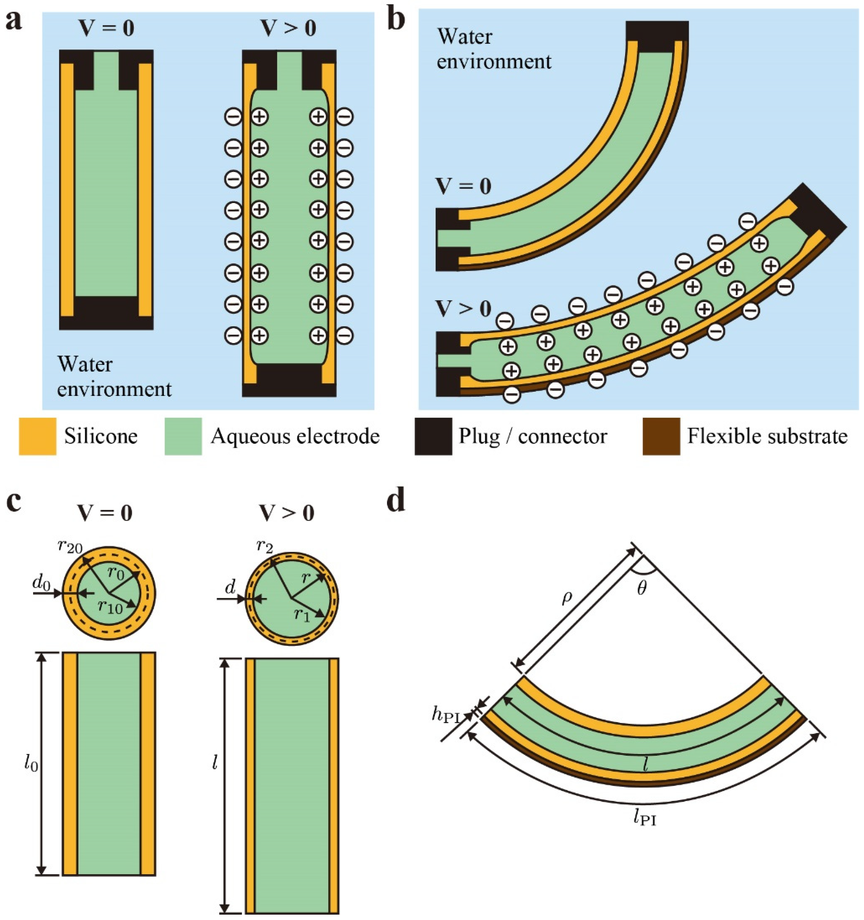
2. Actuator Model
3. Materials and Methods
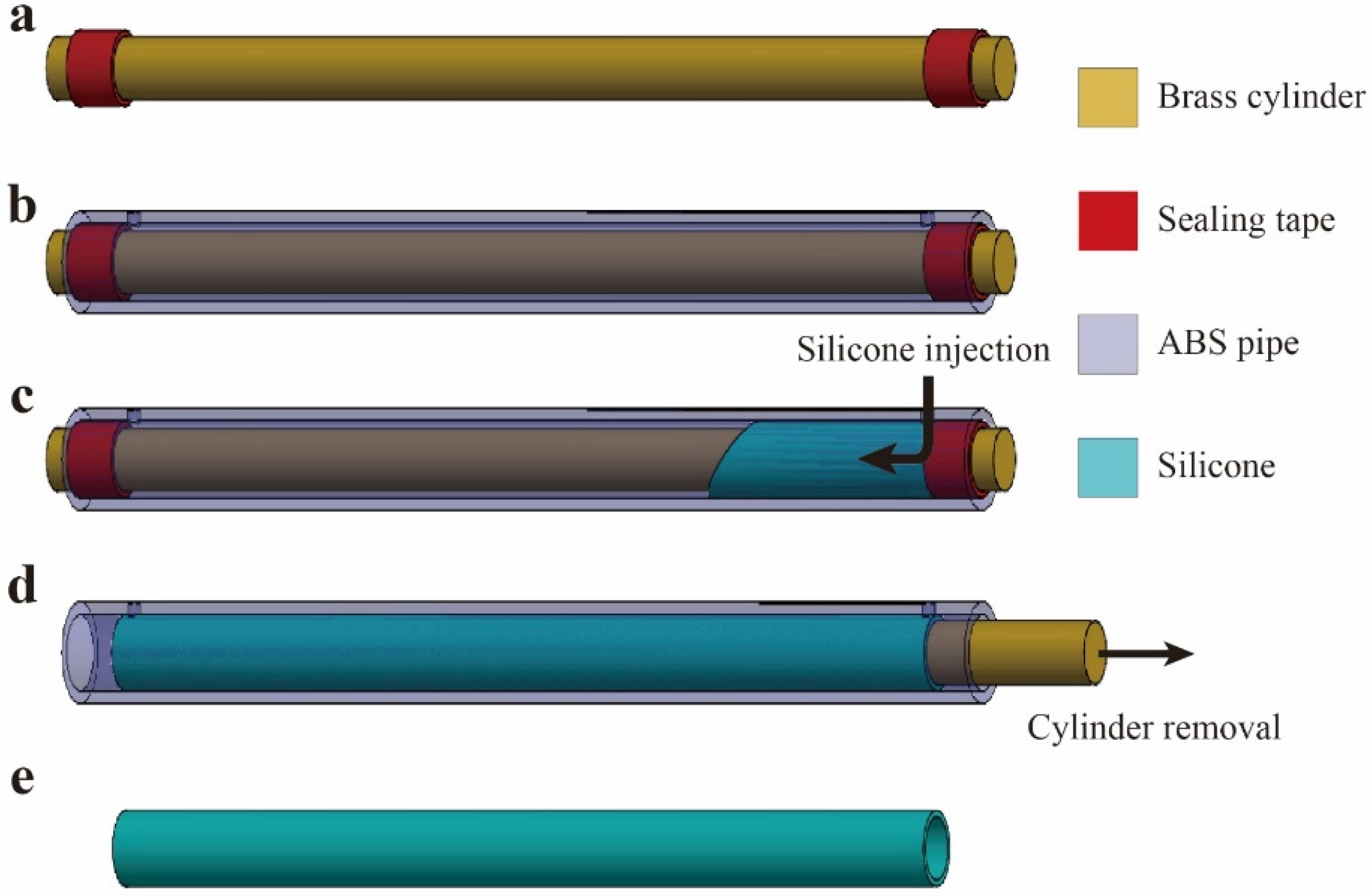
3.1. Fabrication of Silicone Tube
3.2. Fabrication of DEFAs
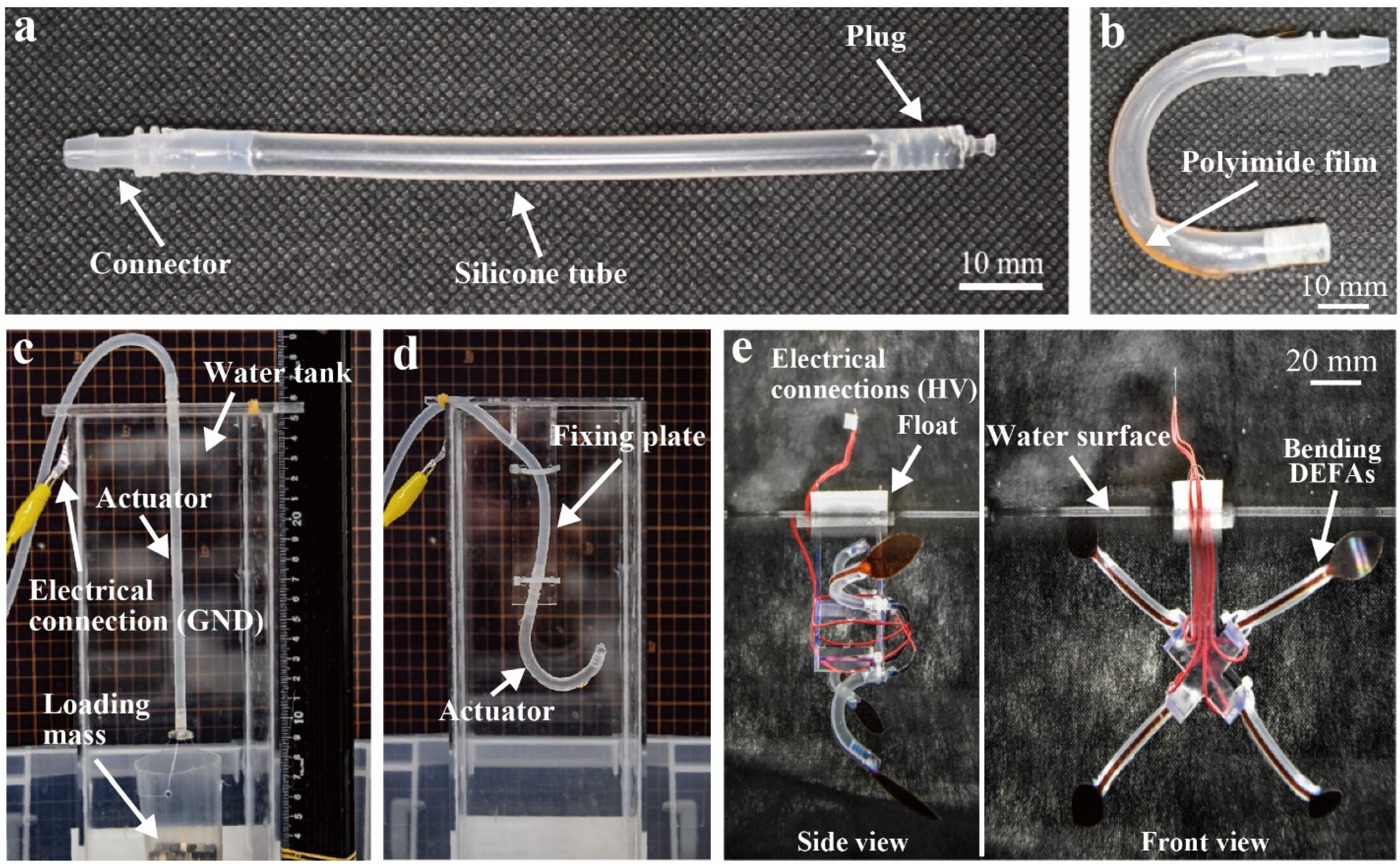
3.3. Characterization of DEFAs
3.4. Fabrication and Testing of Jellyfish-Type Underwater Robot
4. Results and Discussion
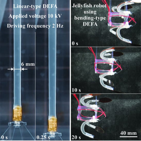
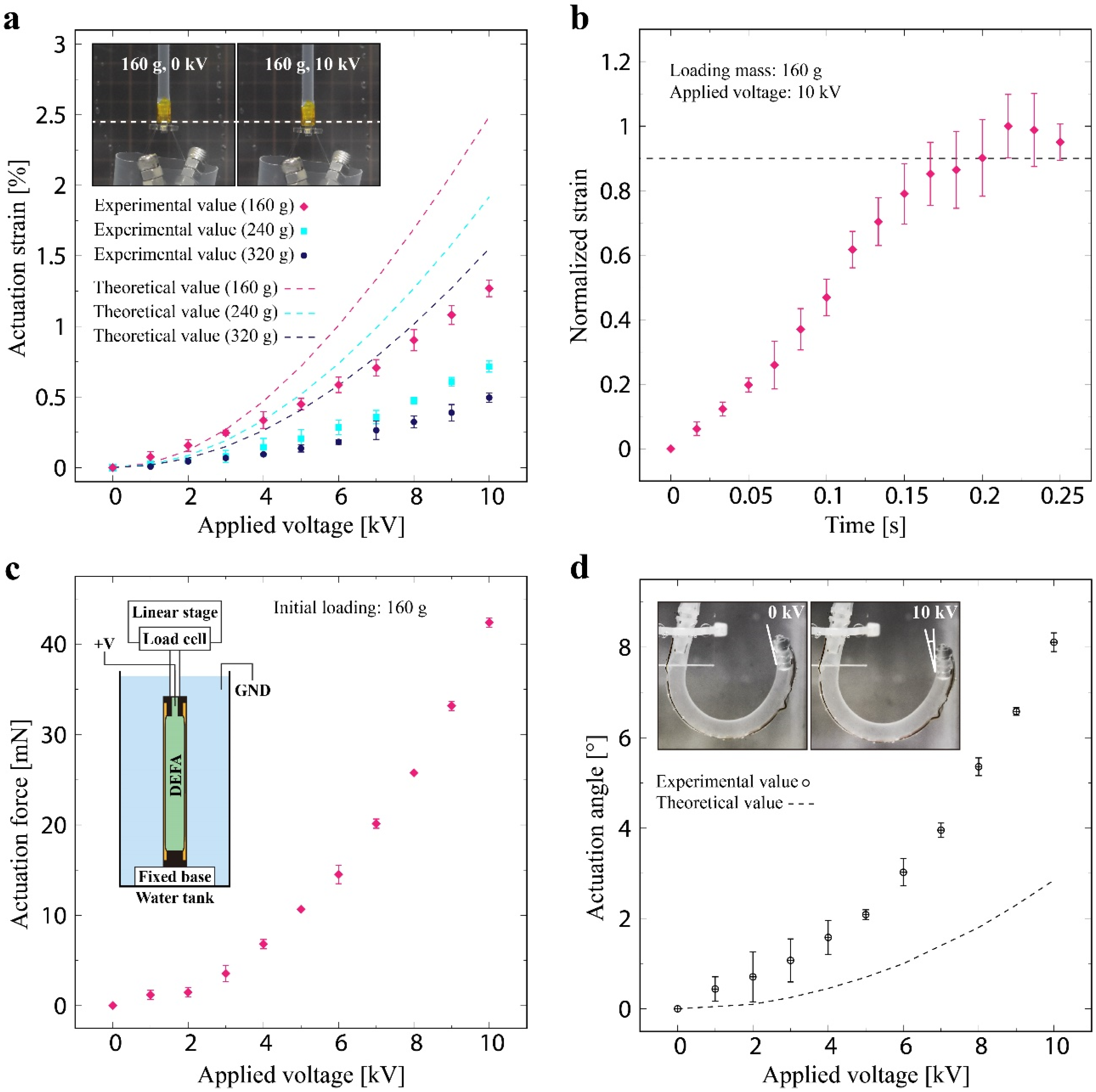
4.1. DEFAs
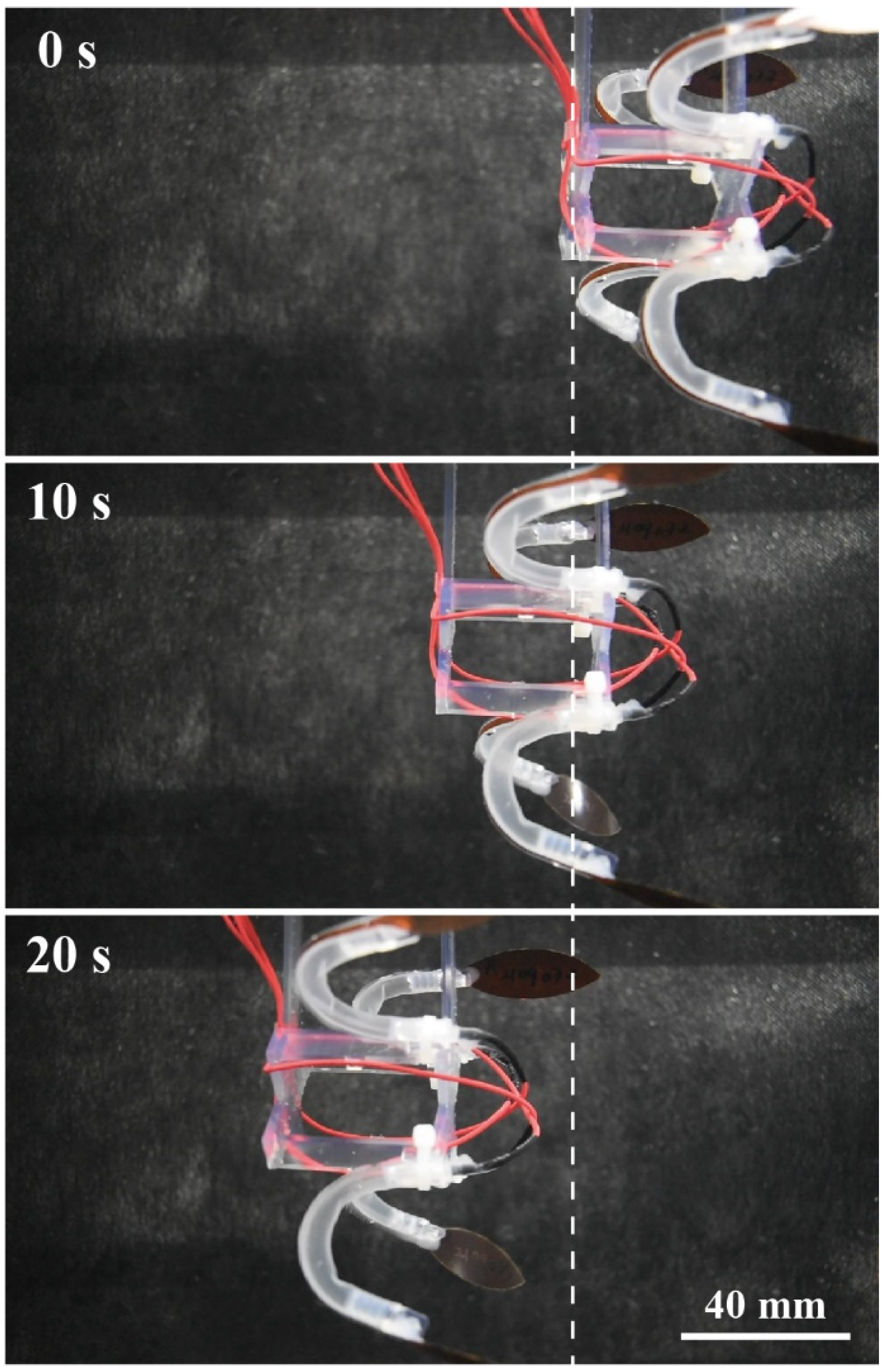
4.2. Jellyfish-Type Underwater Robot
5. Conclusions
Supplementary Materials
Author Contributions
Funding
Institutional Review Board Statement
Informed Consent Statement
Data Availability Statement
Acknowledgments
Conflicts of Interest
References
- Rus, D.; Tolley, M.T. Design, fabrication and control of soft robots. Nature 2015, 521, 467–475. [Google Scholar] [CrossRef] [PubMed] [Green Version]
- Rich, S.I.; Wood, R.J.; Majidi, C. Untethered soft robotics. Nat. Electron. 2018, 1, 102–112. [Google Scholar] [CrossRef]
- Shintake, J.; Cacucciolo, V.; Floreano, D.; Shea, H. Soft robotic grippers. Adv. Mater. 2018, 30, 1707035. [Google Scholar] [CrossRef] [PubMed] [Green Version]
- Guo, Y.; Liu, L.; Liu, Y.; Leng, J. Review of dielectric elastomer actuators and their applications in soft robots. Adv. Intell. Syst. 2021, 3, 2000282. [Google Scholar] [CrossRef]
- Gupta, U.; Qin, L.; Wang, Y.; Godaba, H.; Zhu, J. Soft robots based on dielectric elastomer actuators: A review. Smart Mater. Struct. 2019, 28, 103002. [Google Scholar] [CrossRef]
- Gu, G.-Y.; Zhu, J.; Zhu, L.-M.; Zhu, X. A survey on dielectric elastomer actuators for soft robots. Bioinspir. Biomim. 2017, 12, 011003. [Google Scholar] [CrossRef] [PubMed]
- Hajiesmaili, E.; Clarke, D.R. Dielectric elastomer actuators. J. Appl. Phys. 2021, 129, 151102. [Google Scholar] [CrossRef]
- Ji, X.; Liu, X.; Cacucciolo, V.; Imboden, M.; Civet, Y.; El Haitami, A.; Cantin, S.; Perriard, Y.; Shea, H. An autonomous untethered fast soft robotic insect driven by low-voltage dielectric elastomer actuators. Sci. Robot. 2019, 4, eaaz6451. [Google Scholar] [CrossRef] [PubMed]
- Brochu, P.; Pei, Q. Advances in dielectric elastomers for actuators and artificial muscles. Macromol. Rapid Commun. 2010, 31, 10–36. [Google Scholar] [CrossRef]
- Li, T.; Keplinger, C.; Baumgartner, R.; Bauer, S.; Yang, W.; Suo, Z. Giant voltage-induced deformation in dielectric elastomers near the verge of snap-through instability. J. Mech. Phys. Solids 2013, 61, 611–628. [Google Scholar] [CrossRef]
- Kovacs, G.; Lochmatter, P.; Wissler, M. An arm wrestling robot driven by dielectric elastomer actuators. Smart Mater. Struct. 2007, 16, S306–S317. [Google Scholar] [CrossRef]
- Kovacs, G.; Düring, L.; Michel, S.; Terrasi, G. Stacked dielectric elastomer actuator for tensile force transmission. Sens. Actuators A Phys. 2009, 155, 299–307. [Google Scholar] [CrossRef]
- Araromi, O.A.; Gavrilovich, I.; Shintake, J.; Rosset, S.; Richard, M.; Gass, V.; Shea, H.R. Rollable multisegment dielectric elastomer minimum energy structures for a deployable microsatellite gripper. IEEE/ASME Trans. Mechatron. 2015, 20, 438–446. [Google Scholar] [CrossRef]
- Gisby, T.A.; O’Brien, B.M.; Anderson, I.A. Self sensing feedback for dielectric elastomer actuators. Appl. Phys. Lett. 2013, 102, 193703. [Google Scholar] [CrossRef]
- Rosset, S.; O’Brien, B.M.; Gisby, T.; Xu, D.; Shea, H.R.; Anderson, I.A. Self-sensing dielectric elastomer actuators in closed-loop operation. Smart Mater. Struct. 2013, 22, 104018. [Google Scholar] [CrossRef] [Green Version]
- Xiong, J.; Chen, J.; Lee, P.S. Functional fibers and fabrics for soft robotics, wearables, and human–robot interface. Adv. Mater. 2021, 33, 2002640. [Google Scholar] [CrossRef]
- Kurumaya, S.; Suzumori, K.; Nabae, H.; Wakimoto, S. Musculoskeletal lower-limb robot driven by multifilament muscles. ROBOMECH J. 2016, 3, 18. [Google Scholar] [CrossRef] [Green Version]
- Kurumaya, S.; Nabae, H.; Endo, G.; Suzumori, K. Active textile braided in three strands with thin McKibben muscle. Soft Robot. 2019, 6, 250–262. [Google Scholar] [CrossRef] [PubMed]
- Thompson, N.; Zhang, X.; Ayala, F.; Hsiao-Wecksler, E.T.; Krishnan, G. Augmented joint stiffness and actuation using architectures of soft pneumatic actuators. In Proceedings of the 2018 IEEE International Conference on Robotics and Automation (ICRA), Brisbane, QLD, Australia, 21–25 May 2018; pp. 1533–1538. [Google Scholar]
- Sinatra, N.R.; Teeple, C.B.; Vogt, D.M.; Parker, K.K.; Gruber, D.F.; Wood, R.J. Ultragentle manipulation of delicate structures using a soft robotic gripper. Sci. Robot. 2019, 4, eaax5425. [Google Scholar] [CrossRef]
- Christianson, C.; Goldberg, N.N.; Deheyn, D.D.; Cai, S.; Tolley, M.T. Translucent soft robots driven by frameless fluid electrode dielectric elastomer actuators. Sci. Robot. 2018, 3, 1–9. [Google Scholar] [CrossRef] [Green Version]
- Li, T.; Li, G.; Liang, Y.; Cheng, T.; Dai, J.; Yang, X.; Liu, B.; Zeng, Z.; Huang, Z.; Luo, Y.; et al. Fast-moving soft electronic fish. Sci. Adv. 2017, 3, e1602045. [Google Scholar] [CrossRef] [Green Version]
- Arora, S.; Ghosh, T.; Muth, J. Dielectric elastomer based prototype fiber actuators. Sens. Actuators A Phys. 2007, 136, 321–328. [Google Scholar] [CrossRef]
- Kofod, G.; Stoyanov, H.; Gerhard, R. Multilayer coaxial fiber dielectric elastomers for actuation and sensing. Appl. Phys. A Mater. Sci. Process. 2011, 102, 577–581. [Google Scholar] [CrossRef]
- Kunze, J.; Prechtl, J.; Bruch, D.; Fasolt, B.; Nalbach, S.; Motzki, P.; Seelecke, S.; Rizzello, G. Design, manufacturing, and characterization of thin, core-free, rolled dielectric elastomer actuators. Actuators 2021, 10, 69. [Google Scholar] [CrossRef]
- Chortos, A.; Mao, J.; Mueller, J.; Hajiesmaili, E.; Lewis, J.A.; Clarke, D.R. Printing reconfigurable bundles of dielectric elastomer fibers. Adv. Funct. Mater. 2021, 31, 2010643. [Google Scholar] [CrossRef]
- Kofod, G.; Wirges, W.; Paajanen, M.; Bauer, S. Energy minimization for self-organized structure formation and actuation. Appl. Phys. Lett. 2007, 90, 081916. [Google Scholar] [CrossRef]
- Petralia, M.T.; Wood, R.J. Fabrication and analysis of dielectric-elastomer minimum-energy structures for highly-deformable soft robotic systems. In Proceedings of the 2010 IEEE/RSJ International Conference on Intelligent Robots and Systems, Taipei, Taiwan, 18–22 October 2010; pp. 2357–2363. [Google Scholar]
- Rosset, S.; Araromi, O.A.; Shintake, J.; Shea, H.R. Model and design of dielectric elastomer minimum energy structures. Smart Mater. Struct. 2014, 23, 085021. [Google Scholar] [CrossRef] [Green Version]
- Shintake, J.; Rosset, S.; Schubert, B.E.; Floreano, D.; Shea, H.R. A foldable antagonistic actuator. IEEE/ASME Trans. Mechatron. 2015, 20, 1997–2008. [Google Scholar] [CrossRef]
- Yeoh, O.H. Some forms of the strain energy function for rubber. Rubber Chem. Technol. 1993, 66, 754–771. [Google Scholar] [CrossRef]
- Schubert, B.E.; Floreano, D. Variable stiffness material based on rigid low-melting-point-alloy microstructures embedded in soft poly(dimethylsiloxane) (PDMS). RSC Adv. 2013, 3, 24671. [Google Scholar] [CrossRef] [Green Version]
- Vaicekauskaite, J.; Mazurek, P.; Vudayagiri, S.; Skov, A.L. Mapping the mechanical and electrical properties of commercial silicone elastomer formulations for stretchable transducers. J. Mater. Chem. C 2020, 8, 1273–1279. [Google Scholar] [CrossRef]
- DOWSILTM 734 Flowable Sealant|Dow Inc. Available online: https://www.dow.com/en-us/pdp.dowsil-734-flowable-sealant.01907506z.html (accessed on 28 October 2021).
- Custom Tubing (Method 2)|Soft Robotics Toolkit. Available online: https://softroboticstoolkit.com/book/pam-custom-molding-method-2 (accessed on 30 October 2021).
- Moučka, R.; Sedlačík, M.; Osička, J.; Pata, V. Mechanical properties of bulk Sylgard 184 and its extension with silicone oil. Sci. Rep. 2021, 11, 19090. [Google Scholar] [CrossRef] [PubMed]
- Shintake, J.; Shea, H.; Floreano, D. Biomimetic underwater robots based on dielectric elastomer actuators. In Proceedings of the 2016 IEEE/RSJ International Conference on Intelligent Robots and Systems (IROS), Daejeon, Korea, 9–14 October 2016; Volume 2016-Novem, pp. 4957–4962. [Google Scholar]
- Christianson, C.; Bayag, C.; Li, G.; Jadhav, S.; Giri, A.; Agba, C.; Li, T.; Tolley, M.T. Jellyfish-inspired soft robot driven by fluid electrode dielectric organic robotic actuators. Front. Robot. AI 2019, 6, 1–11. [Google Scholar] [CrossRef] [PubMed] [Green Version]
- Shintake, J.; Cacucciolo, V.; Shea, H.; Floreano, D. Soft biomimetic fish robot made of dielectric elastomer actuators. Soft Robot. 2018, 5, 466–474. [Google Scholar] [CrossRef] [Green Version]


| Parameter | Value | Parameter | Value |
|---|---|---|---|
| Dimensions | Material properties | ||
| Silicone elastomer tube | Silicone elastomer tube | ||
| 0.5 mm | 3.265 2 | ||
| 75.0 mm | 0.21 MPa 3 | ||
| 2.75 mm | 0.08 MPa | ||
| 3.0 mm | 2.8 × 10⁻⁸ MPa | ||
| 2.5 mm | Polyimide substrate | ||
| Polyimide substrate | 3.4 GPa | ||
| 97.5 mm | Adhesive layer | ||
| 1.0 mm | 0.48 MPa 4 | ||
| 50 µm | Other parameters | ||
| Adhesive layer 1 | 1.3 | ||
| 0.25 mm | 8.85 × 10⁻¹² F/m |
Publisher’s Note: MDPI stays neutral with regard to jurisdictional claims in published maps and institutional affiliations. |
© 2021 by the authors. Licensee MDPI, Basel, Switzerland. This article is an open access article distributed under the terms and conditions of the Creative Commons Attribution (CC BY) license (https://creativecommons.org/licenses/by/4.0/).
Share and Cite
Shimizu, K.; Nagai, T.; Shintake, J. Dielectric Elastomer Fiber Actuators with Aqueous Electrode. Polymers 2021, 13, 4310. https://doi.org/10.3390/polym13244310
Shimizu K, Nagai T, Shintake J. Dielectric Elastomer Fiber Actuators with Aqueous Electrode. Polymers. 2021; 13(24):4310. https://doi.org/10.3390/polym13244310
Chicago/Turabian StyleShimizu, Keita, Toshiaki Nagai, and Jun Shintake. 2021. "Dielectric Elastomer Fiber Actuators with Aqueous Electrode" Polymers 13, no. 24: 4310. https://doi.org/10.3390/polym13244310
APA StyleShimizu, K., Nagai, T., & Shintake, J. (2021). Dielectric Elastomer Fiber Actuators with Aqueous Electrode. Polymers, 13(24), 4310. https://doi.org/10.3390/polym13244310