
Controlled Degradation of Commercial Resin for Meltblown Nonwoven Fabric Sheet Production


Abstract
:1. Introduction
2. Theory
2.1. Flow in a Single Screw Extruder
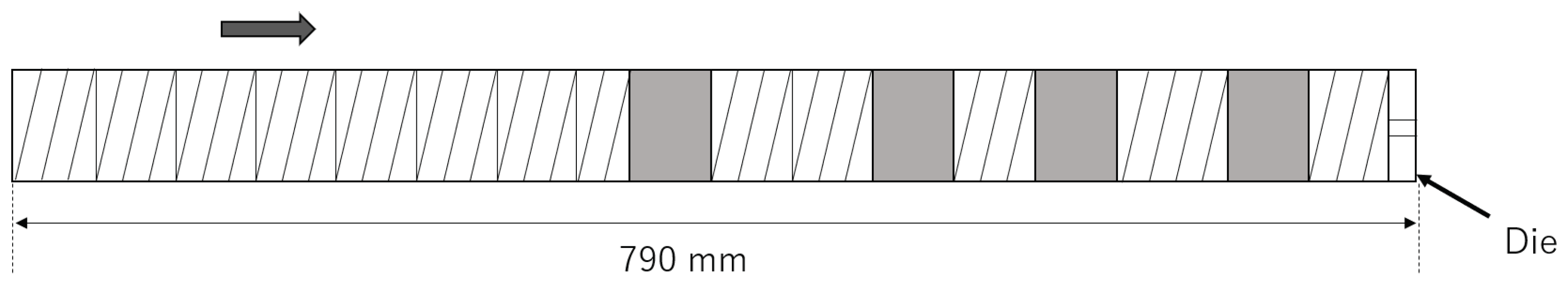
2.1.1. Screw
2.1.2. Die
2.2. Model of Viscosity Reduction
2.3. Numerical Calculation
3. Experiment
3.1. System
3.2. Materials
3.3. Investigation of Nusselt Number
3.4. Degradation of PP with High-Shear Extruder
3.4.1. Experiment 1
3.4.2. Experiment 2
4. Results
4.1. Investigation of Nusselt Number
4.2. Degradation of PP with High-Shear Extruder
5. Conclusions
Author Contributions
Funding
Conflicts of Interest
Appendix A. Nomenclature and Definition of Symbols
| A | frequency factor in the kinetic model of viscosity reduction [Pa · s] |
| heat capacity of resin [J/(kg·K)] | |
| D | inner diamenter of the barrel [m] |
| E | activation energy of thermal decomposition [J/mol] |
| f | fill ratio [-] |
| H | height of the screw channel [m] |
| k | reaction rate of thermal decomposition [1/s] |
| l | length of the die [m] |
| path length of the screw [m] | |
| ratio of total length of screw to inner diameter of barrel in an extruder [-] | |
| n | exponent in the Cross model [-] |
| number of polymers with number of nodes [-] | |
| N | screw rotational speed [1/s] |
| number of nodes of a linear polymer [-] | |
| number average degree of polymerization [-] | |
| average Nusselt number [-] | |
| local Nusselt number at z [-] | |
| p | pressure of resin [Pa] |
| q | heat flux [W/m] |
| Q | flow rate [m/s] |
| r | radial coordinate of the die [m] |
| R | radius of the die [m] |
| gas constant = 8.31 J/(mol · K) | |
| S | cross-sectional area of the screw channel or die [m] |
| t | time [s] |
| T | temperature of resin [K] |
| barrel temperature [K] | |
| exit temperature of the high-shear extruder [K] | |
| reference temperature [K] | |
| temperature of the die [K] | |
| model parameter of the zero-shear viscosity [K] | |
| z-component of the fluid velocity [m/s] | |
| V | velocity of the barrel with respect to an observer on the screw [m/s] |
| z-component of V [m/s] | |
| W | width of the screw channel [m] |
| x | coordinate of the channel width direction of the screw [m] |
| X | weight fraction in TGA analysis [-] |
| y | coordinate of the channel depth direction of the screw [m] |
| z | coordinate for down-channel direction or axial direction of the screw [m] |
| pressure gradient [Pa/m] | |
| heating rate in TGA analysis [C/min] | |
| shear rate of resin [1/s] | |
| non-Newtonian viscosity of resin [Pa·s] | |
| zero-shear viscosity in the Cross model [Pa·s] | |
| zero-shear viscosity at [Pa·s] | |
| value of at the exit of the high-shear extruder [Pa·s] | |
| thermal conductivity of resin [W/(m·K)] | |
| melt density of resin [kg/m] | |
| shear stress of resin [Pa] | |
| characteristic shear stress in the Cross model [Pa] | |
| screw angle [rad] |
Appendix B. Setup of Twin-Screw Extruder

| Q [kg/h] | N [min] |
|---|---|
| 4.8 | 80 |
| 10 | 100 |
References
- Dutton, K.C. Overview and analysis of the meltblown process and parameters. J. Text. Apparel Technol. Manage. 2009, 6, 1–25. [Google Scholar]
- Takarada, W.; Hatano, S.; Kikutani, T. Experimental and Numerical Analysis of Unstable Behavior of Melt Blowing Process. J. Fiber Sci. Technol. 2020, 76, 208–216. [Google Scholar] [CrossRef]
- Berzin, F.; Vergnes, B.; Dufossé, P.; Delamare, L. Modeling of peroxide initiated controlled degradation of polypropylene in a twin screw extruder. Polym. Eng. Sci. 2000, 40, 344–356. [Google Scholar] [CrossRef]
- Vergnes, B.; Berzin, F. Peroxide-controlled Degradation of Poly(propylene): Rheological Behaviour and Process Modelling. Macromol. Symp. 2000, 158, 77–90. [Google Scholar] [CrossRef]
- Iedema, P.D.; Willems, C.; van Vliet, G.; Bunge, W.; Mutsers, S.; Hoefsloot, H. Using molecular weight distributions to determine the kinetics of peroxide-induced degradation of polypropylene. Chem. Eng. Sci. 2001, 56, 3659–3669. [Google Scholar] [CrossRef]
- Iedema, P.D.; Remerie, K.; van der Ham, M.; Biemond, E.; Tacx, J. Controlled peroxide-induced degradation of polypropylene in a twin-screw extruder: Change of molecular weight distribution under conditions controlled by micromixing. Chem. Eng. Sci. 2011, 66, 5474. [Google Scholar] [CrossRef]
- Cassagnau, P.; Bounor-Legaré, V.; Vergnes, B. Experimental and modelling aspects of the reactive extrusion process. Mech. Ind. 2019, 20, 803. [Google Scholar] [CrossRef] [Green Version]
- Shimizu, H.; Li, Y.; Kaito, A.; Sano, H. Formation of Nanostructured PVDF/PA11 Blends Using High-Shear Processing. Macromolecules 2005, 38, 7880–7883. [Google Scholar] [CrossRef]
- Li, Y.; Shimizu, H. High-shear processing induced homogeneous dispersion of pristine multiwalled carbon nanotubes in a thermoplastic elastomer. Polymer 2007, 48, 2203–2207. [Google Scholar] [CrossRef]
- Li, Y.; Shimizu, H. Fabrication of Nanostructured Polycarbonate/Poly(methyl methacrylate) Blends With Improved Optical and Mechanical Properties by High-Shear Processing. Polym. Eng. Sci. 2011, 51, 1437. [Google Scholar] [CrossRef]
- Louizi, M.; Massardier, V.; Cassagnau, P. Contribution of High-shear Processing to the Compatibilization of (PP/EPR)/PE Ternary Blends. Macromol. Mater. Eng. 2014, 299, 674–688. [Google Scholar] [CrossRef]
- Ishigami, A.; Kodama, Y.; Suenaga, H.; Inoue, T.; Ito, H. Mechanical Properties and Structure of Novel Polymer Blends and Composites Fabricated by Reactive and High-shear Rotational Processing. Energy Procedia 2016, 89, 30–37. [Google Scholar] [CrossRef] [Green Version]
- Kim, B.; White, J.L. Simulation of Thermal Degradation, Peroxide Induced Degradation, and Maleation of Polypropylene in a Modular Co-Rotating Twin Screw Extruder. Polym. Eng. Sci. 1997, 37, 576. [Google Scholar] [CrossRef]
- Farahanchi, A.; Sobkowicz, M.J. Kinetic and process modeling of thermal and mechanical degradation in ultrahigh speed twin screw extrusion. Polym. Degrad. Stab. 2017, 138, 40–46. [Google Scholar] [CrossRef] [Green Version]
- Blancas, C.; Vargas, L. Modeling of the industrial process of peroxide-initiated polypropylene (homopolymers) controlled degradation. J. Macromol. Sci. 2001, B40, 315–326. [Google Scholar] [CrossRef]
- Fel, E.; Massardier, V.; Mélis, F.; Vergnes, B.; Cassagnau, P. Residence Time Distribution in a High Shear Twin Screw Extruder. Int. Polym. Proc. 2014, 29, 71–80. [Google Scholar] [CrossRef]
- Bird, R.B.; Armstrong, R.C.; Hassager, O. Fluid Mechanics. Dynamics of Polymeric Liquids, 2nd ed.; John Wiley and Sons Inc: New York, NY, USA, 1987; Volume 1. [Google Scholar]
- Rubinstein, M.; Colby, R.H. Polymer Physics; Oxford University Press Inc.: New York, NY, USA, 2003. [Google Scholar]
- Suehiro, T.; O’shima, E. A kinetic study on the random scission of a polymer. Kobunshi Ronbunshu. 1977, 34, 241–248. [Google Scholar] [CrossRef]
- Chan, J.H.; Balke, S.T. The thermal degradation kinetics of polypropylene: Part III. Thermogravimetric analyses. Polym. Degrad. Stab. 1997, 57, 135–149. [Google Scholar] [CrossRef]


| Sample | [Pa· s] | [K] | [Pa] | n |
|---|---|---|---|---|
| PP1 | ||||
| PP2 |
| N [min] | [ C] | [ C] | ||
|---|---|---|---|---|
| Sim | Exp | |||
| 100 | 195 | 8.92 | 216 | 213 |
| 100 | 300 | 10.9 | 280 | 290 |
| (8.92) | (274) | |||
| 1000 | 195 | 15.1 | 318 | 287 |
| (8.92) | (328) | |||
| 2000 | 195 | 17.2 | 375 | 307 |
| (8.92) | (393) | |||
| N [min] | [°C] | [°C] | [Pa· s] | |||
|---|---|---|---|---|---|---|
| Sim. | Exp. | Sim. | Exp. | Sim. | Exp. | |
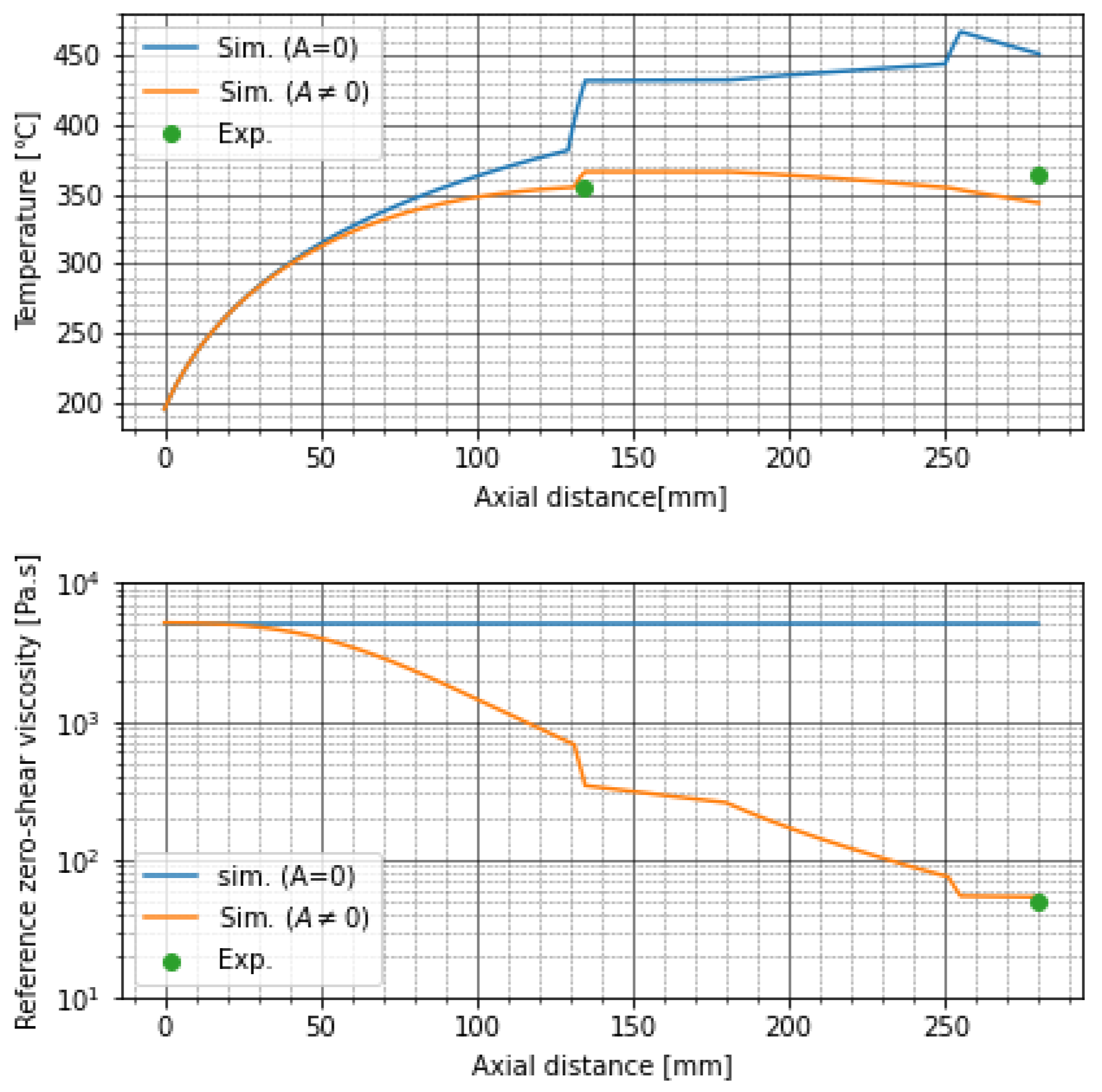
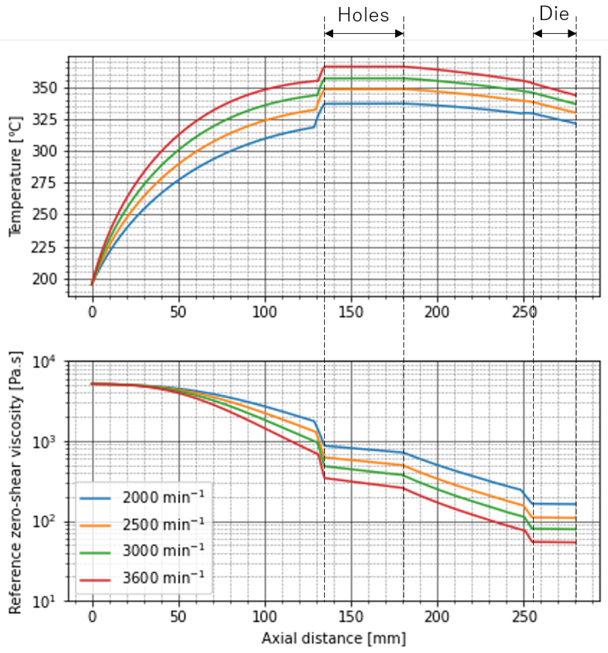
| 2000 | 337 | 343 | 322 | 351 | 162 | 143 |
| 2500 | 348 | 352 | 330 | 360 | 109 | 113 |
| 3000 | 356 | 346 | 337 | 364 | 78.6 | 76.1 |
| 3600 | 366 | 355 | 344 | 365 | 53.8 | 48.2 |
| [°C] | [°C] | [Pa · s] | ||
|---|---|---|---|---|
| Sim. | Exp. | Sim. | Exp. | |
| 300 | 341 | 375 | 12.8 | 16.9 |
| 350 | 365 | 380 | 5.25 | 5.51 |
Publisher’s Note: MDPI stays neutral with regard to jurisdictional claims in published maps and institutional affiliations. |
© 2021 by the authors. Licensee MDPI, Basel, Switzerland. This article is an open access article distributed under the terms and conditions of the Creative Commons Attribution (CC BY) license (https://creativecommons.org/licenses/by/4.0/).
Share and Cite
Sasai, Y.; Iizuka, Y.; Osada, K.; Taki, K. Controlled Degradation of Commercial Resin for Meltblown Nonwoven Fabric Sheet Production. Polymers 2021, 13, 3892. https://doi.org/10.3390/polym13223892
Sasai Y, Iizuka Y, Osada K, Taki K. Controlled Degradation of Commercial Resin for Meltblown Nonwoven Fabric Sheet Production. Polymers. 2021; 13(22):3892. https://doi.org/10.3390/polym13223892
Chicago/Turabian StyleSasai, Yuya, Yoshio Iizuka, Kaho Osada, and Kentaro Taki. 2021. "Controlled Degradation of Commercial Resin for Meltblown Nonwoven Fabric Sheet Production" Polymers 13, no. 22: 3892. https://doi.org/10.3390/polym13223892
APA StyleSasai, Y., Iizuka, Y., Osada, K., & Taki, K. (2021). Controlled Degradation of Commercial Resin for Meltblown Nonwoven Fabric Sheet Production. Polymers, 13(22), 3892. https://doi.org/10.3390/polym13223892