
Conjugated Polymer Films Having a Uniaxial Molecular Orientation and Network Structure Prepared by Electrochemical Polymerization in Liquid Crystals


Abstract

1. Introduction
2. Experimental
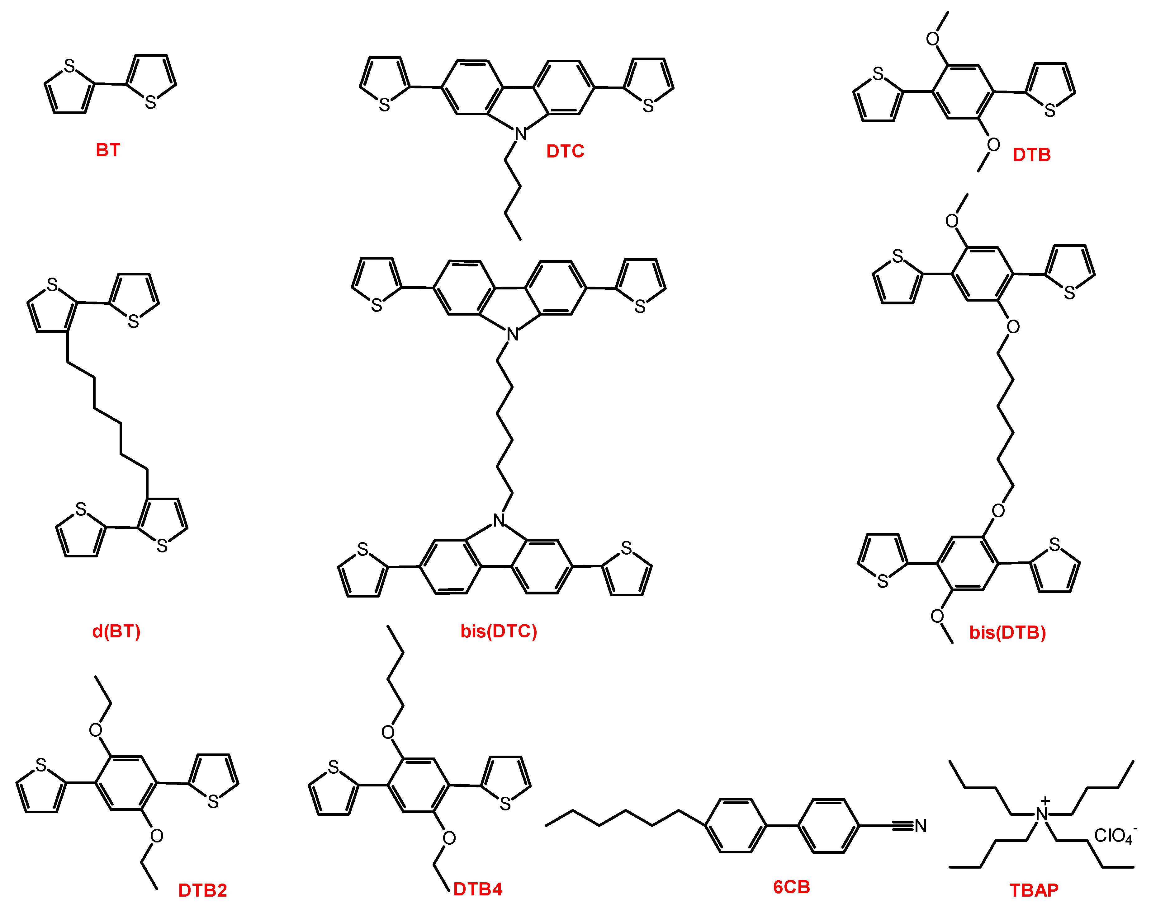
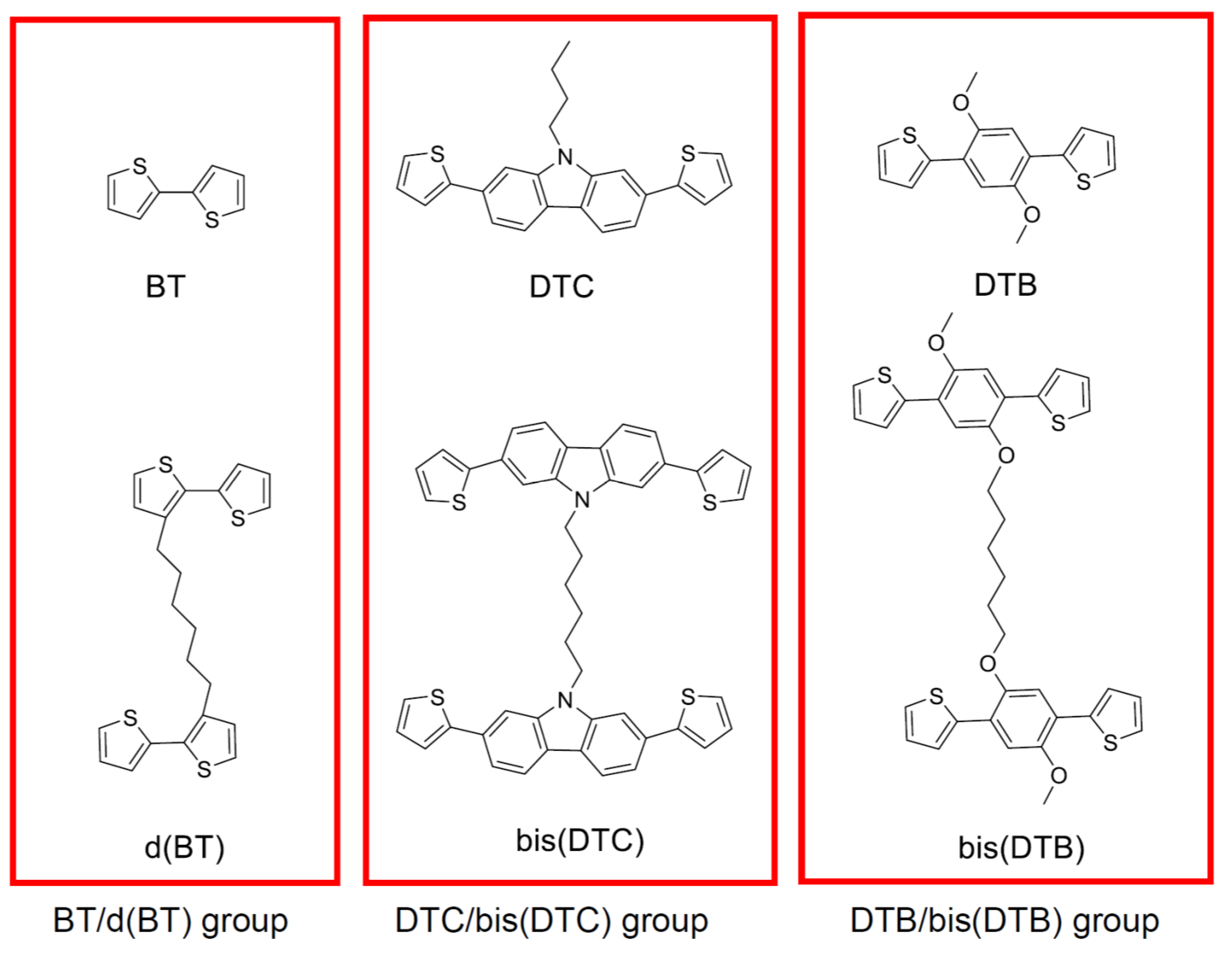
2.1. Materials
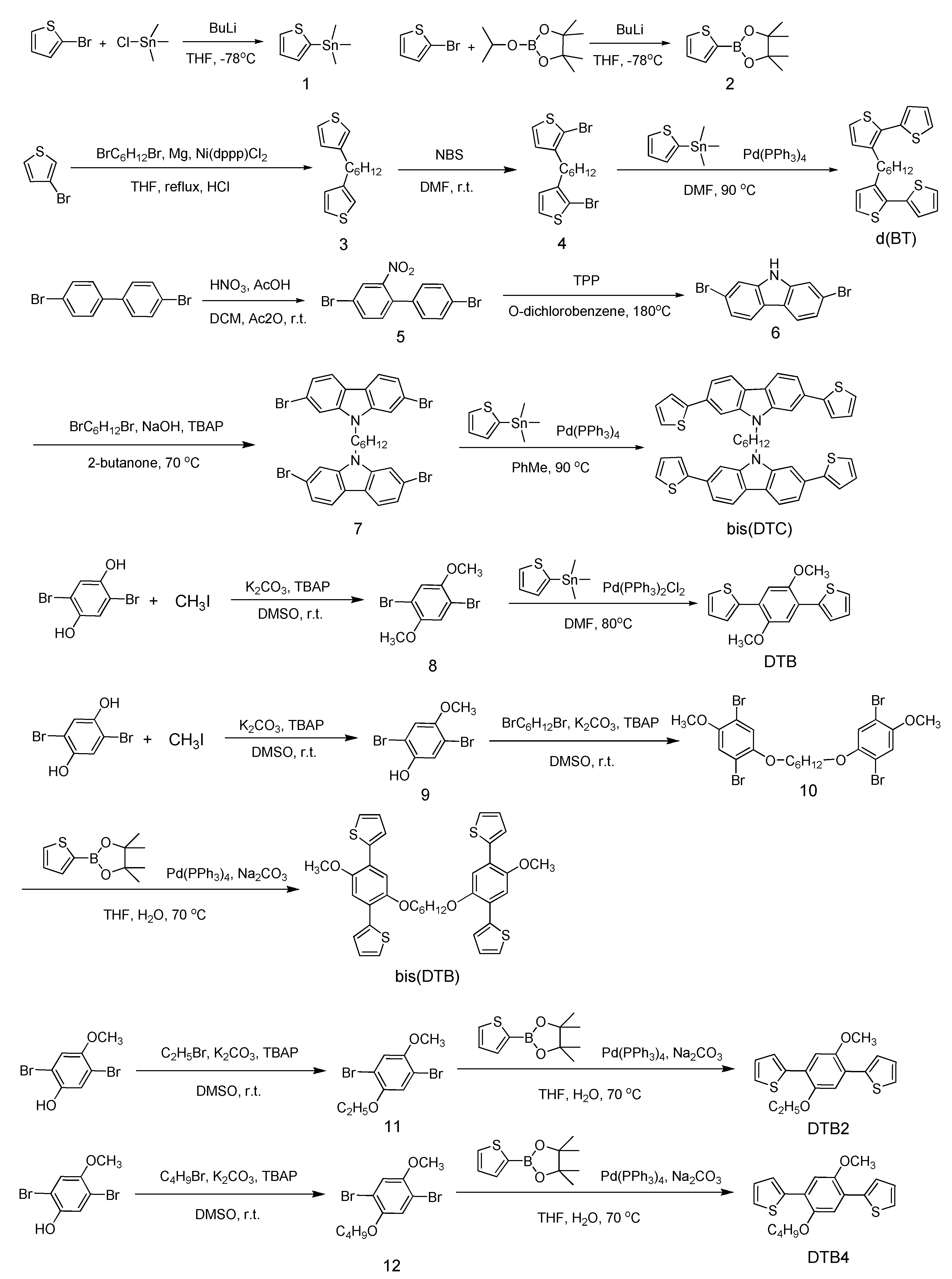
2.2. Synthesis
2.2.1. Trimethyl(thiophen-2-yl)stannane (1)
2.2.2. 4,4,5,5-Tetramethyl-2-(thiophen-2-yl)-1,3,2-dioxaborolane (2)
2.2.3. 1,6-Di(thiophen-3-yl)hexane (3)
2.2.4. 1,6-Bis(2-bromothiophen-3-yl)hexane (4)
2.2.5. 1,6-Di(2,2′-bithiophen-3-yl)hexane (d(BT))
2.2.6. 4,4′-Dibromo-2-nitro-biphenyl (5)
2.2.7. 2,7-Dibromo-9H-carbazole (6)
2.2.8. 1,6-Bis(2,7-dibromo-9H-carbazol-9yl)hexane (7)
2.2.9. 1,6-Bis(2,7-di(thiophen-2-yl)-9H-carbazol-9-yl)hexane (bis(DTC))
2.2.10. 1,4-Dibromo-2,5-bis-methoxybenzene (8)
2.2.11. 1,4-Dimethoxy-2,5-di(thiophen-2-yl)benzene (DTB)
2.2.12. 2,5-Dibromo-4-methoxyphenol (9)
2.2.13. 1,6-Bis(2,5-dibromo-4-methoxyphenoxy)hexane (10)
2.2.14. 1,6-Bis(4-methoxy-2,5-di(thiophen-2-yl)phenoxy)hexane (bis(DTB))
2.2.15. 1,4-Dibromo-2-ethoxy-5-methoxybenzene (11)
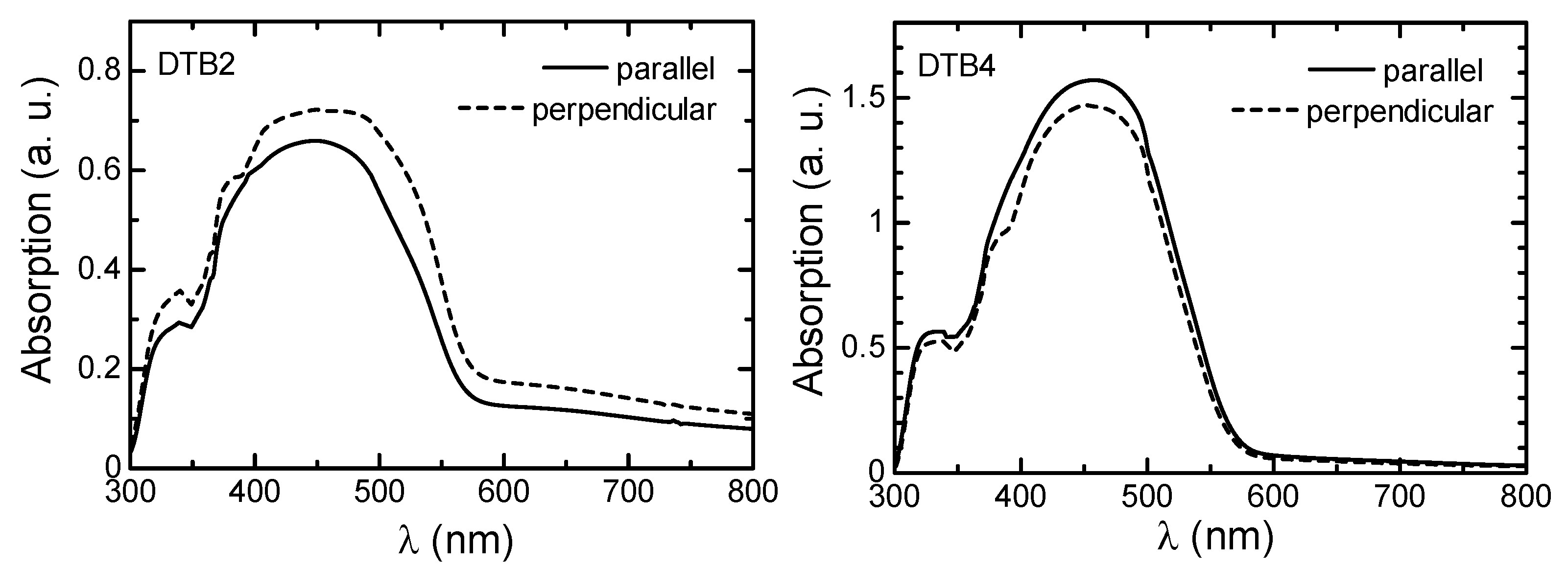
2.2.16. 2,2′-(2-Ethoxy-5-methoxy-1,4-phenylene)dithiophene (DTB2)
2.2.17. 1,4-Dibromo-2-butoxy-5-methoxybenzene (12)
2.2.18. 1-Butoxy-4-methoxy-2,5-di(thiophen-2-yl)benzene (DTB4)
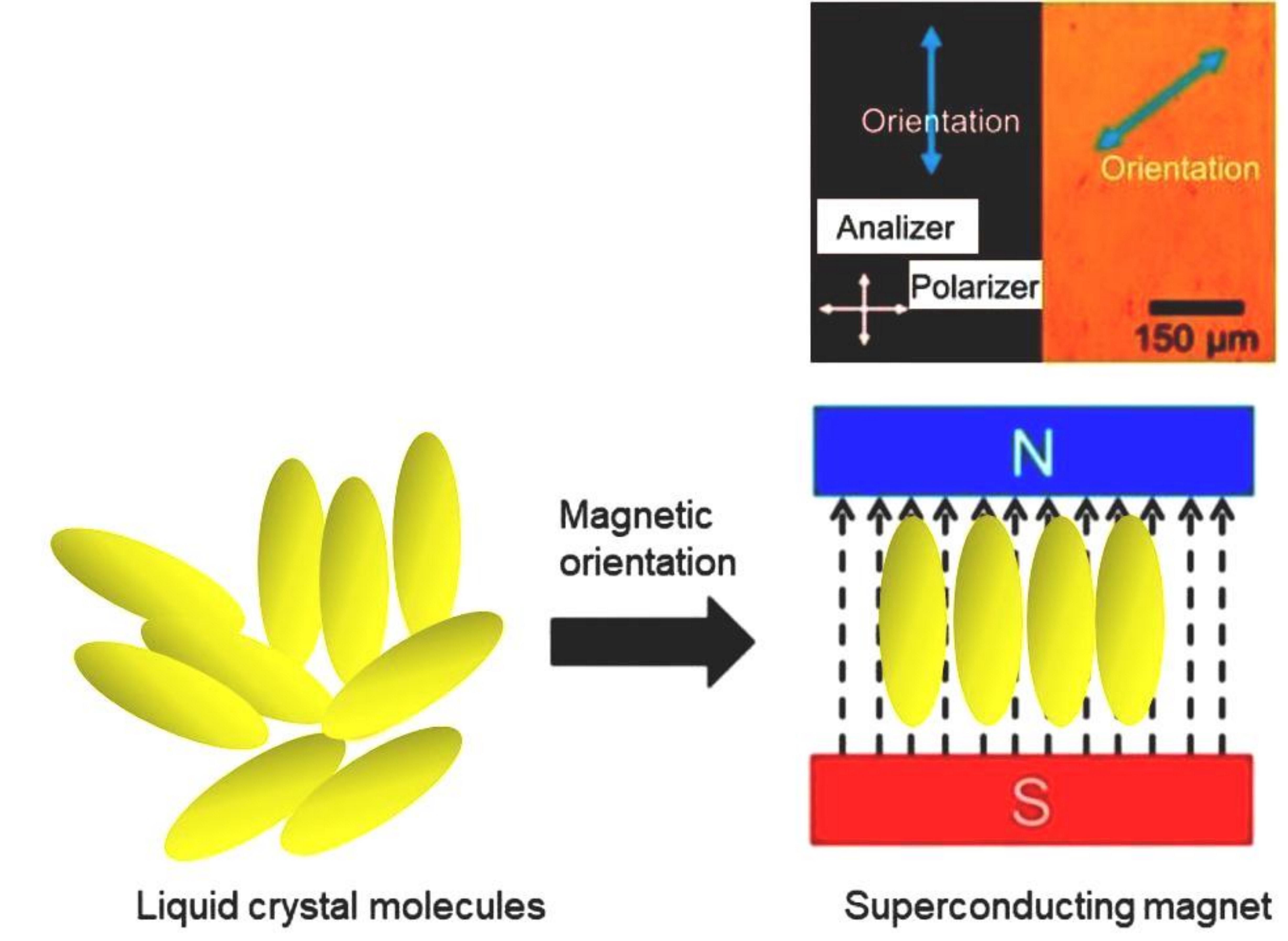
2.3. Electrochemical Polymerization in LCs
2.4. Characterization Methods
3. Results
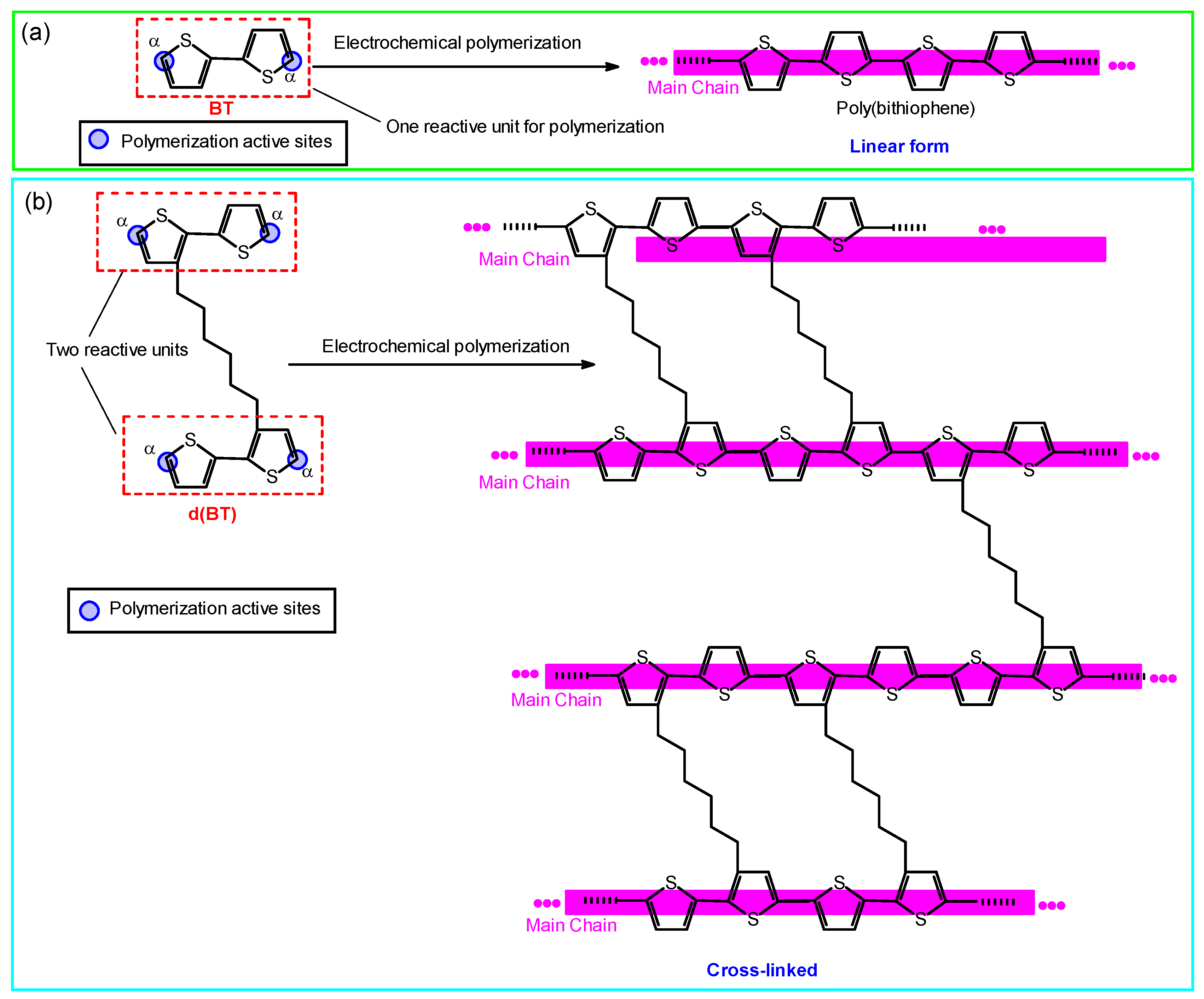
3.1. Polymerization
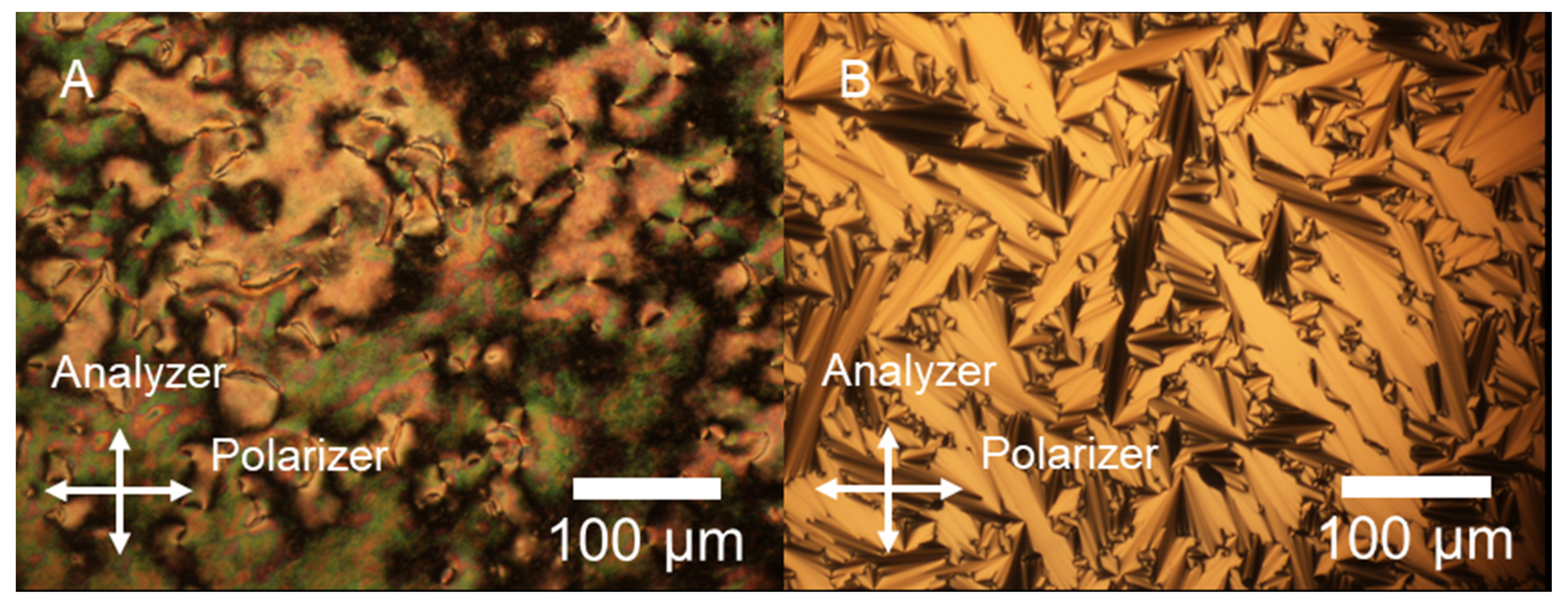
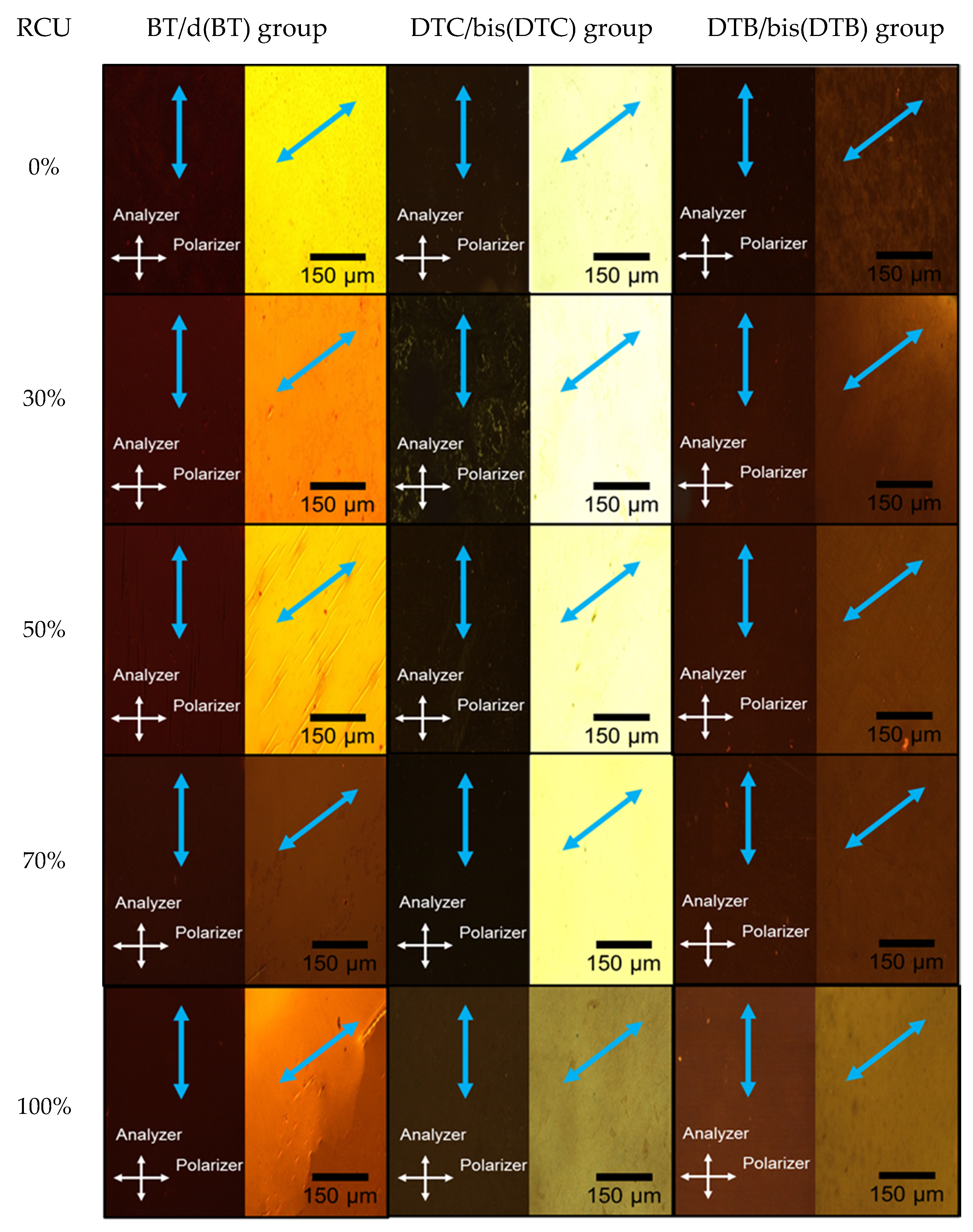
3.2. POM Observation
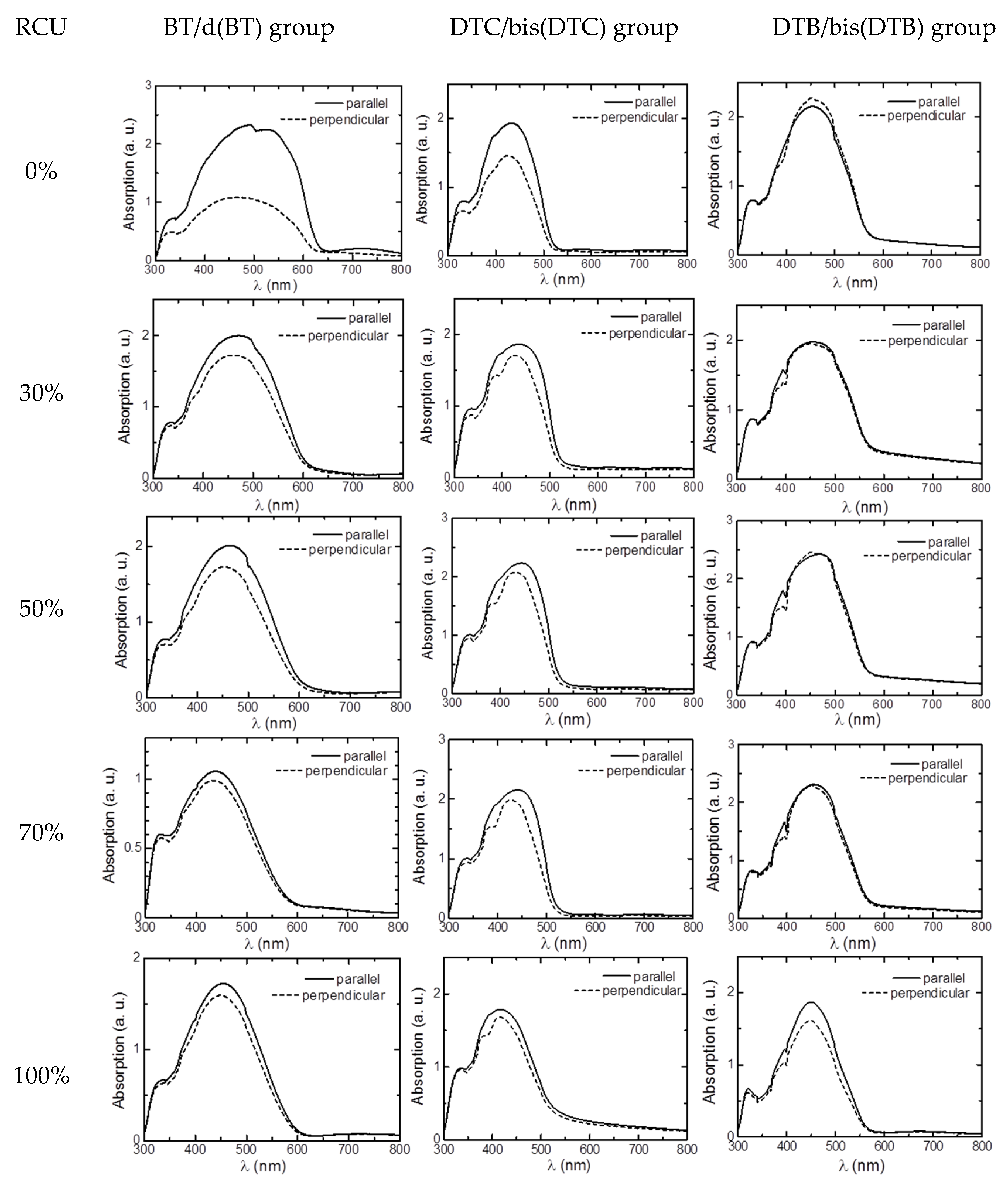
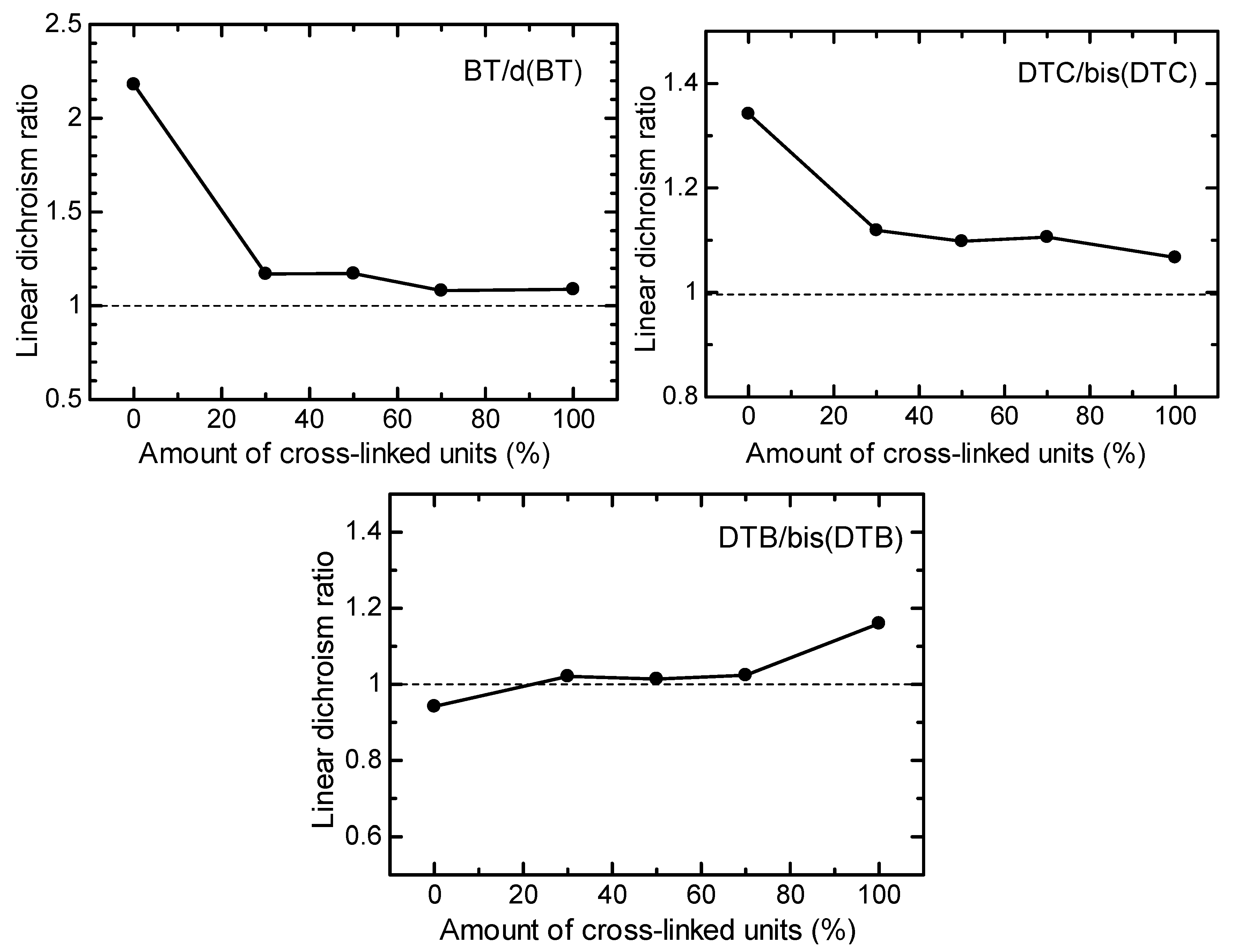
3.3. LD UV–Vis Absorption Spectra Measurement
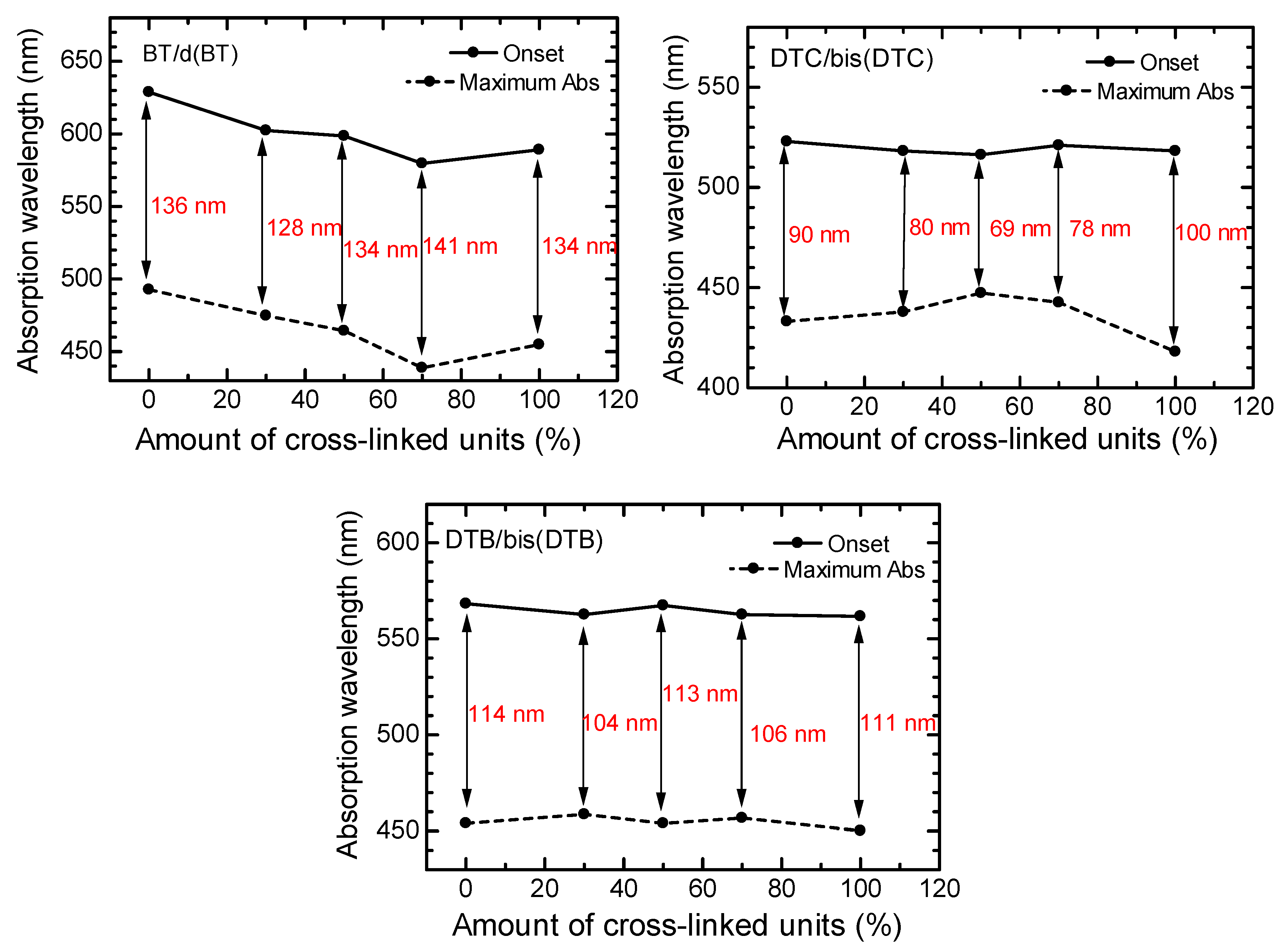
3.4. Optical Properties of Polymers
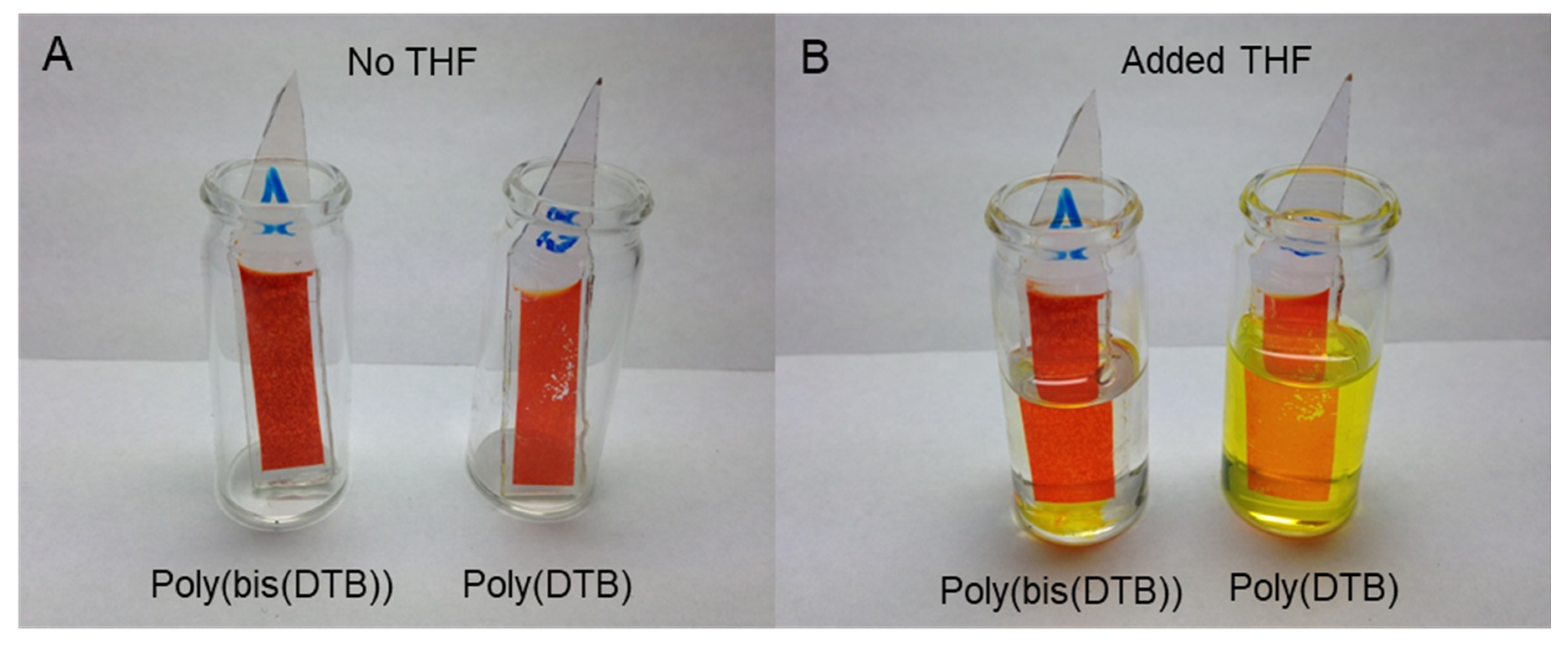
3.5. Solvent Resistance
4. Conclusions
5. Instruments
Author Contributions
Funding
Institutional Review Board Statement
Informed Consent Statement
Acknowledgments
Conflicts of Interest
References
- Horie, M.; Majewski, L.; Fearn, M.J.; Yu, C.-Y.; Luo, Y.; Song, A.; Saunders, B.R.; Turner, M. Cyclopentadithiophene based polymers—A comparison of optical, electrochemical and organic field-effect transistor characteristics. J. Mater. Chem. 2010, 20, 4347–4355. [Google Scholar] [CrossRef]
- McCulloch, I.; Ashraf, R.S.; Biniek, L.; Bronstein, H.; Combe, C.; Donaghey, J.E.; James, D.I.; Nielsen, C.B.; Schroeder, B.C.; Zhang, W. Design of Semiconducting Indacenodithiophene Polymers for High Performance Transistors and Solar Cells. Acc. Chem. Res. 2012, 45, 714–722. [Google Scholar] [CrossRef] [PubMed]
- Tanaka, H.; Watanabe, S.-I.; Ito, H.; Marumoto, K.; Kuroda, S.-I. Direct observation of the charge carrier concentration in organic field-effect transistors by electron spin resonance. Appl. Phys. Lett. 2009, 94, 103308. [Google Scholar] [CrossRef]
- Guo, X.; Zhang, M.; Huo, L.; Xu, F.; Wua, Y.; Hou, J. Design, synthesis and photovoltaic properties of a new D–π–A polymer with extended π-bridge units. J. Mater. Chem. 2012, 22, 21024–21031. [Google Scholar] [CrossRef]
- Baek, N.S.; Hau, S.K.; Yip, H.-L.; Acton, O.; Chen, K.-S.; Jen, A. High Performance Amorphous Metallated π-Conjugated Polymers for Field-Effect Transistors and Polymer Solar Cells. Chem. Mater. 2008, 20, 5734–5736. [Google Scholar] [CrossRef]
- Osken, I.; Gundogan, A.S.; Tekin, E.; Eroglu, M.S.; Ozturk, T. Fluorene—Dithienothiophene-S,S-dioxide copolymers. Fine-tuning for OLED applications. Macromolecules 2013, 46, 9202–9210. [Google Scholar] [CrossRef]
- Zhao, Q.; Bai, Y.; Fan, Z.; Wang, P.; Li, J.; Li, D.; Zhang, X. Synthesis and characterization of a novel fluorene-alt-carbazole polymer to host green, blue, and red phosphorescence. J. Appl. Polym. Sci. 2015, 133. [Google Scholar] [CrossRef]
- Ahn, T.; Lee, S.-G.; Shim, H.-K. Systematic approach of blue-light-emitting copolymers by introducing various naphthalene linkages into fluorene containing PPV derivatives. Opt. Mater. 2003, 21, 191–197. [Google Scholar] [CrossRef]
- Gather, M.C.; Bradley, D.D.C. An improved optical method for determining the order parameter in thin oriented molecu-lar films and demonstration of a highly axial dipole moment for the lowest energy π–π* optical transition in poly(9,9-dioctylfluorene-co-bithiophene). Adv. Funct. Mater. 2007, 17, 479–485. [Google Scholar] [CrossRef]
- Dudenko, D.; Kiersnowski, A.; Shu, J.; Pisula, W.; Sebastiani, D.; Spiess, H.W.; Hansen, M.R. A Strategy for Revealing the Packing in Semicrystalline π-Conjugated Polymers: Crystal Structure of Bulk Poly-3-hexyl-thiophene (P3HT). Angew. Chem. 2012, 124, 11230–11234. [Google Scholar] [CrossRef]
- King, S.; Vaughan, H.; Monkman, A. Orientation of triplet and singlet transition dipole moments in polyfluorene, studied by polarised spectroscopies. Chem. Phys. Lett. 2007, 440, 268–272. [Google Scholar] [CrossRef]
- Kleinhenz, N.; Rosu, C.; Chatterjee, S.; Chang, M.; Nayani, K.; Xue, Z.; Kim, E.; Middlebrooks, J.; Russo, P.S.; Park, J.O.; et al. Liquid Crystalline Poly(3-hexylthiophene) Solutions Revisited: Role of Time-Dependent Self-Assembly. Chem. Mater. 2015, 27, 2687–2694. [Google Scholar] [CrossRef]
- Oosterbaan, W.D.; Vrindts, V.; Berson, S.; Guillerez, S.; Douheret, O.; Ruttens, B.; D’Haen, J.; Adriaensens, P.; Manca, J.; Lutsen, L.; et al. Efficient formation, isolation and characterization of poly(3-alkylthiophene) nanofibres: Probing order as a function of side-chain length. J. Mater. Chem. 2009, 19, 5424–5435. [Google Scholar] [CrossRef]
- Huang, Y.; Guo, X.; Liu, F.; Huo, L.; Chen, Y.; Russell, T.P.; Han, C.C.; Li, Y.; Hou, J. Improving the ordering and photovol-taic properties by extending π–conjugated area of electron-donating units in polymers with D-A structure. Adv. Mater. 2012, 24, 3383–3389. [Google Scholar] [CrossRef]
- Koynov, K.; Bahtiar, A.; Ahn, T.; Cordeiro, R.M.; Ho1rhold, H.-H.; Bubeck, C. Molecular weight dependence of chain orien-tation and optical constants of thin films of the conjugated polymer MEH-PPV. Macromolecules 2006, 39, 8692–8698. [Google Scholar] [CrossRef]
- Bae, J.W.; Song, K. Anisotropic charge-carrier mobilities of liquid crystalline conjugated polymers on photo-aligned PVCN dielectric insulators. Org. Electron. 2016, 30, 143–148. [Google Scholar] [CrossRef]
- Yuan, K.; Chen, L.; Chen, Y. Photovoltaic performance enhancement of P3HT/PCBM solar cells driven by incorporation of conjugated liquid crystalline rod-coil block copolymers. J. Mater. Chem. C 2014, 2, 3835–3845. [Google Scholar] [CrossRef]
- Wang, A.; Kawabata, K.; Goto, H. Synthesis of isothianaphthene (ITN) and 3,4-ethylenedioxy-thiophene (EDOT)-based low-band gap liquid crystalline conjugated polymers. Materials 2013, 6, 2218–2228. [Google Scholar] [CrossRef]
- Liu, C.; Tan, Y.; Li, C.; Wu, F.; Chen, L.; Chen, Y. Enhanced power-conversion efficiency in inverted bulk heterojunction so-lar cells using liquid-crystal-conjugated polyelectrolyte interlayer. ACS Appl. Mater. Int. 2015, 7, 19024–19033. [Google Scholar] [CrossRef] [PubMed]
- Tong, X.; Han, D.; Fortin, D.; Zhao, Y. Highly Oriented Nanofibrils of Regioregular Poly(3-hexylthiophene) Formed via Block Copolymer Self-Assembly in Liquid Crystals. Adv. Funct. Mater. 2012, 23, 204–208. [Google Scholar] [CrossRef]
- Moggio, I.; Moigne, J.L.; Arias-Marin, E.; Issautier, D.; Thierry, A.; Comoretto, D.; Dellepiane, G.; Cuniberti, C. Orientation of polydiacetylene and poly(π-phenylene ethynylene) films by epitaxy and rubbing. Macromolecules 2001, 34, 7091–7099. [Google Scholar] [CrossRef]
- Kanbara, T.; Mori, C.; Wakayama, H.; Fukuda, T.; Zhou, Z.-H.; Maruyama, T.; Osakada, K.; Yamamoto, T. Orientation of linear π-conjugated poly(π-phenylene), poly(thiophene-2,5-diyl) and poly(2,2’-Bipyridine-5,5’-diyl) perpendicular to the surface of carbon and metal substrates. Factors controlling the orientation. Solid State Commun. 1992, 83, 771–774. [Google Scholar] [CrossRef]
- Kim, N.-J.; Kwon, J.-H.; Kim, M. Highly Oriented Self-Assembly of Conducting Polymer Chains: Extended-Chain Crystallization during Long-Range Polymerization. J. Phys. Chem. C 2013, 117, 15402–15408. [Google Scholar] [CrossRef]
- Yang, S.Y.; Shin, K.; Park, C.E. The Effect of Gate-Dielectric Surface Energy on Pentacene Morphology and Organic Field-Effect Transistor Characteristics. Adv. Funct. Mater. 2005, 15, 1806–1814. [Google Scholar] [CrossRef]
- Kline, R.J.; McGehee, M.D. Morphology and Charge Transport in Conjugated Polymers. J. Macromol. Sci. Part C 2006, 46, 27–45. [Google Scholar] [CrossRef]
- Davis, A.R.; Carter, K.R. Controlling Optoelectronic Behavior in Poly(fluorene) Networks Using Thiol–Ene Photo-Click Chemistry. Macromolecules 2015, 48, 1711–1722. [Google Scholar] [CrossRef]
- Yang, Q.-D.; Cheng, Y.; Li, H.-W.; Liu, J.; Cheung, S.-H.; So, S.-K.; Wong, K.-W.; Lau, W.-M.; Tsang, S.-W. Locking the morphology with a green, fast and efficient physical cross-linking approach for organic electronic applications. Org. Electron. 2016, 28, 53–58. [Google Scholar] [CrossRef]
- Clement, S.; Meyer, F.; Winter, J.D.; Coulembier, O.; Velde, C.M.L.V.; Zeller, M.; Gerbaux, P.; Balandier, J.-Y.; Sergeyev, S.; Lazzaroni, R.; et al. Synthesis and supramolecular organization of regioregular polythiophene block oligomers. J. Org. Chem. 2010, 75, 1561–1568. [Google Scholar] [CrossRef]
- Wakabayashi, R.; Kaneko, K.; Takeuchi, M.; Shinkai, S. Toward the alignment of conjugated polymers into anisotropically-ordered structure. New J. Chem. 2007, 31, 790–799. [Google Scholar] [CrossRef]
- Ling, X.; Pritzker, M.D.; Burns, C.M.; Byerley, J.J. A Mechanism for Electropolymerization of 2-Vinylpyridine Coatings on Metal Surfaces. Macromolecules 1998, 31, 9134–9140. [Google Scholar] [CrossRef]
- Waltman, R.J.; Bargon, J. Electrically conducting polymers: A review of the electropolymerization reaction, of the effects of chemical structure on polymer film properties, and of applications towards technology. Can. J. Chem. 1986, 64, 76–95. [Google Scholar] [CrossRef]
- Li, C.; Sun, C.; Chen, W.; Pan, L. Electrochemical thin film deposition of polypyrrole on different substrates. Surf. Coat. Technol. 2005, 198, 474–477. [Google Scholar] [CrossRef]
- Liao, J.; Wu, S.; Yin, Z.; Huang, S.; Ning, C.; Tan, G.; Chu, P.K. Surface-Dependent Self-Assembly of Conducting Polypyrrole Nanotube Arrays in Template-Free Electrochemical Polymerization. ACS Appl. Mater. Interfaces 2014, 6, 10946–10951. [Google Scholar] [CrossRef] [PubMed]
- Panasyuk, T.L.; Mirsky, V.; Piletsky, S.; Wolfbeis, O.S. Electropolymerized Molecularly Imprinted Polymers as Receptor Layers in Capacitive Chemical Sensors. Anal. Chem. 1999, 71, 4609–4613. [Google Scholar] [CrossRef]
- Sharm, P.S.; Pietrzyk-Le, A.; D’Souza, F.; Kutner, W. Electrochemically synthesized polymers in molecular imprinting for chemical sensing. Anal. Bioanal. Chem. 2012, 402, 3177–3204. [Google Scholar] [CrossRef] [PubMed]
- Carbas, B.B.; Kivrak, A.; Teke, E.; Zora, M.; Önal, A.M. Electrochemical polymerization of a new low-voltage oxidized thienylenepyrrole derivative and its electrochromic device application. J. Electroanal. Chem. 2014, 729, 15–20. [Google Scholar] [CrossRef]
- Gu, C.; Dong, W.; Yao, L.; Lv, Y.; Zhang, Z.; Lu, D.; Ma, Y. Cross-Linked Multifunctional Conjugated Polymers Prepared by In Situ Electrochemical Deposition for a Highly-Efficient Blue-Emitting and Electron-Transport Layer. Adv. Mater. 2012, 24, 2413–2417. [Google Scholar] [CrossRef] [PubMed]
- Lv, Y.; Yao, L.; Gu, C.; Xu, Y.; Liu, D.; Lu, D.; Ma, Y. Electroactive self-assembled monolayers for enhanced efficiency and stabil-ity of electropolymerized luminescent films and devices. Adv. Funct. Mater. 2011, 21, 2896–2900. [Google Scholar] [CrossRef]
- Yan, W.; Li, Y.; Sun, W.; Peng, H.; Ye, S.; Liu, Z.; Bian, Z.; Huang, C. High-performance hybrid perovskite solar cells with polythiophene as hole-transporting layer via electrochemical polymerization. RSC Adv. 2014, 4, 33039–33046. [Google Scholar] [CrossRef]
- Goto, H.; Nimori, S. Liquid crystal electropolymerisation under magnetic field and resultant linear polarised electrochromism. J. Mater. Chem. 2010, 20, 1891–1898. [Google Scholar] [CrossRef]
- Dong, J.; Kawabata, K.; Goto, H. Synthesis and characterization of a novel donor–acceptor–donor chiral inducer and its ap-plication in electrochemical polymerization. J. Mater. Chem. C 2015, 3, 2024–2032. [Google Scholar] [CrossRef]
- Kawabata, K.; Takeguchi, M.; Goto, H. Optical activity of heteroaromatic conjugated polymer films prepared by asymmetric electrochemical polymerization in cholesteric liquid crystals: Structural function for chiral induction. Macromolecules 2013, 46, 2078–2091. [Google Scholar] [CrossRef]
- Goto, H. Liquid crystal stepwise electropolymerization–an approach to create insect photonic structure. RSC Adv. 2013, 3, 6347–6355. [Google Scholar] [CrossRef]
- Yoneyama, H.; Tsujimoto, A.; Goto, H. Preparation of optically active pyridine-based conducting polymer films using a liquid crystal electrolyte containing a cholesterol derivative. Macromolecules 2007, 40, 5279–5283. [Google Scholar] [CrossRef]
- Kawabata, K.; Nimori, S.; Goto, H. Horizontal and vertical orientation of polythiophenes by electrochemical polymerization in magnetically aligned smectic liquid crystal. ACS Macro Lett. 2013, 2, 587–591. [Google Scholar] [CrossRef]
- Kawabata, K.; Goto, H. Electrosynthesis of 2,7-linked polycarbazole derivatives to realize low-band gap electroactive polymers. Synth. Met. 2010, 160, 2290–2298. [Google Scholar] [CrossRef]


| Component | Liquid Crystal | Supporting Salt | Reaction Units |
|---|---|---|---|
| Molar concentration | 99% | 0.50% | 0.50% |
| Reaction time | 15 min | ||
| Voltage | 4 V direct current | ||
| Magnetic field intensity | 12 T | ||
| Temperature | rt. | ||
| Electrode substrate | ITO glass | ||
Publisher’s Note: MDPI stays neutral with regard to jurisdictional claims in published maps and institutional affiliations. |
© 2021 by the authors. Licensee MDPI, Basel, Switzerland. This article is an open access article distributed under the terms and conditions of the Creative Commons Attribution (CC BY) license (https://creativecommons.org/licenses/by/4.0/).
Share and Cite
Dong, J.; Nimori, S.; Goto, H. Conjugated Polymer Films Having a Uniaxial Molecular Orientation and Network Structure Prepared by Electrochemical Polymerization in Liquid Crystals. Polymers 2021, 13, 2425. https://doi.org/10.3390/polym13152425
Dong J, Nimori S, Goto H. Conjugated Polymer Films Having a Uniaxial Molecular Orientation and Network Structure Prepared by Electrochemical Polymerization in Liquid Crystals. Polymers. 2021; 13(15):2425. https://doi.org/10.3390/polym13152425
Chicago/Turabian StyleDong, Jiuchao, Shigeki Nimori, and Hiromasa Goto. 2021. "Conjugated Polymer Films Having a Uniaxial Molecular Orientation and Network Structure Prepared by Electrochemical Polymerization in Liquid Crystals" Polymers 13, no. 15: 2425. https://doi.org/10.3390/polym13152425
APA StyleDong, J., Nimori, S., & Goto, H. (2021). Conjugated Polymer Films Having a Uniaxial Molecular Orientation and Network Structure Prepared by Electrochemical Polymerization in Liquid Crystals. Polymers, 13(15), 2425. https://doi.org/10.3390/polym13152425