
Stress Distribution and Fracture Toughness of Underground Reinforced Plastic Pipe Composite


1
Mechanical Engineering Department, College of Engineering and Islamic Architecture, Umm Al-Qura University, Makkah 21421, Saudi Arabia
2
Mechanical Engineering Department, Faculty of Engineering, South Valley University, Qena 83521, Egypt
3
Mechanical Engineering Department, King Saud University, Riyadh 11421, Saudi Arabia
*
Authors to whom correspondence should be addressed.
Polymers 2021, 13(13), 2194; https://doi.org/10.3390/polym13132194
Submission received: 2 June 2021
/
Revised: 26 June 2021
/
Accepted: 29 June 2021
/
Published: 30 June 2021
(This article belongs to the Special Issue Fiber-Reinforced Polymers (FRPs))
Abstract
:Reinforced composite materials have many applications in the aerospace, marine, and petroleum industries. Glass fiber-reinforced pipes are of considerable importance as pressurized vessels, infrastructure materials, and petroleum wastewater pipelines. The stress intensity factor due to through-thickness discontinuities is a major parameter in fracture mechanics to understand the failure mechanisms in glass fiber-composite pipes. The stress intensity factor is calculated for a composite cylinder subjected to internal pressure using the linear extended finite element method based on the law of energy release evaluation of surface damage. The analytical model needs two material properties; they are the tensile strength and the fracture toughness; therefore, a standard tensile test was carried out on a standard specimen taken from the pipe’s wall thickness. Moreover, the compact tension test specimen was manufactured from the pipe’s wall thickness to obtain the fracture toughness. The average tensile strength was measured as 21.5 MPa with a standard deviation of 5.59 MPa, moreover, the average Young’s modulus was measured as 32.75 GPa with a standard deviation of 6.64 GPa. The fracture toughness was measured as 2322 () with a standard deviation of 142.5 (), whereas the average surface release energy () was 153.6 kJ/m2 with a standard deviation of 22.53 kJ/m2. A valuable design equation was extracted from the finite element model to measure the effect of cracks on the hoop stress of the cylinder wall thickness based on a nonlinear model. Moreover, an acceptable equation was used to calculate the correction and shape factor of a cylinder with movable and unmovable through-thickness cracks. This study provides useful tools and guidance for the design and analysis of composite cylinders.
1. Introduction
Glass fiber-composite pipes play a dominant role in the infrastructure of any petroleum field and are an attractive alternative to metallic pipes in many industries. These pipes consist of glass fiber and thermosetting resin, and in many cases, quartz particles are added to form a sandwich composite material, which is generally made using the filament winding technique. Composite pipes have many applications, including pressure pipelines and water transportation over and underground [1,2,3]. The degradation of the fracture and mechanical properties of GRP pipes after immersing in a corrosive medium (solution of sodium chloride in water) was reported [2,4]. This degradation was attributed to the corrosion occurrence utilizing a corrosive medium for only composite pipes.
Wastewater influences the tensile and flexural strength and fracture toughness of reinforced-composite pipes in the petroleum field [2]. The decrease in these properties compromises the safety of pressurized pipes, and the existence of small cracks throughout the pipes’ wall thickness may cause abrupt failures. Rafiee and Ghorbanhosseini [5] investigated the creep and long-term properties of composite pipes under internal pressure and transverse compression loading. Other works on compression creep were carried out by Farshad and Necola [5,6], but the pipe material was conditioned in water at ambient temperature before testing, and it was found that the properties were negatively affected. In addition, water has a detrimental effect on the flexural strength of glass fiber-reinforced pipes depending on the air conditions [7]. Composite pipes are distinguished by their low cost and corrosion resistance, but the decrease in strength is a significant problem; Miao et al. [8], for example, coated a composite with basalt fiber and epoxy resin, achieving good results. The hygrothermal effect and bending properties of composite pipes modified with graphene nanoplatelets to increase their service life were studied by Firouzsalari et al. [9]. Dong [10] studied the failure of composite pipes and measured residual stresses using a finite element model. Moreover, the effects of the layup and fiber orientation were studied. Another finite element study [11,12] investigated the effect of thickness, winding direction, and the number of fabric plies of composite cylinders under internal pressure on the characteristic mechanical properties using the analytical finite element method. The hoop stress distribution or the circumferential thickness tensile strength was calculated numerically and experimentally using a split-disk test method [13], which was based on a progressive damage model through finite element analysis of a cracked disk. A nondestructive analytical model based on vibration modal analysis was extracted by Abdellah et al. [14] to predict the nominal strength and fracture properties of glass fiber-composite laminates. A direct link between the specimen densities and the dimensional accuracy with orientation was observed [15]. Moreover, the angular orientation led to significant anisotropic behavior in terms of fracture toughness of single edge notch samples. The effect of seawater aging and curing on similar polymer-composite cylinders used as the marine structure was evaluated [16]. Completely cured composite cylinders had significant mechanical properties compared with partially cured ones. Besides, aging in seawater for a certain time resulted in enhancing both hoop strength and stiffness, which again was not critical for radial strength. Similarly, the hardness and density of the same cylinders under seawater exposure were investigated and were found to be changed with the effect of seawater presence [17]. Moreover, the effect of seawater on steel pipes that were rehabilitated with layers of fiberglass and epoxy was studied [18]. The hoop strength of pipes being repaired before and after immersion increased, indicating the need for a greater thickness of composite repair for complete rehabilitation.
The mechanical properties of composite cylinder material were measured using standard tensile strength [19] to be implemented in a finite element analysis which was used to calculate the static performance of the composite cylinder. Through the numerical study, the stress analysis and Von Mises stress were obtained. Composite cylinder pipes which were reinforced by E-glass and T300/934 were investigated [20] under pressurized medium to obtain the hoop and radial stress induced through the cylinder wall thickness. The composite cylinder with particular characteristics was used in compressed hydrogen storage applications [21]. For more focus on fracture mechanics, the notch effect on cylinders under internal pressure was considered [22]. The failure modes of the composite cylinder were investigated not only under the effect of internal pressure but also under the effect of low-velocity impact [23] using the layer-wise theory through progressive damage model. Delamination and bad damage were observed in composite pipes under static and impact load [24]. Rapid damage was in the critical load for a drop weight impact of a composite tube reinforced by fibers, therefore higher incident energy was revealed [25]. Glass/carbon functionally graded filament wound composite pipes under low-velocity impact and internal pressure were studied by Gemi et al. [26]. Delamination was observed on the outer surfaces of the pipes, moreover matrix cracking. Valuable finite element analysis was extracted to predict the mechanical properties and behaviors of the composite cylinder under pressure vessels, it was shown that high-density polyethylene (HDPE) was very attractive and had a good bearing and high-stress capacity, moreover, it was recommended that FEM was a good tool for simulating the pressurized composite cylinder [27]. Carbon-reinforced epoxy composite pipes were numerically and experimentally investigated under an external pressure, finite element model and an evaluation damage model was developed. Buckling and in-plane shear modes with delamination were observed [28].
The composite layup of composite pipes influenced their mechanical properties, a progressive damage model [29], was derived to predict the failure behavior of composite laminates with different layups and stacking sequences. The investigation used progressive continuum mechanics and the experimental results gave a robust technique to understanding the carbon fiber reinforced pipes failure mechanisms.
The flexural stiffness of thick-walled composite pipes was experimentally studied by Geuchy and Hoa [30], it was revealed the relation between experimental and theoretical results, moreover, it was given a great difference between the strength of material concept and elasticity concepts.
The relationship between the structural properties of the shell and the end bearing capacity (UBC) on fiberglass reinforced mortar tubes (GRP) was simulated [31]. It was observed that the UBC was in a growing pipeline with an increase in the proportion of the size of the fibers and the proportion of the volume of the spirally wound layer, but UBC increased with the layers of tubules.
On the other hand, the effect of thermal aging on the compression behavior of interlocking polymer network composites reinforced with fiberglass was discussed. The strength of these pipes decreased slightly with increasing temperature and concerning the corresponding aging period. Besides, the thermal conductivity of the glass fabric composite epoxy laminates was enhanced using hetero-structured BNN-30@BNNS fillers, the fillers accelerated the heat flow transfer [32].
A comparison between the carbon and energy footprint of nonmetallic composite pipes in onshore oil and gas flowlines was investigated using Life Cycle Assessment (LCA) analysis [33]. It was reported that a stronger and high-strength fiber, such as carbon fiber, gave better weight safety for pipes.
Not only do polymer matrix composites have attractive and competitive roles in aerospace industries but also lately they have been inserted into the transmission of electromagnetic waves and protective antenna [34]. These types of polymers, matrix reinforced with other advanced fibers such as PBO fibers [35], but these types of fiber may need a special coating to increase adhesiveness at the interfacial interface by the cyanate ester polymer [36]. Another fiber proposed for use in this advanced process is dopamine/POSS functionalized Kevlar cloth may be more compatible for wave transmission [37].
The Novelty and Objectives of the Present Study
In the present study, the stress intensity factor of a composite cylinder with a crack was studied, based on an extended finite element model, which requires two parameters: the traction separation at which the crack propagates and the damage evaluation, which requires knowledge of the surface release energy. Therefore, a tensile test of the cylinder thickness was carried out and compact tension test specimens were performed.
Therefore, the main goals of the present study are as follows:
- Measure the stress intensity factor of the cracked cylinder using the extended finite element model.
The paper is organized as follows: mathematical theory, the finite element model, results and discussion, conclusion.
2. Mathematical Model
The mode I stress intensity factor at the free surface of crack can be calculated by Newman [39] as follows:
where is the hoop stress through the cylinder wall thickness (t), (a) is the crack length, (b) is the crack width through the thickness (rectangular or straight crack), Q is the shape factor, and R is the cylinder inner radius. The hoop stress for an unnotched thin cylinder (t/d < 20) or through-thickness unopen crack can be measured using Equation (2) [40]:
The longitudinal stress is half of the hoop stress, assuming closed-end cylinders. For open through-thickness cracks with straight lines (rectangular cracks in Figure 1), the hoop stress would be dependent on the crack length; therefore, the FEM was implemented and the stress intensity equation by Newman was modified as follows:
Factor Y is the total effective parameter correction factor or influence function, which can be measured as follows:
3. Extended Finite Element Model (XFEM)
Belytschko and Black [41] recently developed the XFEM. The main idea of the XFEM is based on the work of Melenk and Babuska [42] who used the concept of partition of the finite element unity and enrichment function. XFEM is distinguished because the mesh does not have to be updated to follow the crack path [43], and therefore, the need to mesh and re-mesh the complex discontinuity surfaces is reduced. The analysis of a fracture can be performed with considerable numerical accuracy as the crack propagates around the crack tip without re-meshing and refinement; for a complete description, see [44].
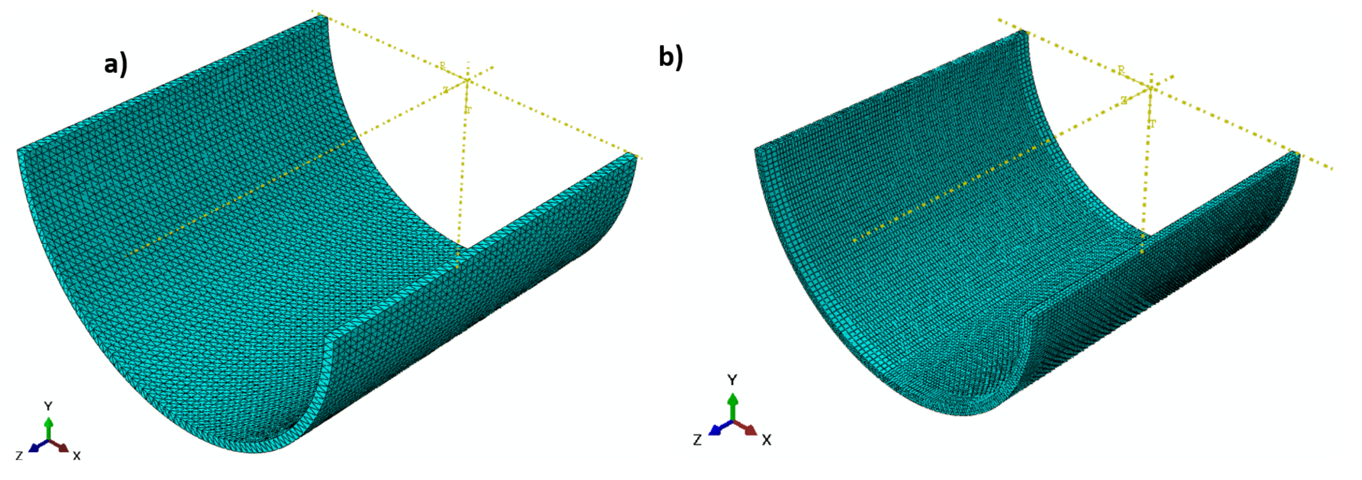
The 3D nonlinear elastic FEM is based on the basic extended fracture method. A cylindrical domain (520.7 mm diameter × 500 mm) was created as a solid part (see Figure 2 a). A straight rectangular planar strip (a × 13 mm) was implemented. Crack lengths (a) of 10, 20, 30, 40, 50, and 60 mm were investigated. The crack was movable for the calculation of the measured hoop stress through-thickness and crack propagation behavior under an internal pressure . To calculate the stress intensity factor using the linear elastic extended finite element method, the crack was fixed and kept unmovable. The material used for the composite cylinder was based on DN 500 and SN 1000 [45]. The maximum principal stress corresponded to the unnotched nominal strength, which was measured as 30 MPa. The damage evaluation criterion is the maximum fracture energy (185 kJ/m2) and the independent mixed-mode that is applicable. A 10-node quadratic tetrahedron shape (47288) C3D10 element type with 10 global sizes was used for an unnotched cylinder (see Figure 3a). Additionally, 38412 C3D8R elements with an approximately hexagonal shape with a global size of 10 and 5 for region B were used in the domain, as shown in Figure 3b. The displacement boundary condition technique was applied at both ends of the cylinder cracked domain (see Figure 2b) for internal pressure.
4. Experimental Work
The previous numerical model required the mechanical properties of the cylinder wall thickness; therefore, a tension test was carried out to obtain the composite Young’s modulus and tensile strength. The fracture toughness and related longitudinal surface energy release for fiber tension were needed to evaluate the damage model implemented in the FEM.
4.1. Material Description
The present study used glass fiber-reinforced polymer pipes with a heterogeneous structure consisting of random matt, roving, unsaturated polyester resin, and sand according to the values displayed in Figure 4 and listed in Table 1. An unsaturated polyester resin brings environmental and chemical resistance, it also bonds the fiber in the pipe structure. Unsaturated polyesters are less expensive than other resins used in GRP pipe manufacturing but provide a slight strength and chemical resistance. It is often an economical choice for a less demanding, low-pressure service.
The glass fiber composite pipes were manufactured using the common filament winding technology. The GRP has a complex structure, inner and outer surface layers. Then the barrier and chop layer end by the structured layers in the outer and inner surfaces, where inbetween quartz sand was placed. For a complete description of the manufacturing process return to [18]. The composite material mainly depends on the fiber geometry, lay-up thickness, fiber pretension, and the quality of the manufacturing process.
These constituent compositions were obtained using the ignition removal technique, according to the standard ASTM D3171-99 [15]. These types of pipes are used in pipelines for chemical wastewater used in the petroleum field. The fiber shape and size are illustrated in Figure 5a, and the grains of quartz sand and shapes are shown in Figure 5b. The elastic properties of the glass fiber composite pipes (GRP) are listed in Table 2. The equivalent Young’s modulus is 35.15 GPa, which is calculated based on Reference [46] and experimental tensile data.
Although the pipes are taken ex situ, and they were in service for a period of time, this action would not affect the results of the mathematical model because the model depends on the as-received input data, and the validation was carried out on the as-received experimental data of the material of the in situ pipe.
4.2. Tension Test
Tension tests were performed on specimens manufactured from glass fiber-reinforced polymer pipe wall thicknesses (DN = 520.7 mm and 13 mm thickness). Four specimens were tested. These four specimens were cut from the wall of the composite pipes using a diamond coated disk to obtain the final dimension which is shown in Figure 6. A curvature of 10 mm radius was created at the corner of the specimen to distribute uniformly the stress through the cross-section of the specimens. The width of the specimen was selected to be as minimal as possible to decrease the large curvature. These tests were performed according to ASTM D3039 [47] using a universal testing machine (machine model WDW-100) with a load capacity of 20 kN and a controlled speed of 2 mm/min. Figure 6 shows the standard specimen geometry for tension.
4.3. Fracture Toughness Test
The fracture toughness of such materials is more important, as the occurrence of any crack will cause the absorption of water through the GRP pipe sandwich. This can cause harmful corrosion, which may subsequently result in degradation. Therefore, fracture toughness is an attractive parameter to be measured. The corresponding surface release energy GIC was needed in the previous derived analytical model. One type of fracture toughness test on the specimens was used according to ASTM standard D 5045 [48]. The crack resistance must be measured so as to be stopped at the onset of degradation and obtain satisfactory fracture toughness results. The three compact tension specimens were machined using a diamond-coated disk from the wall material of glass fiber reinforced pipes (GRP pipes) according to the dimensions given in ASTM D 5045, as shown in Figure 7. The loading holes were then drilled using tungsten carbide drills while clamping the specimen between two sacrificial plates of the same material to prevent damage and delamination. A 10 mm starter crack was created using a fine razor blade. The crack face was given a scaled mark. The thickness of the specimen was 13 mm.
5. Results and Discussion
The tensile test results are shown in Figure 8, which shows that the curved section of the cylinder material had an average strength of 21.5 MPa with a standard deviation 5.59 MPa. The average Young’s modulus was 32.75 GPa with a standard deviation 6.64 GPa. The curve was not smooth and had a stepwise behavior, attributed to fiber bridging (pull-out), fiber failure as shown in the SEM image in Figure 9a. The fracture was nearly ductile as pores in the matrix are observed in Figure 9b. In a focus observation of the curve behavior, all specimens nearly had the closest elongation, the curve trend was not entirely linear, and there was some plasticity or hardening because the composite material is considered a quasi-brittle material [49,50,51,52], which was distinguished by a moderate plastic zone ahead of the crack tip. There were also two specimens with black and red colours similar to two knees (two lowering points), which corresponded to the first and second fiber failure in the transverse direction [53]. Redistribution of stress between longitudinal fibers and matrix led to a drastic nonlinear increment [54] in the tensile stresses with a tensile modulus lower than that for the initial linear portion. The final failure was catastrophic without any yielding.
The load–displacement curve for a standard compact tension test specimen is needed to complete the specific failure mechanisms of the curved wall thickness of the cylinder to measure its fracture toughness. Crack growth was neither smooth nor continuous; instead, several crack jumps of a few millimetres each time were observed, as shown in Figure 10. The peak load, , which was 5% according to the standard ASTM D 5045, was determined [48]. This load corresponded to the maximum load capacity of the material before failure. The peak load values for the three specimens were inserted into Equation (5) to calculate the mode I fracture toughness () values (). According to the standard ASTM E399 [55], the critical stress intensity factor for a fracture load () is given by
where (t) is specimen thickness, mm; (w) is specimen width, mm; (a) is crack length, mm; () is the load at 5% secant; and () is the shape correction factor:
The critical energy release rate of the laminate can be calculated from as follows [56,57]:
where Ex, Ey, Gxy, and are Young’s modulus in the (x) and (y) directions (see Figure 7), the shear modulus, and the Poisson’s ratio of the laminate, respectively, which are listed in Table 2. The equivalent young () is calculated as follows [46]:
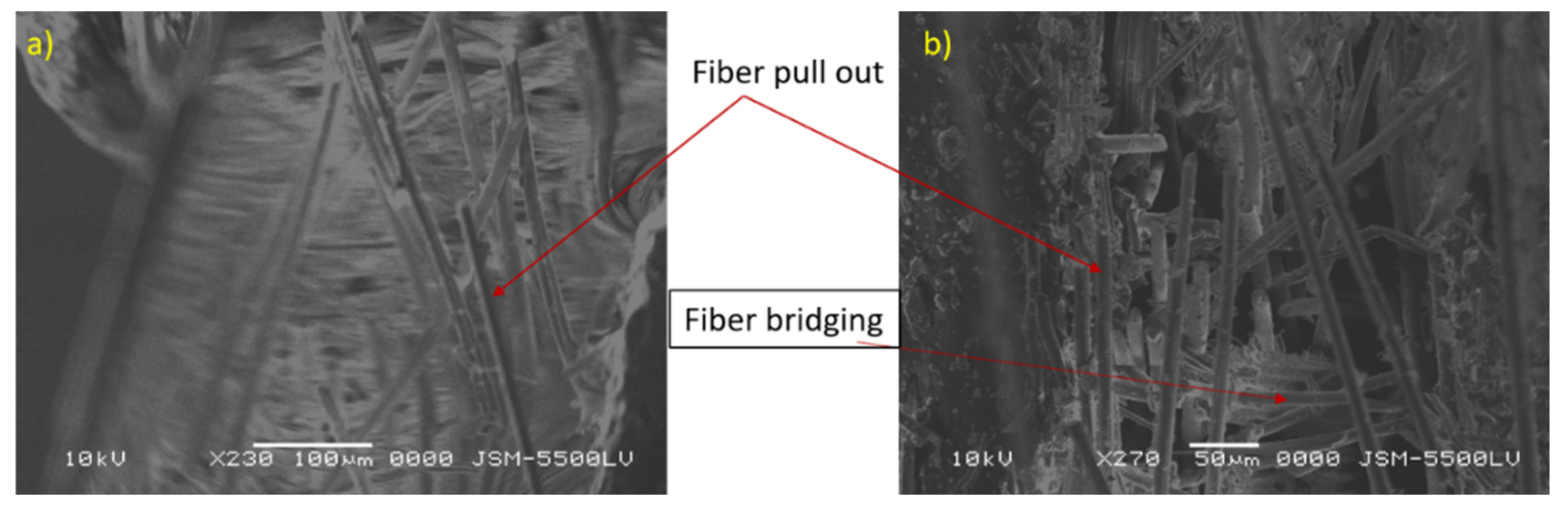
After substituting these reduction data, Young’s modulus was calculated to be 35.15 GPa, which is very close to the average experimental Young’s modulus (32.75 GPa). The optically observed failure crack length reached 22.5 mm. The average fracture toughness () was measured as 2322 () with a standard deviation 142.5 (). The average surface release energy () is 153.6 kJ/m2 with a standard deviation 22.53 kJ/m2. It was observed that the fiber bridged the two faces of cracks, and the crack advanced straight through the precrack direction, owing to the high-stress intensity factor induced at the crack tip. The existence of cracks in the pipe surface or even macrocracks may be harmful and cause leakage of the petroleum waste fluids into the pipe core quartz particles, which can be dangerous [2]. Fiber pull out, fiber fracture, fiber bridging, and matrix cracking, are shown in Figure 11. The sand quartz has the major role in this trend of behavior. The sand core material in the cylinder is distinguished by high stiffness and brittleness, especially when combined by epoxy resin. The curvature of the specimen had a dominating role in the increase of the fracture toughness values. The curvature of the specimen redistributed the loading stress through the cross-section of the tested specimens.
The variation of the tensile strength values of each of the four specimens ranged from 30 MPa to 14 MPa for specimen number 1 and 4 respectively, this variation was due to an error in the specimen preparation, machine stiffness, misalignment error, the maximum variation percent were nearly 50% while minimum percent was 30%, this is because of the difficulty of curved surfaced deformation and machining. This range decreased in the case of the compact tension test specimens which were 1.8 kN to 1.5 kN (see Figure 10). This was because in the compact tension test the load decreased after reaching critical values.
This variation as previously mentioned is not a problem, and its effect on the mathematical model is slight because the model used the as-received input data, which were fed to the ABAQUS software.
Mathematical Model Results
The stress distribution over the composite cylinder’s thickness is illustrated in Figure 12 for different through-thickness cracks. The hoop stress in the wall thickness of the cylinder was calculated using Lame’s Equation (2), [38]; it was determined to be 300.4 MPa for the uncracked cylinder. Cracks through the wall thickness are the major reason for the failure and damage of any cylinder with internal pressure or external pressure [39]. Therefore, the values of the hoop stress in the through-thickness movable crack are fitted in Figure 13 with the following logarithmic Equation:
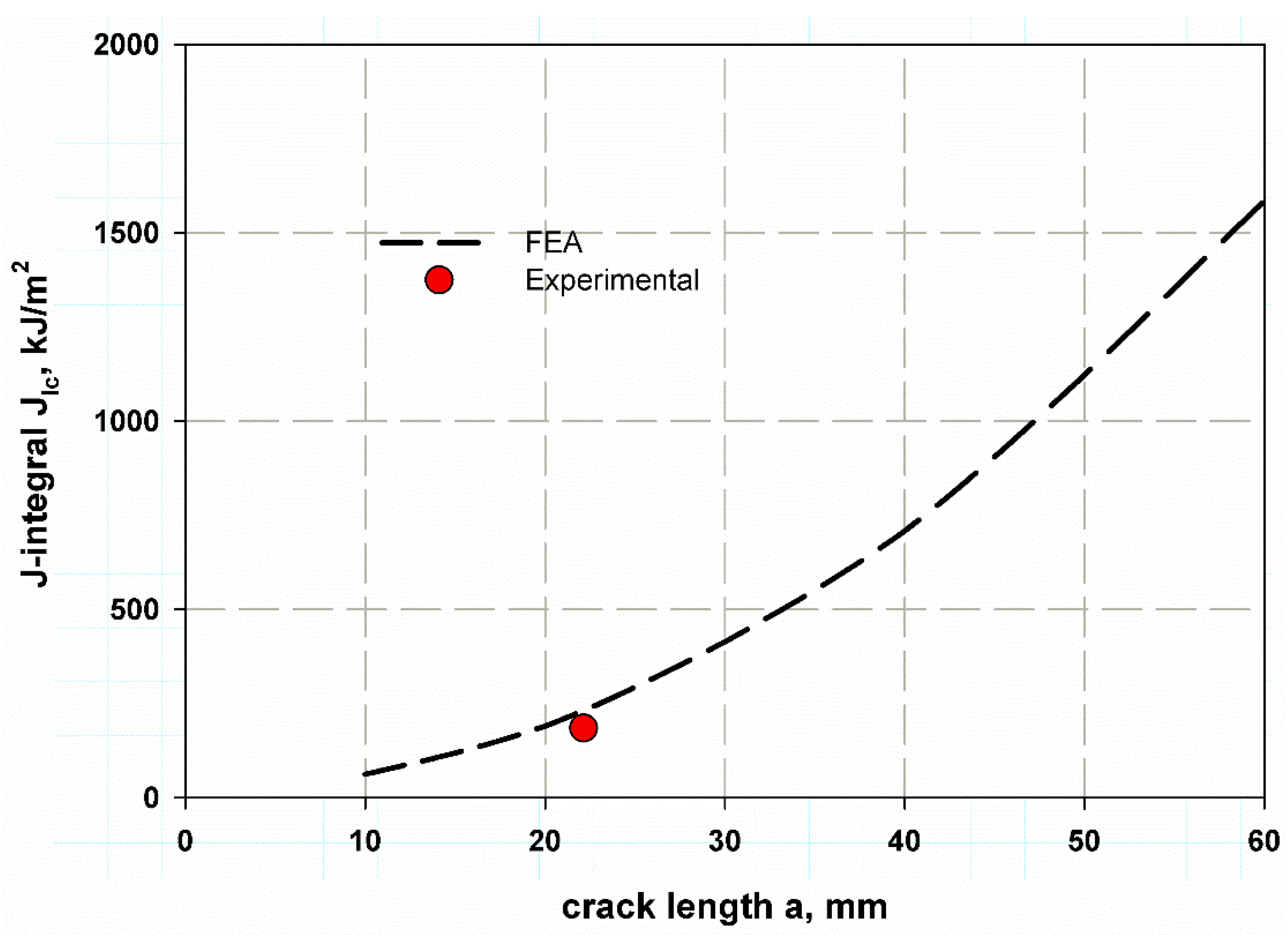
The fitting equation yields very close results from FEM, which can give a wide range of cylinders with different values of (a/t). This idea is similar to what was proposed by Newman [39]. This result may enable the extension of the data below and over the studied range of a crack length 10–60 mm. Figure 13 also can illustrate the effect of cylinder thickness on the stress distribution of Figure 12 also can illustrate the effect of cylinder thickness on the stress distribution through its cross-section. It was observed that increasing thickness meant decreasing the aspect ratio (a/t), which led to lower values of hoop stress. The stress distribution through the thickness was nearly close at a small thickness (see Figure 12). The average J-integral of the five contours is shown in Figure 14. It was predicted using the proposed XFEM for different crack lengths based on the wall thickness of the cylinder. The results of a crack length of 22.5 mm were very close to the compact tension test results. This trend of increasing J-integral with crack length increment is general in composite quasi-brittle materials [56]. The value of experimental fracture toughness is one obtained at critical crack length at the critical crack opening, while the J-integral value is a mathematical curve that passes through the propagation of the crack to infinity of crack length. If the path moves with the experimental value, which is one and constant for the material, then the prediction is considered acceptable. When I need to measure the R-curve of a material through the crack propagation, in this case, the need to obtain more values would be suitable and considered [58,59,60].
The stress intensity factor is shown in Figure 15, and the predicted values were very close to the experimental data reduction using Equation (5) at crack 22.5 mm. The trend again increases with crack increment, as it is assumed that the pipe length to infinity is very long and does not affect the analysis [39].
Table 3 shows the data predicted by Equation (10) of influence coefficients or correction factor based on the fitted data of the FEM for (a/t) ranges 0.2–0.8, and the cracks have rectilinear or square dimensions with movable (nonlinear step) and unmovable cracks (linear step). The large deviation between the data in Reference [61] and the present study is because the present model is for a straight plane crack (rectangular) and cylinder t/R = 0.045.
where C and B are constantly obtained by the well-fitted curve.
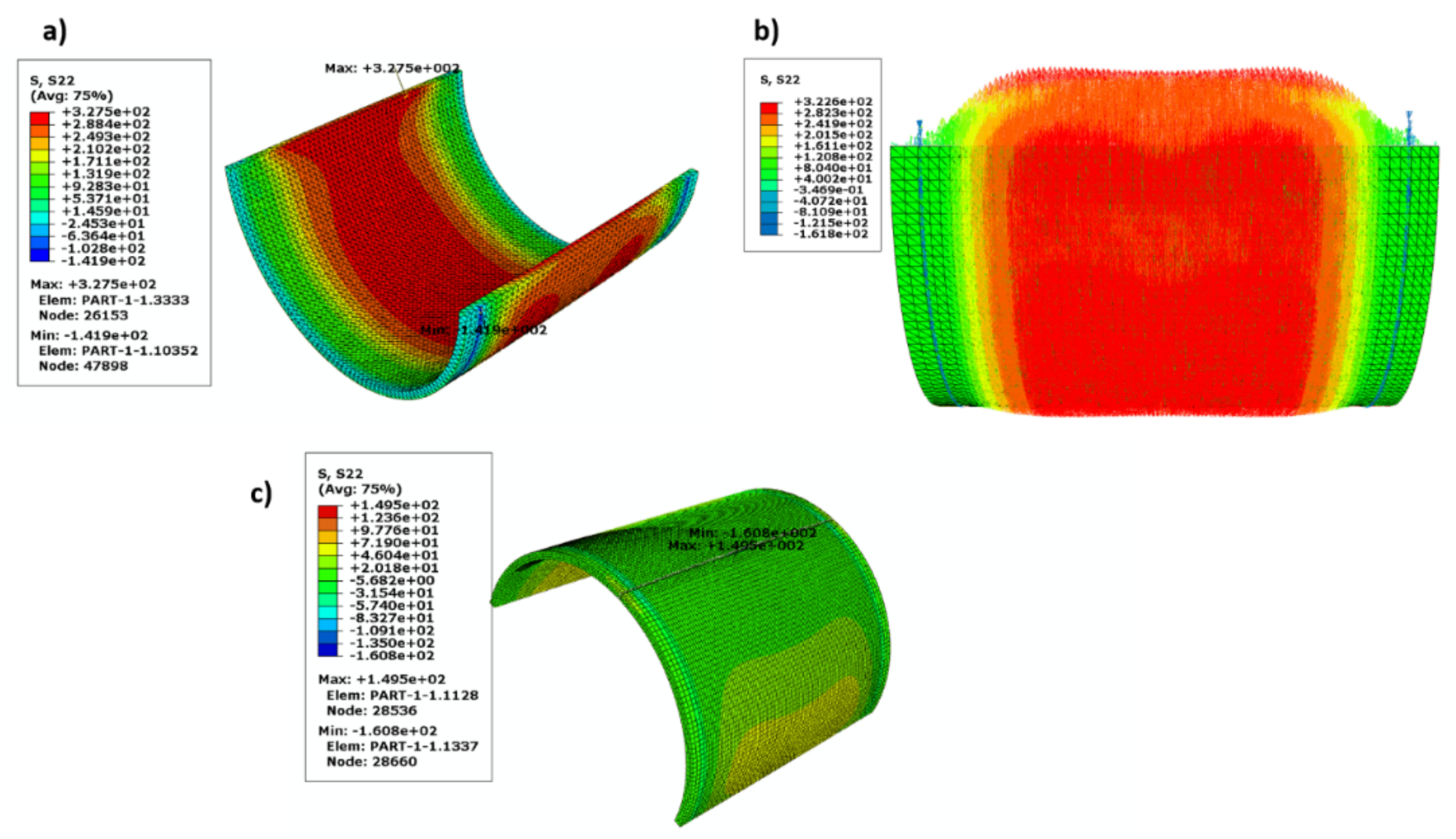
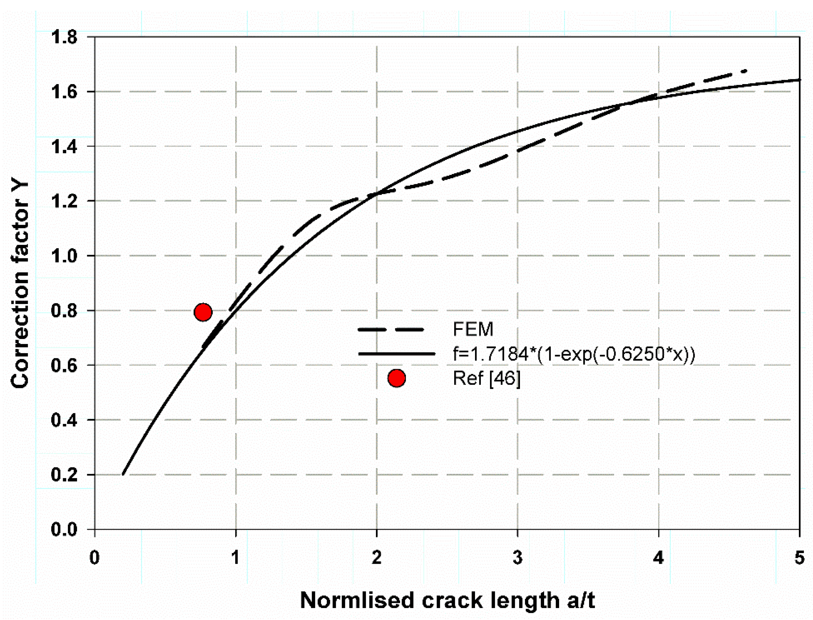
Figure 16 shows the fitted data for the nonlinear FEM with a movable crack, which is a power exponential for a wide range of (a/t) 0.2:5. The results were acceptable and provided reasonable accuracy. This is clearly shown in Figure 17 for a linear FEM with an unmovable crack when compared with the work of [61]. The stress distribution over the wall thickness is shown in Figure 18 using the colour FE contour. The maximum hoop stress was induced through the uncracked specimen’s thickness (Figure 18a,b). However, it was reduced in the crack tips due to the stress concentration around the crack tips (Figure 15).
6. Conclusions
This work has successfully developed a new finite element model (FEM) for predicting the mechanical properties of cracked and neat composite cylinder materials for industrial applications. An expression was extracted to predict the stress intensity factor of a composite cylinder using an XFEM based on the enrichment function. The model yielded reasonably good results. Moreover, the hoop stress induced through the cylinder thickness was assessed for neat and cracked cylinders using XFEM. The stress distribution through the thickness of the cylinder due to internal pressure was demonstrated. It was found that the presence of through-thickness cracks decreases the average hoop stress values (61.2 to 48.5 MPa) through the cylinder’s thickness. The fracture toughness was about 2322 () with a standard deviation 142.5 (), and its corresponding surface release energy was about 153.6 kJ/m2 with a standard deviation 22.53 kJ/m2 which were measured experimentally using a standard compact tension test specimen, which could be used as a fracture toughness standard measurement method for composite cylinder materials. The tensile test results were experimentally measured using standard tensile test specimens of the curved cylinder wall. Overall, taken together with the obtained results and our findings we can conclude that the proposed FEM would have a strong potential for predicting the mechanical properties of composite cylinder materials for industrial applications. Finally, the study is distinguished by fast procedures and few parameters. The model can be applied on many composite pipes reinforced by glass fiber with different shapes and geometry (mat or roving), just it is needed to know the mechanical characteristics of the tested material. Moreover, the numerical model enables the modification of the classical Lame’s Equation (2), and it is applicable for any shape, not just for an elliptical crack as in Newman.
Author Contributions
Conceptualization, M.Y.A., G.T.A.-J. and R.A.; methodology, M.Y.A. and I.A.A.; software, M.Y.A. and G.T.A.-J.; validation, R.A. and G.T.A.-J.; formal analysis, M.Y.A., G.T.A.-J. and I.A.A.; investigation, M.Y.A.; resources, R.A.; writing—original draft preparation, M.Y.A.; writing—review and editing, M.Y.A. and G.T.A.-J.; supervision, G.T.A.-J. and I.A.A.; project administration, M.Y.A. and R.A.; funding acquisition, G.T.A.-J. All authors have read and agreed to the published version of the manuscript.
Funding
The authors would like to thank the Saudi Basic Chemical Industries (SABIC) and the Deanship of Scientific Research at Umm Al-Qura University for supporting this work (grant code: 20-UQU-0070-DSR).
Institutional Review Board Statement
Not applicable.
Informed Consent Statement
Not applicable.
Data Availability Statement
The data presented in this study are available on request from the corresponding author.
Acknowledgments
The authors would like to thank the Saudi Basic Chemical Industries (SABIC) and the Deanship of Scientific Research at Umm Al-Qura University for supporting this work (grant code: 20-UQU-0070-DSR).
Conflicts of Interest
The authors declare no conflict of interest.
Nomenclature
| Critical surface release energy | |
| Critical J-integral | |
| Mode I stress intensity factor | |
| Critical fracture toughness | |
| Internal pressure | |
| Nominal hoop stress= | |
| 5% secant load | |
| Hoop stress | |
| Longitudinal stress | |
| E1, E2 | Young’s modulus in 1 and 2 direction or X, Y |
| G12, G13, G23 | Shear modulus in 1, 2, and 3 direction |
| R | Cylinder radius |
| ν12 | Poisson’s ratio |
| Constants obtained by the well-fitted curve | |
| Shape factor | |
| Equivalent correction factor | |
| Crack length | |
| Constants form well-fitted curve | |
| Cylinder diameter | |
| Correction factor for cracked cylinder | |
| Correction factor for compact tension test specimen | |
| Cylinder thickness | |
| Compact tension test specimen dimension | |
| Equivalent Young’s modulus |
References
- Feng, C.-W. Prediction of Long-Term Creep Behavior of Epoxy Adhesives for Structural Applications. Ph.D. Thesis, Texas A&M University, College Station, TX, USA, 2005. [Google Scholar]
- Abdellah, M.Y.; Hassan, M.K.; Alsoufi, M.S. Fracture and Mechanical Characteristics Degradation of Glass Fiber Reinforced Petroleum epoxy Pipes. J. Manuf. Sci. Prod. 2016, 16, 33–40. [Google Scholar] [CrossRef]
- Goertzen, W.; Kessler, M. Creep behavior of carbon fiber/epoxy matrix composites. Mater. Sci. Eng. A 2006, 421, 217–225. [Google Scholar] [CrossRef]
- Seleem, A.-E.H.A. Failure and Corrosion Analysis of Composite Glass Fiber Reinforced Pipe Lines. Ph.D. Thesis, South Valley University, Qena, Egypt, 2015. [Google Scholar]
- Farshad, M.; Necola, A. Strain corrosion of glass fibre-reinforced plastics pipes. Polym. Test. 2004, 23, 517–521. [Google Scholar] [CrossRef]
- Farshad, M.; Necola, A. Effect of aqueous environment on the long-term behavior of glass fiber-reinforced plastic pipes. Polym. Test. 2004, 23, 163–167. [Google Scholar] [CrossRef]
- Nishizaki, I.; Meiarashi, S. Long-Term Deterioration of GFRP in Water and Moist Environment. J. Compos. Constr. 2002, 6, 21–27. [Google Scholar] [CrossRef]
- Miao, Y.; Chen, H.; Cui, G.; Qi, Y. Preparation of new conductive organic coating for the fiber reinforced polymer composite oil pipe. Surf. Coat. Technol. 2021, 412, 127017. [Google Scholar] [CrossRef]
- Firouzsalari, S.E.; Dizhur, D.; Jayaraman, K.; Ingham, J.M. Bending behaviour of flax fabric-reinforced epoxy pipes. Compos. Part A Appl. Sci. Manuf. 2021, 140, 106179. [Google Scholar] [CrossRef]
- Dong, C. Flexural behaviour of carbon and glass reinforced hybrid composite pipes. Compos. Part C Open Access 2021, 4, 100090. [Google Scholar] [CrossRef]
- Xia, H.; Shi, C.; Wang, J.; Bao, X.; Li, H.; Fu, G. Effects of Thickness and Winding Angle of Reinforcement Laminates on Burst Pressure Capacity of Thermoplastic Composite Pipes. J. Offshore Mech. Arct. Eng. 2021, 143, 051802. [Google Scholar] [CrossRef]
- Xia, H.; Shi, C.; Wang, J.; Bao, X.; Li, H.; Fu, G. Effects of thickness and winding angle of the laminate on internal pressure capacity of thermoplastic composite pipes. J. Offshore Mech. Arct. Eng 2020, 4, 051802. [Google Scholar] [CrossRef]
- Rafiee, R.; Abbasi, F. Numerical and Experimental Analyses of the Hoop Tensile Strength of Filament-Wound Composite Tubes. Mech. Compos. Mater. 2020, 56, 423–436. [Google Scholar] [CrossRef]
- Abdellah, M.; Hassan, M.; Mohamed, A.; Khalil, K. A Novel and Highly Effective Natural Vibration Modal Analysis to Predict Nominal Strength of Open Hole Glass Fiber Reinforced Polymer Composites Structure. Polymers 2021, 13, 1251. [Google Scholar] [CrossRef] [PubMed]
- Stoia, D.I.; Marsavina, L.; Linul, E. Mode I Fracture Toughness of Polyamide and Alumide Samples obtained by Selective Laser Sintering Additive Process. Polymers 2020, 12, 640. [Google Scholar] [CrossRef] [Green Version]
- Antunes, M.B.; Almeida, J.H.S.; Amico, S.C. Curing and seawater aging effects on mechanical and physical properties of glass/epoxy filament wound cylinders. Compos. Commun. 2020, 22, 100517. [Google Scholar] [CrossRef]
- Günöz, A.; Kepir, Y.; Memduh, K. The investigation of hardness and density properties of GFRP composite pipes under seawater conditions. Turk. J. Eng. 2020, 6, 34–39. [Google Scholar]
- Shi, H.; An, Z.; Gao, R. Simulation of Mechanical Behavior and Structural Analysis of Glass Fiber Reinforced Mortar Pipes. Rev. Română Mater. 2020, 50, 198–204. [Google Scholar]
- Nouri, M.; Ashenai-Ghasemi, F.; Rahimi-Sherbaf, G.; Kashyzadeh, K.R. Experimental and Numerical Study of the Static Performance of a Hoop-Wrapped CNG Composite Cylinder Considering Its Variable Wall Thickness and Polymer Liner. Mech. Compos. Mater. 2020, 56, 339–352. [Google Scholar] [CrossRef]
- Sülü, İ.Y.; Temiz, Ş. Mechanical behavior of pressurized composite pipes made of various materials. Mater. Test. 2020, 62, 389–394. [Google Scholar] [CrossRef]
- Sharma, P.; Bera, T.; Semwal, K.; Badhe, R.M.; Sharma, A.; Ramakumar, S.; Neogi, S. Theoretical analysis of design of filament wound type 3 composite cylinder for the storage of compressed hydrogen gas. Int. J. Hydrogen Energy 2020, 45, 25386–25397. [Google Scholar] [CrossRef]
- Atalay, O.; Toktas, I. Notch (stress concentration) factor estimation of a cylinder under internal pressure using different approaches. Mater. Test. 2021, 63, 430–435. [Google Scholar] [CrossRef]
- Rafiee, R.; Rashedi, H.; Rezaee, S. Theoretical study of failure in composite pressure vessels subjected to low-velocity impact and internal pressure. Front. Struct. Civ. Eng. 2020, 14, 1349–1358. [Google Scholar] [CrossRef]
- Alderson, K.; Evans, K. Failure mechanisms during the transverse loading of filament-wound pipes under static and low velocity impact conditions. Composites 1992, 23, 167–173. [Google Scholar] [CrossRef]
- Guades, E.; Aravinthan, T.; Manalo, A.; Islam, M. Experimental investigation on the behaviour of square FRP composite tubes under repeated axial impact. Compos. Struct. 2013, 97, 211–221. [Google Scholar] [CrossRef] [Green Version]
- Gemi, L.; Kara, M.; Avci, A. Low velocity impact response of prestressed functionally graded hybrid pipes. Compos. Part B Eng. 2016, 106, 154–163. [Google Scholar] [CrossRef]
- Velosa, J.; Nunes, J.P.; Antunes, P.; Silva, J.; Marques, A. Development of a new generation of filament wound composite pressure cylinders. Compos. Sci. Technol. 2009, 69, 1348–1353. [Google Scholar] [CrossRef] [Green Version]
- Almeida, J.H.S., Jr.; Ribeiro, M.L.; Tita, V.; Amico, S.C. Damage and failure in carbon/epoxy filament wound composite tubes under external pressure: Experimental and numerical approaches. Mater. Des. 2016, 96, 431–438. [Google Scholar] [CrossRef]
- Huang, Z.; Qian, X.; Su, Z.; Pham, D.C.; Sridhar, N. Experimental investigation and damage simulation of large-scaled filament wound composite pipes. Compos. Part B Eng. 2020, 184, 107639. [Google Scholar] [CrossRef]
- Ahmad, M.G.; Hoa, S. Flexural stiffness of thick walled composite tubes. Compos. Struct. 2016, 149, 125–133. [Google Scholar] [CrossRef]
- Srinivasan, T.; Suresh, G.; Ramu, P.; Vignesh, R.; Harshan, A.V.; Vignesh, K. Effect of hygrothermal ageing on the compressive behavior of glass fiber reinforced IPN composite pipes. Mater. Today Proc. 2021, 45, 1354–1359. [Google Scholar] [CrossRef]
- Shi, X.; Zhang, R.; Ruanab, K.; Maab, T.; Guoab, Y.; Guab, J. Improvement of thermal conductivities and simulation model for glass fabrics reinforced epoxy laminated composites via introducing hetero-structured BNN-30@BNNS fillers. J. Mater. Sci. Technol. 2021, 82, 239–249. [Google Scholar] [CrossRef]
- Zubail, A.; Traidia, A.; Masulli, M.; Vatopoulos, K.; Villette, T.; Taie, I. Carbon and energy footprint of nonmetallic composite pipes in onshore oil and gas flowlines. J. Clean. Prod. 2021, 305, 127150. [Google Scholar] [CrossRef]
- Tang, L.; Zhang, J.; Tang, Y.; Kong, J.; Liu, T.; Gu, J. Polymer matrix wave-transparent composites: A review. J. Mater. Sci. Technol. 2021, 75, 225–251. [Google Scholar] [CrossRef]
- Liu, Z.; Zhang, J.; Tang, Y.; Xu, J.; Ma, H.; Kong, J.; Gu, J. Optimization of PBO fibers/cyanate ester wave-transparent laminated composites via incorporation of a fluoride-containing linear interfacial compatibilizer. Compos. Sci. Technol. 2021, 210, 108838. [Google Scholar] [CrossRef]
- Tang, L.; Zhang, J.; Gu, J. Random copolymer membrane coated PBO fibers with significantly improved interfacial adhesion for PBO fibers/cyanate ester composites. Chin. J. Aeronaut. 2021, 34, 659–668. [Google Scholar] [CrossRef]
- Tang, L.; Dang, J.; He, M.; Li, J.; Kong, J.; Tang, Y.; Gu, J. Preparation and properties of cyanate-based wave-transparent laminated composites reinforced by dopamine/POSS functionalized Kevlar cloth. Compos. Sci. Technol. 2019, 169, 120–126. [Google Scholar] [CrossRef]
- Hearn, E.J. Mechanics of Materials 2: The Mechanics of Elastic and Plastic Deformation of Solids and Structural Materials; Elsevier: Woburn, MA, USA, 1997. [Google Scholar]
- Newman, J., Jr.; Raju, I. Stress-intensity factors for internal surface cracks in cylindrical pressure vessels. J. Press. Vessel. Technol. 1980, 102, 342–346. [Google Scholar] [CrossRef]
- Hearn, E. Simple stress and strain. In Mechanics of Materials 1, 3rd ed.; Elsevier: Amsterdam, The Netherlands, 1997; pp. 1–26. [Google Scholar] [CrossRef]
- Belytschko, T.; Black, T. Elastic crack growth in finite elements with minimal remeshing. Int. J. Numer. Methods Eng. 1999, 45, 601–620. [Google Scholar] [CrossRef]
- Melenk, J.; Babuška, I. The partition of unity finite element method: Basic theory and applications. Comput. Methods Appl. Mech. Eng. 1996, 139, 289–314. [Google Scholar] [CrossRef] [Green Version]
- Datta, D. Introduction to eXtended Finite Element (XFEM) Method. arXiv 2013, arXiv:1308.5208. [Google Scholar]
- Abdellah, M.Y.; Alsoufi, M.S.; Hassan, M.K.; Ghulman, H.A.; Mohamed, A.F. Rozszerzona Analiza Numeryczna Metoda Elementów Skonczonych Efektu Skali W Epoksydowym Kompozycie Z Karbem Wzmocnionym Włóknem Szklanym [Extended Finite Element Numerical Analysis of Scale Effect in Notched Glass Fiber Reinforced Epoxy Composite]. Arch. Mech. Eng. 2015, 62, 217–236. [Google Scholar] [CrossRef] [Green Version]
- Faria, H. Failure Analysis of GRP Pipes Under Compressive Ring Loads. Master’s Thesis, Universidade do Porto, Porto, Portugal, 2005. [Google Scholar]
- Mohammed, Y.; Hassan, M.K.; Hashem, A. Analytical model to predict multiaxial laminate fracture toughness from 0° ply fracture toughness. Polym. Eng. Sci. 2013, 54, 234–238. [Google Scholar] [CrossRef]
- ASTM International. ASTM D3039/D3039M-17. Standard Test Method for Tensile Properties of Polymer Matrix Composite Materials; ASTM International: West Conshohocken, PA, USA, 2017. [Google Scholar]
- ASTM International. D5045-14. Standard Test Methods for Plane-Strain Fracture Toughness and Strain Energy Release Rate of Plastic Materials; Book of Standards; ASTM International: West Conshohocken, PA, USA, 2014; Volume 99, pp. 1–9. [Google Scholar]
- Bažant, Z.P.; Planas, J. Fracture and Size Effect in Concrete and Other Quasibrittle Materials. In Fracture and Size Effect in Concrete and Other Quasibrittle Materials; Informa UK Limited: London, UK, 2019; Volume 16. [Google Scholar]
- Yang, L.; Yang, Y.; Zheng, H. A phase field numerical manifold method for crack propagation in quasi-brittle materials. Eng. Fract. Mech. 2021, 241, 107427. [Google Scholar] [CrossRef]
- Hassan, M.K.; Abdellah, M.Y.; Azabi, S.K.; Marzouk, W. Fracture Toughness of a Novel GLARE Composite Material. Int. J. Eng. Technol. 2015, 15, 36–41. [Google Scholar]
- Hassan, M.K. Characterization of Face Sheet/Core Debonding Strength in Sandwiched Medium Density Fiberboard. Mater. Sci. Appl. 2017, 8, 673–684. [Google Scholar] [CrossRef] [Green Version]
- Khashaba, U. In-plane shear properties of cross-ply composite laminates with different off-axis angles. Compos. Struct. 2004, 65, 167–177. [Google Scholar] [CrossRef]
- D’Antino, T.; Poggi, C. Stress Redistribution in Glass Fibers of G-FRCM Composites. Key Eng. Mater. 2019, 817, 520–527. [Google Scholar] [CrossRef]
- ASTM International. ASTM E399—90(1997). Standard Test Method for Plane-Strain Fracture Toughness of Metallic Materials; ASTM Standards; ASTM International: West Conshohocken, PA, USA, 2005. [Google Scholar]
- Pinho, S.; Robinson, P.; Iannucci, L. Fracture toughness of the tensile and compressive fibre failure modes in laminated composites. Compos. Sci. Technol. 2006, 66, 2069–2079. [Google Scholar] [CrossRef] [Green Version]
- Paris, P.C.; Sih, G.C. Stress Analysis of Cracks. In Fracture Toughness Testing and Its Applications; ASTM International: West Conshohocken, PA, USA, 2009; p. 30. [Google Scholar]
- Khashaba, U. Tensile and flexural properties of randomly oriented gfrp composites. In Proceedings of 1st International Conference on Mechanical Engineering Advanced Technology for Industrial Production; Assiut University: Assiut, Egypt, 1994; Volume 1, pp. 131–143. [Google Scholar]
- Anderson, T.; McHenry, H.; Dawes, M. Elastic-plastic fracture toughness tests with single-edge notched bend specimens. In Elastic-Plastic Fracture Test Methods: The User’s Experience; ASTM International: West Conshohocken, PA, USA, 2008; p. 210. [Google Scholar]
- Soutis, C.; Curtis, P.T.; Fleck, N.A. Compressive failure of notched carbon fibre composites. Proc. R. Soc. A Math. Phys. Sci. 1993, 440, 241–256. [Google Scholar]
- Raju, I.S.; Newman, J., Jr. Stress-intensity factors for internal and external surface cracks in cylindrical vessels. J. Press. Vessel. Technol. 1982, 104, 293–298. [Google Scholar] [CrossRef]
Figure 1.
Crack location through the thickness.
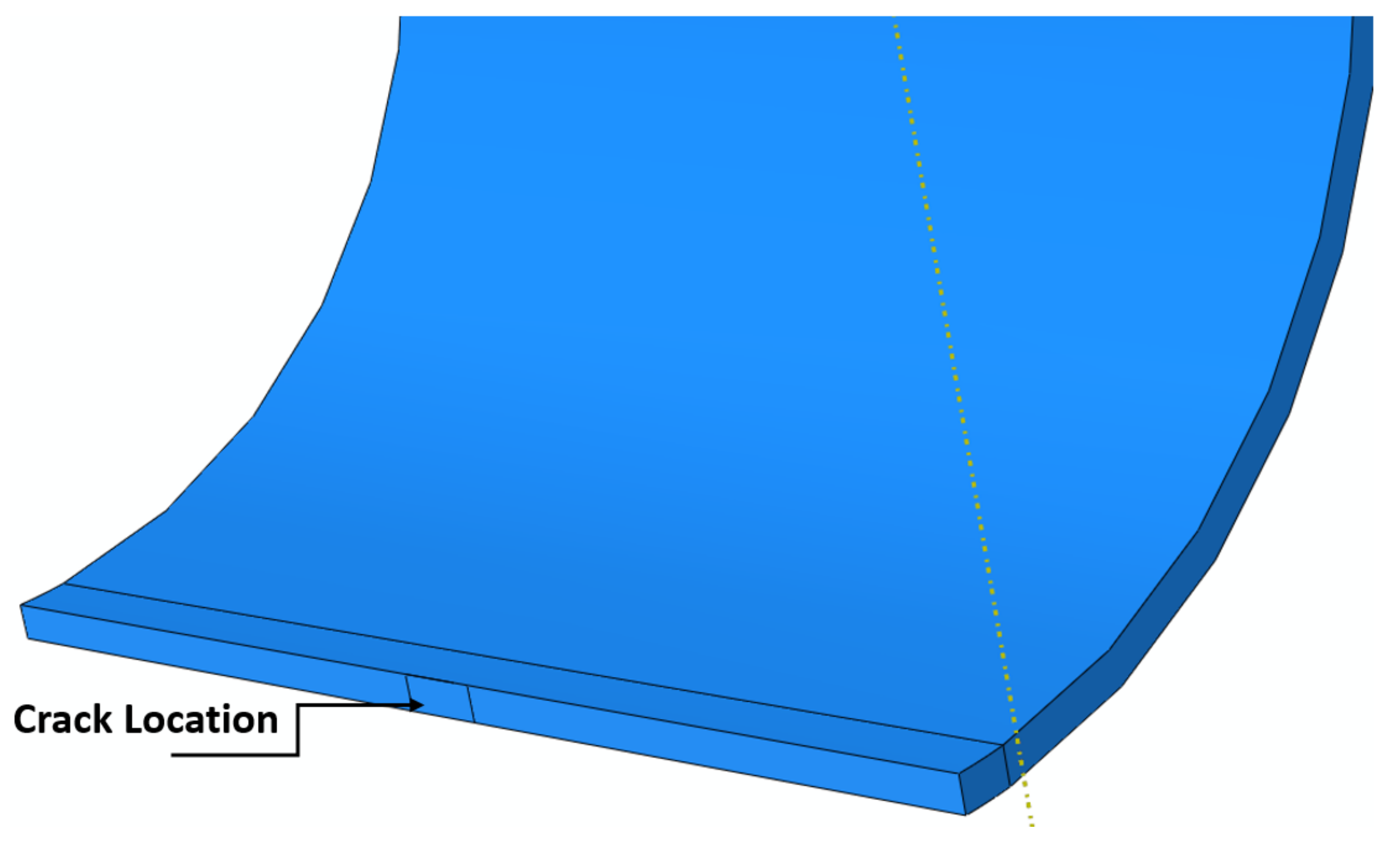
Figure 2.
FE (a) solid domain, (b) boundary condition domain.
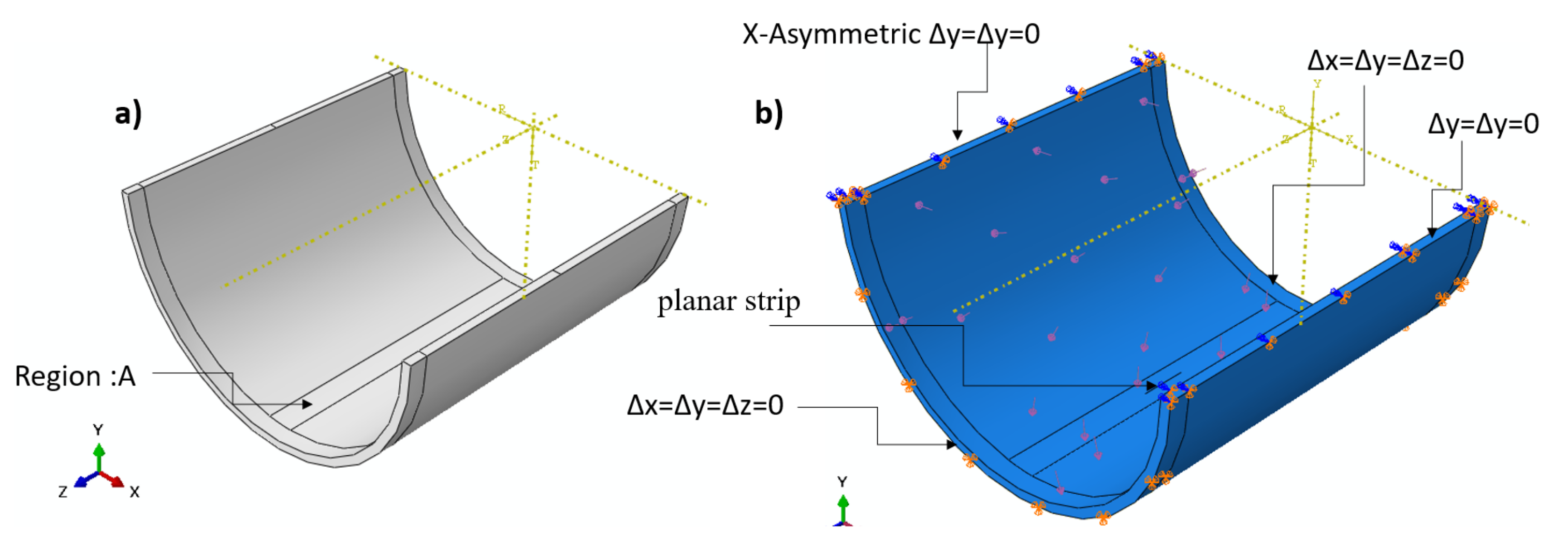
Figure 3.
FE mesh (a) tetrahedron shape (un-notched), (b) hexagonal shape (notched).

Figure 4.
Schematic drawing of GRP cross-section.
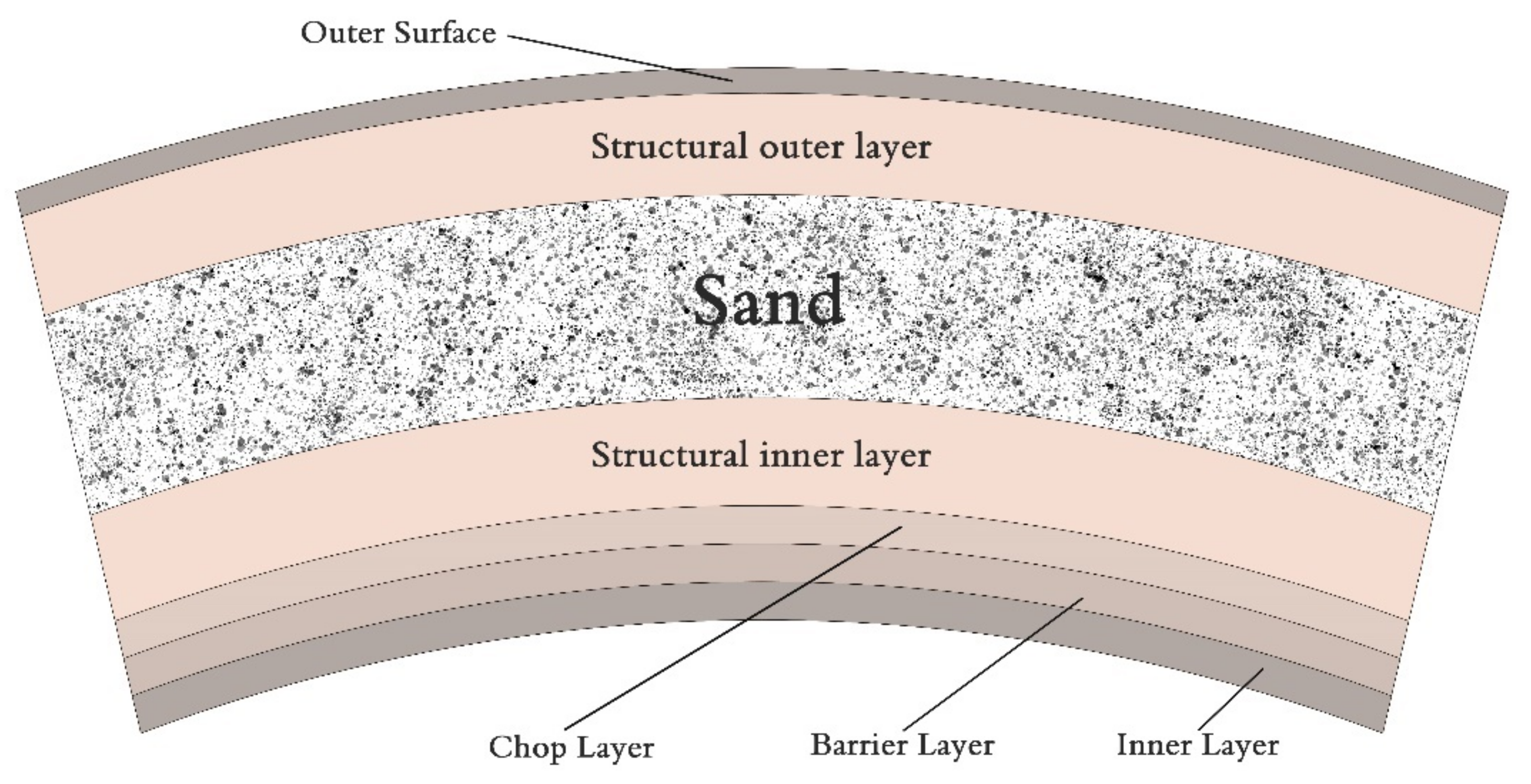
Figure 5.
GRP constitutive contents (a) fiber shape, (b) quartz sand shape and size.
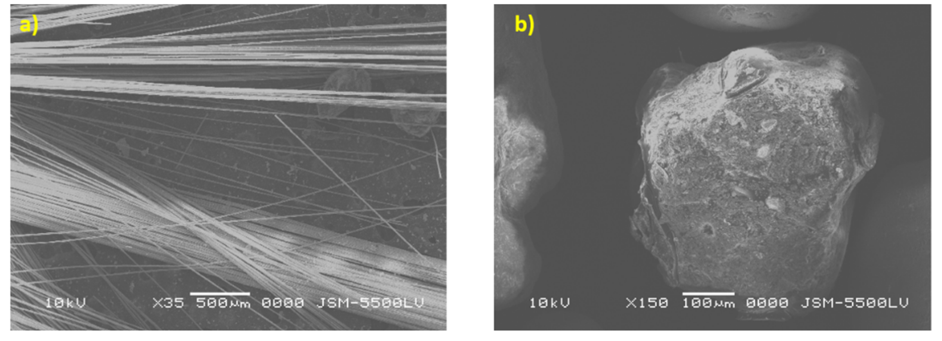
Figure 6.
Tensile test specimen geometry.
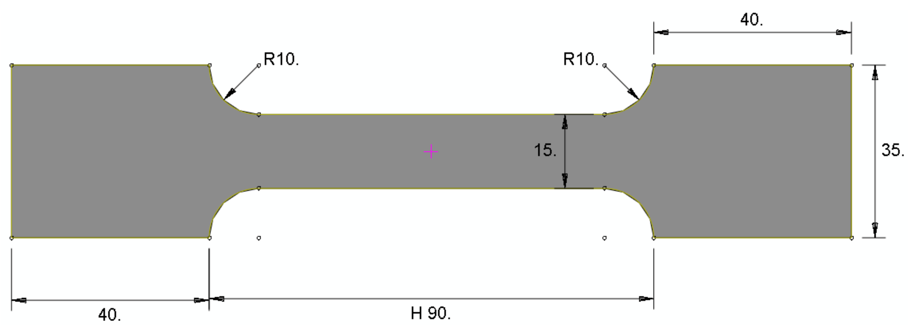
Figure 7.
CT test specimen geometry.
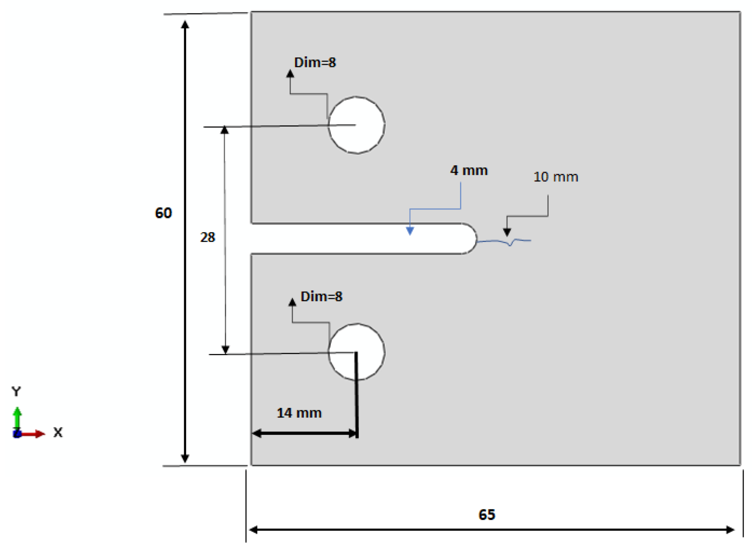
Figure 8.
Stress–strain curve for the tension of GRP pipe material.
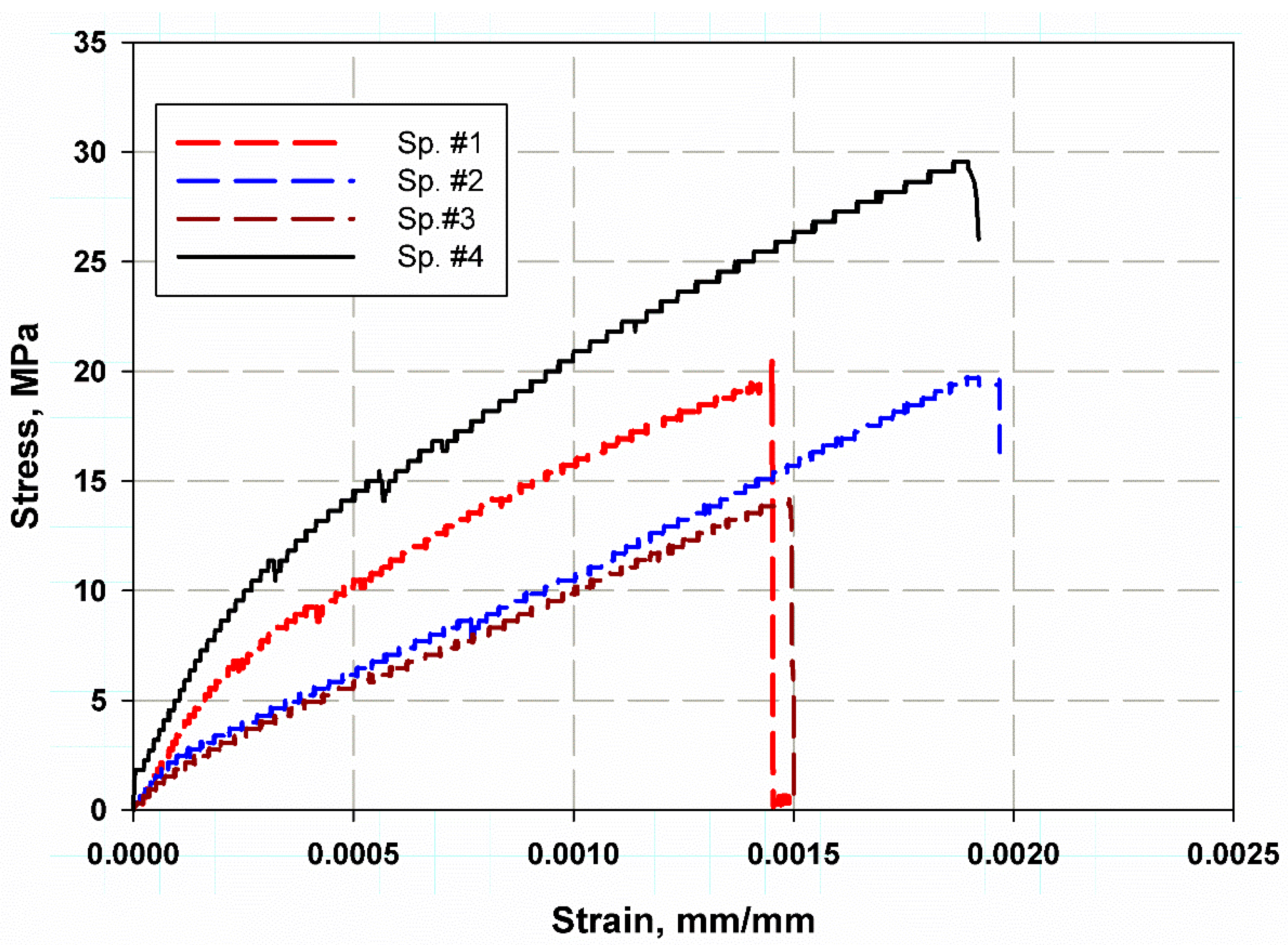
Figure 9.
(a,b) SEM examination of fracture surface in the tension test specimen.
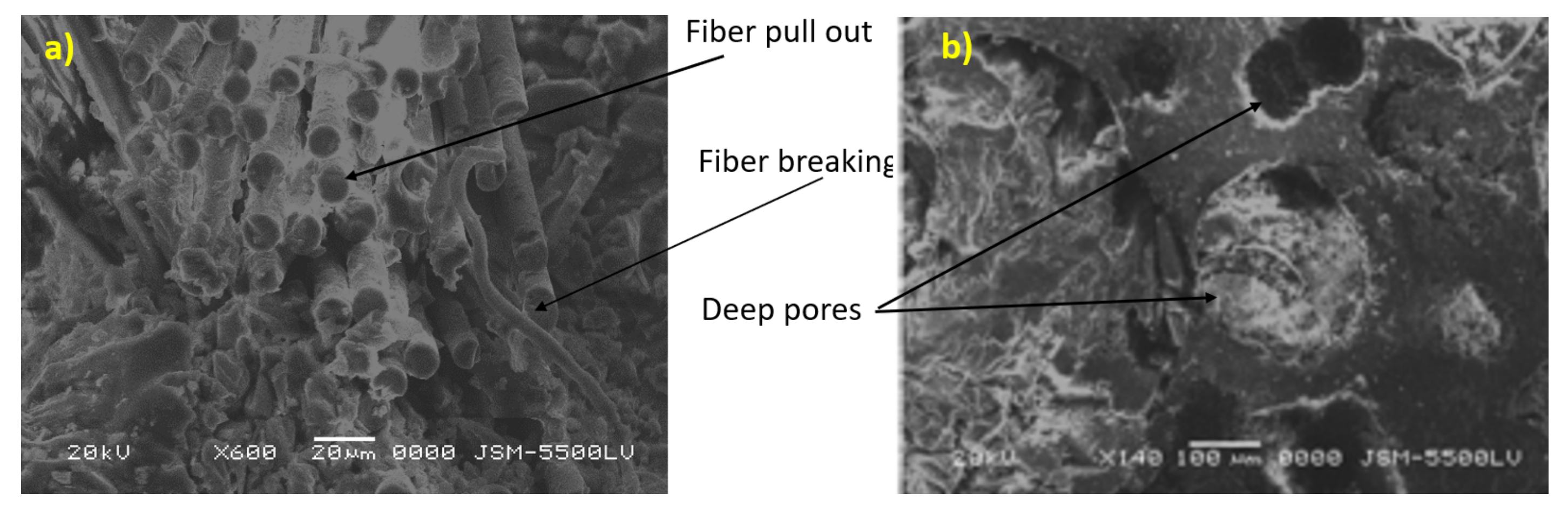
Figure 10.
Load–displacement curve of different compact tension specimens.
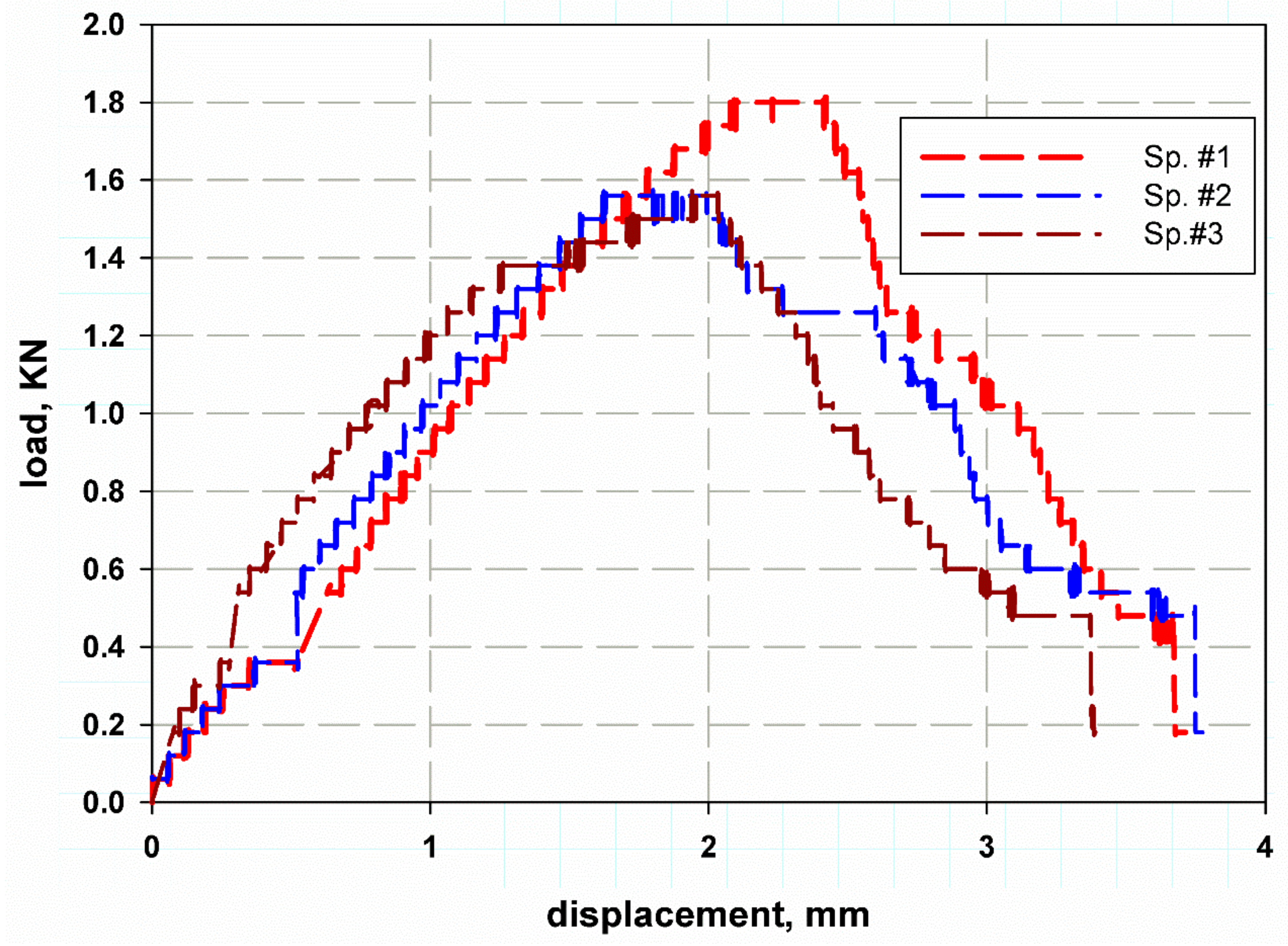
Figure 11.
(a,b) SEM examination of fracture surface in compact tension specimen.

Figure 12.
Hoop stress distribution across the thickness.
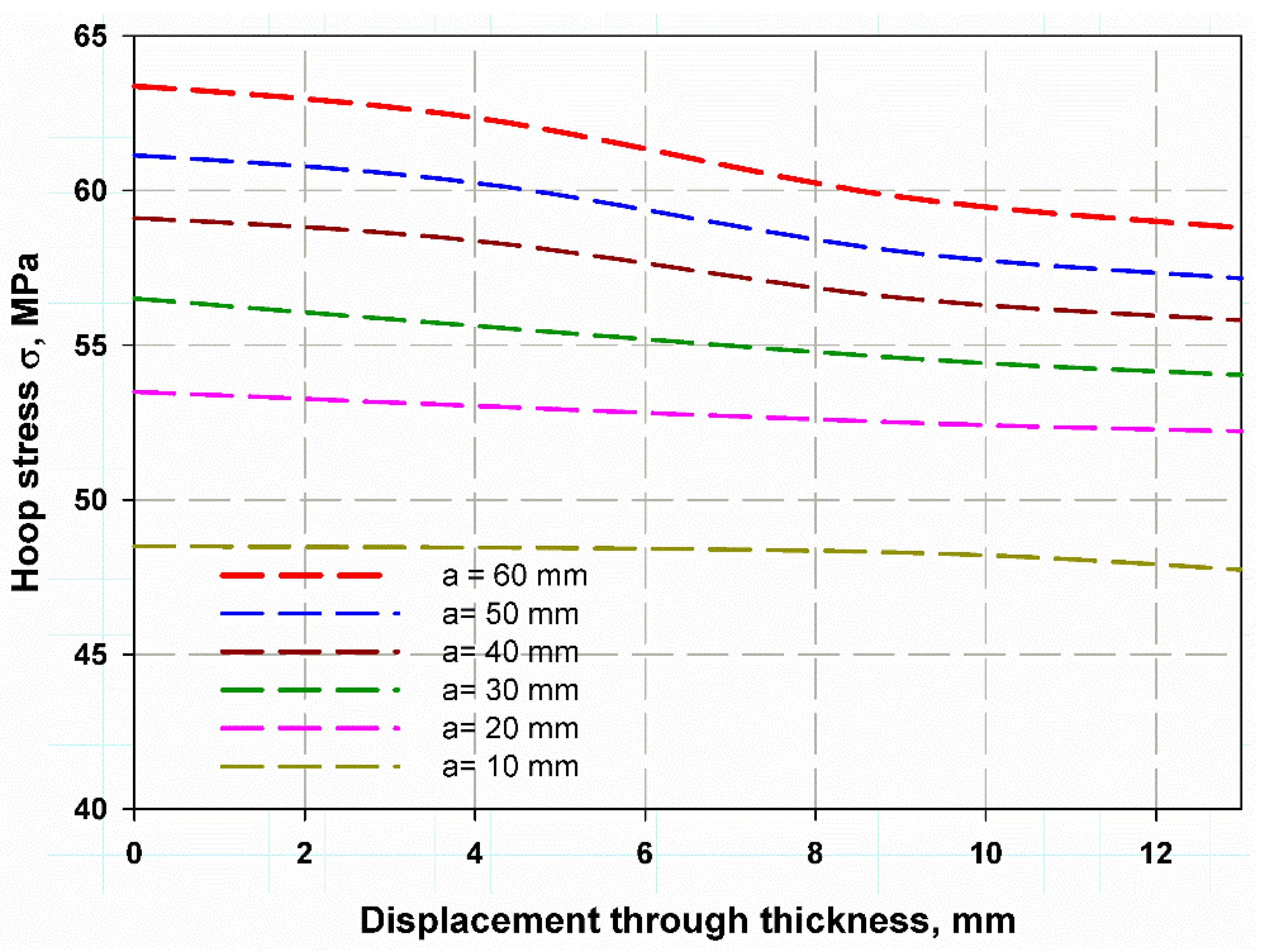
Figure 13.
Nominal hoop stress versus the normalized crack length.
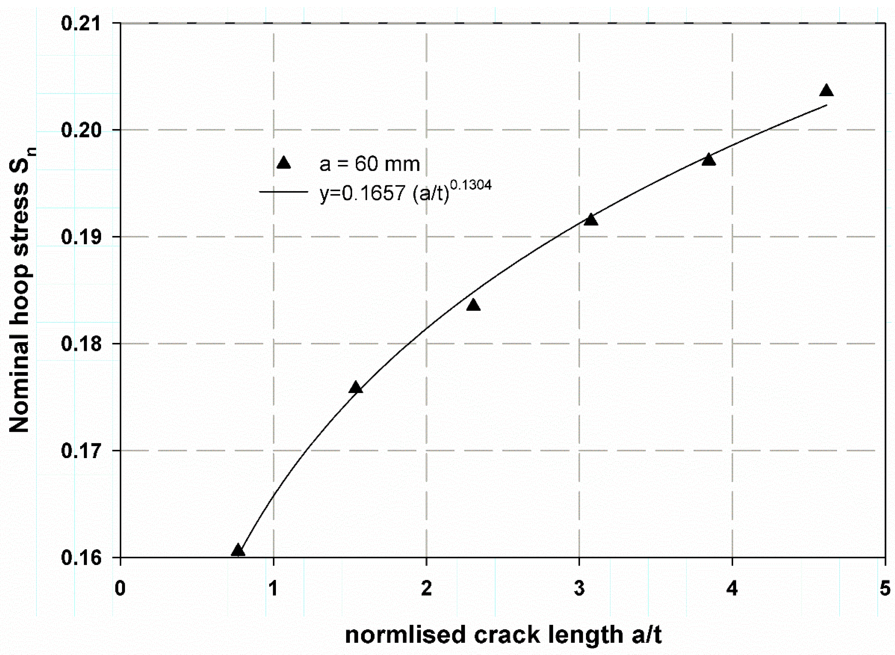
Figure 14.
J-integral prediction using XFEM for through-thickness crack of the composite cylinder.

Figure 15.
Stress intensity factor for thin-walled composite cylinder under internal pressure.
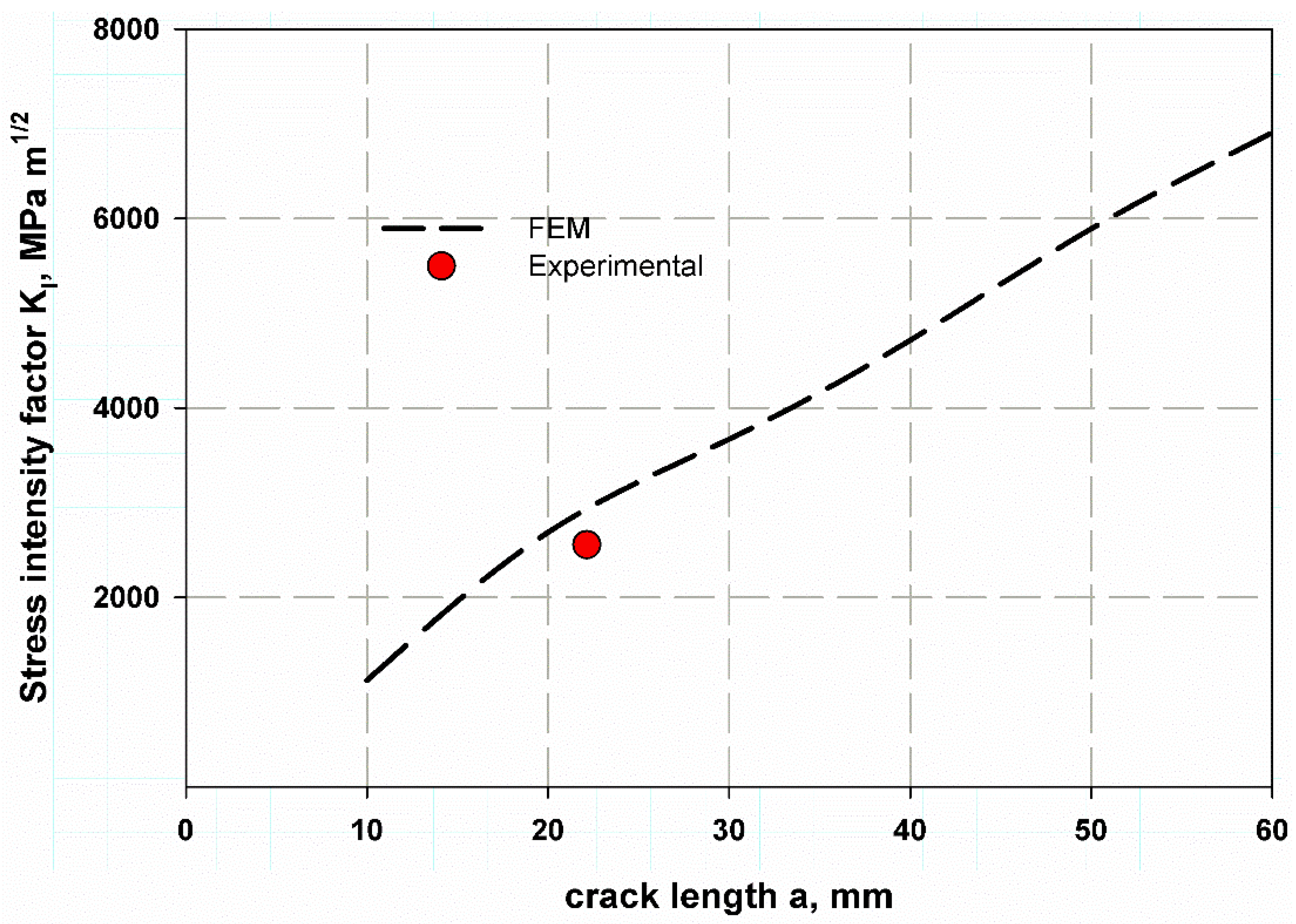
Figure 16.
Correction factor for a movable crack through the thickness of the walled composite cylinder.
Figure 16.
Correction factor for a movable crack through the thickness of the walled composite cylinder.
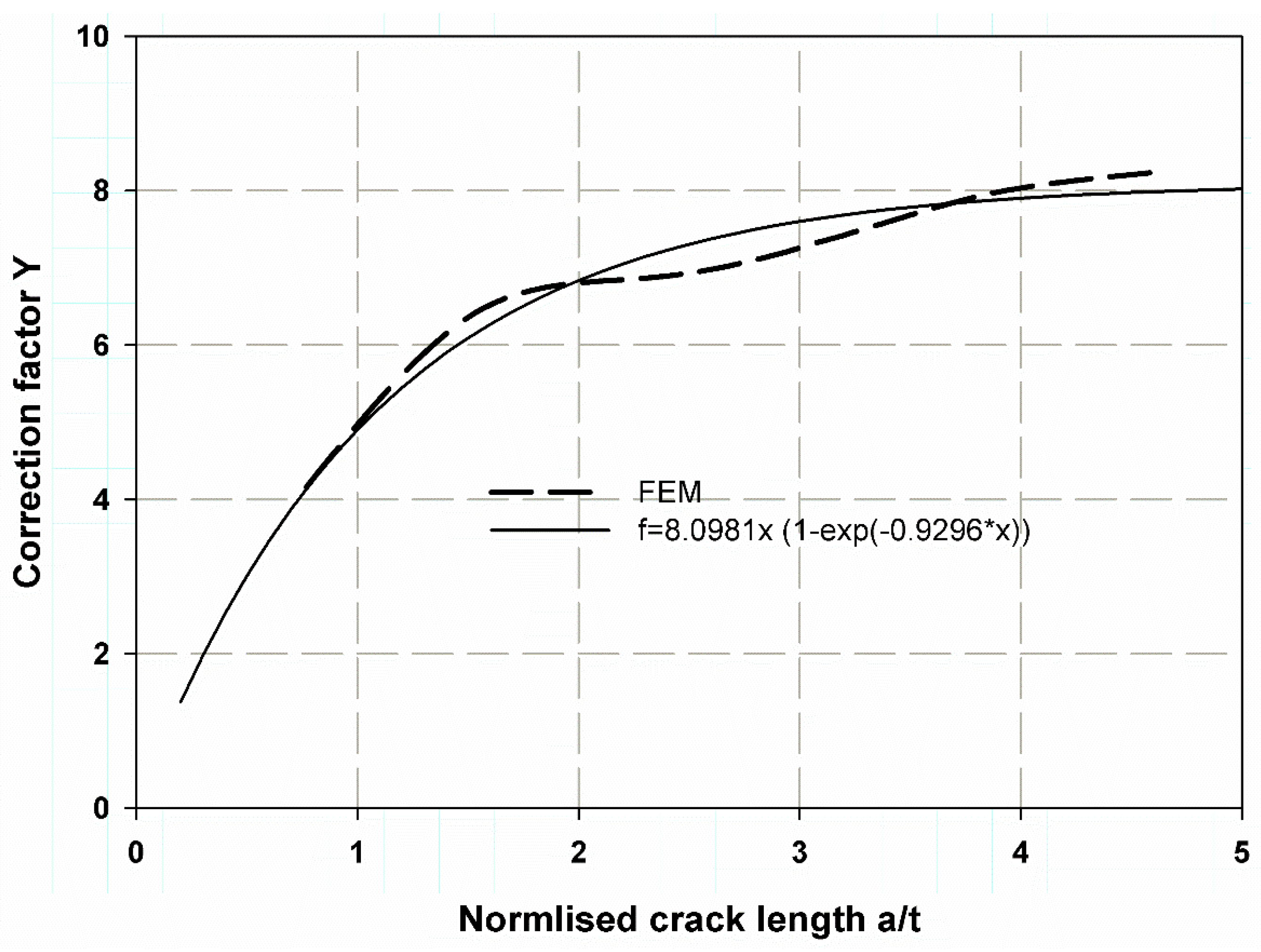
Figure 17.
Correction factor for an unmovable crack through-thickness of walled composite cylinder.

Figure 18.
Hoop stress distribution (a) cylinder (b) cylinder with stress direction, (c) cracked cylinder.
Figure 18.
Hoop stress distribution (a) cylinder (b) cylinder with stress direction, (c) cracked cylinder.

Table 1.
Composition of GFR pipes [2].
Table 1.
Composition of GFR pipes [2].
| Constituents | Average % | Viscosity/cp.25 °C | Thermal Deformation Temperature/°C | Tensile Strength/MPa | Specific Density (g/cm3) |
|---|---|---|---|---|---|
| Thermosetting unsaturated polyester (Matrix) | 30.2% | 400 | 70 | 65 | 1.12 |
| Roving | 11.8 | - | - | 3100–3400 | 2.5 |
| Matt | 13.5 | - | - | ||
| Sand | 44.5 | - | - | - | 2.66 |
Table 2.
Elastic properties of GRP [45].
Table 2.
Elastic properties of GRP [45].
| Properties | E1 (GPa) | E2 (GPa) | ν12 | G12 (GPa) | G13 (GPa) | G23 (GPa) |
|---|---|---|---|---|---|---|
| Value | 100 | 9 | 0.3 | 3.2 | 3.2 | 4 |
Table 3.
Influence coefficients Y for stress intensity factor with linear and nonlinear curve fitting.
Table 3.
Influence coefficients Y for stress intensity factor with linear and nonlinear curve fitting.
| a/t | Y (Nonlinear) | Ref. [61] | % Error | Y (Linear) |
|---|---|---|---|---|
| 0.2 | 0.2019 | 0.197 | 2.43 | 1.3739 |
| 0.4 | 0.3801 | 0.31 | 18.44 | 2.5147 |
| 0.6 | 0.5374 | 0.458 | 14.77 | 3.462 |
| 0.8 | 0.6761 | 0.702 | −3.83 | 4.2486 |
Publisher’s Note: MDPI stays neutral with regard to jurisdictional claims in published maps and institutional affiliations. |
© 2021 by the authors. Licensee MDPI, Basel, Switzerland. This article is an open access article distributed under the terms and conditions of the Creative Commons Attribution (CC BY) license (https://creativecommons.org/licenses/by/4.0/).
Share and Cite
MDPI and ACS Style
Abdellah, M.Y.; Alfattani, R.; Alnaser, I.A.; Abdel-Jaber, G.T. Stress Distribution and Fracture Toughness of Underground Reinforced Plastic Pipe Composite. Polymers 2021, 13, 2194. https://doi.org/10.3390/polym13132194
AMA Style
Abdellah MY, Alfattani R, Alnaser IA, Abdel-Jaber GT. Stress Distribution and Fracture Toughness of Underground Reinforced Plastic Pipe Composite. Polymers. 2021; 13(13):2194. https://doi.org/10.3390/polym13132194
Chicago/Turabian StyleAbdellah, Mohammed Y., Rami Alfattani, Ibrahim A. Alnaser, and G. T. Abdel-Jaber. 2021. "Stress Distribution and Fracture Toughness of Underground Reinforced Plastic Pipe Composite" Polymers 13, no. 13: 2194. https://doi.org/10.3390/polym13132194
Note that from the first issue of 2016, this journal uses article numbers instead of page numbers. See further details here.