Article

Fabrication of Highly Oriented Cylindrical Polyacrylonitrile, Poly(lactide-co-glycolide), Polycaprolactone and Poly(vinyl acetate) Nanofibers for Vascular Graft Applications

1
Electrospun Materials & Polymeric Membranes Research Group (EMPMRG), National Textile University, Sheikhupura Road, Faisalabad 37610, Pakistan
2
Department of Mechanical Engineering, National University of Singapore, 9 Engineering Drive 1, Singapore 117576, Singapore
*
Author to whom correspondence should be addressed.
Polymers 2021, 13(13), 2075; https://doi.org/10.3390/polym13132075
Submission received: 17 May 2021 / Revised: 22 June 2021 / Accepted: 22 June 2021 / Published: 24 June 2021
(This article belongs to the Special Issue Structure-Property Relationships in Polymer Fibers)

Abstract

:
Small-diameter vascular grafts fabricated from synthetic polymers have found limited applications so far in vascular surgeries, owing to their poor mechanical properties. In this study, cylindrical nanofibrous structures of highly oriented nanofibers made from polyacrylonitrile, poly (lactide-co-glycolide) (PLGA), polycaprolactone (PCL) and poly(vinyl acetate) (PVAc) were investigated. Cylindrical collectors with alternate conductive and non-conductive segments were used to obtain highly oriented nanofibrous structures at the same time with better mechanical properties. The surface morphology (orientation), mechanical properties and suture retention of the nanofibrous structures were characterized using SEM, mechanical tester and universal testing machine, respectively. The PLGA nanofibrous cylindrical structure exhibited excellent properties (tensile strength of 9.1 ± 0.6 MPa, suture retention strength of 27N and burst pressure of 350 ± 50 mmHg) when compared to other polymers. Moreover, the PLGA grafts showed good porosity and elongation values, that could be potentially used for vascular graft applications. The combination of PLGA nanofibers with extracellular vesicles (EVs) will be explored as a potential vascular graft in future.

1. Introduction

Cardio vascular diseases (CVD) are increasing day by day and becoming one of the primary causes of annual deaths around the world [1]. Coronary artery (CA) disease is one of the most noticeable forms of cardiovascular diseases [2], whereas the main cause of CVD is the blocking of blood vessels, limiting blood supply to vital organs [3]. Current treatment choices depend on surgical revascularization by implantation of a graft to bypass the blockage. [4] Surgeons usually use the saphenous vein during CA surgery; though, removal of the vein becomes a cause of major indisposition at donor site [5]. Furthermore, limited availability of autologous grafts also limits their application. Thus, a feasible option for the bypass of blocked small diameter blood vessels is highly desirable. Tissue engineered vascular grafts have made outstanding progress [6,7]. Tissue engineering (TE) has been used for surgery of tissues and organs [8]. In TE, a three dimensional (3D) scaffold has been used for repairing the defected/damaged blood vessels, which mimic the structure of extracellular matrix (ECM) of blood vessels [9]. Even though, various materials have been explored to design the nanoscale features of scaffolds, but polymeric nanofibers have been reported as one of the best options to mimic the native structure of ECM [10,11]. Even though different techniques can be used to fabricate nanofibers, viz phase separation [12,13], drawing [14], template synthesis [15,16,17], self-assembly [18,19] and electrospinning [20,21], but electrospinning has gained a lot of importance, due to its ability to fabricate scaffolds that mimic the well-ordered architecture of native ECM of tissues [22]. It is a smart choice, being simple, cost effective and environmentally friendly [23]. Furthermore, it can fabricate nanowebs in specific structures with controlled orientation and diameter [24,25].
In recent years, nanofibers have been used for various biomedical applications [26,27]. Even though randomly collected nanofibers can be used in various fields of TE, but in some applications such as vascular grafts, it is essential that the nanofibers should also be axially oriented [28], as the orientation of the nanofibers influences the mechanical properties, cell growth and relevant cell functions [29]. Even though a wide range of electrospinning setups have been developed to acquire oriented nanofibers, rotating drum/disk collectors are some of the most widely used to acquire oriented fibers. The degree of alignment within the nanofibers can be controlled by varying the speed of the rotating drum/disk collector. At low speed, randomly oriented nanofibers are collected. However, with increasing the speed, the degree of fiber orientation improves.
Researchers have investigated use of various types of collectors for nanofibers orientation in a specific direction, yet limited work has been accomplished in the field of orienting the nanofibers in cylindrical shape for vascular grafts. In one of the studies, round collectors with conductive parts separated by insulating gaps were used to acquire orientated nanofibers in the direction of electric field lines in the gap between the two conductive parts. However, this was not successful as the insulating gap was not high enough to achieve the orientation. As the gap increased, the influence of electric field lines on the nanofibers was reduced and control on fiber orientation was also decreased [30,31]. In another study, Teflon rod was used between the metallic plates, but nanofibers orientation was poor, due to high flow rate and low rotational speed of collectors. Later, it was found that significantly high rotational speed was necessary to initiate the process of fiber stretching and thereby fiber orientation. Various researchers have also worked on the orientation of nanofibers, by using a rotating disk of having an insulating tube on the collector [32,33]. However, when the nanofibers layers were increased on the rotating collector, the influence of electrostatic forces was reduced and formation of fiber orientation was affected [34]. Even though, variety of innovative techniques have been introduced to acquire the nanofibers oriented in a specific direction, but it is challenging not only to form better oriented fibers, but also to explore them for vascular graft applications due to their insufficient mechanical strength. This work is aimed to overcome the previous drawbacks by using novel collectors of having alternate conductive and non-conductive segments. We have used a multi-segmented stand- alone collector, in which the lengths of segments have been optimized after several experiments [35,36] to achieve highly oriented nanofibers from four different polymers viz polyacrylonitrile (PAN), poly(lactide-co-glycolide) (PLGA), polycaprolactone (PCL) and poly(vinyl acetate) (PVAc). PAN was selected due to its low cost, non-toxicity, high strength and high modulus of elasticity, and has been used in many medical applications [37,38,39,40,41]. PLGA has good mechanical properties and biodegradability [42], PCL has good biomechanical properties and cell compatibility [43], PVAc also has good biocompatibility [44] and has been used in vascular grafts applications. The overall aim of the study was to find the polymer with best properties of mechanical strength, burst pressure and suture retention strength, that could be used in future for vascular grafts applications.

2. Materials and Methods

Four different polymers, viz., PAN (Mw: 150,000 g/mol), PLGA (Mw: 60,000 g/mol), PCL (Mw: 80,000 g/mol) and PVA (Mw: 500,000 g/mol) were purchased from Sigma Aldrich (St. Louis, MO, USA). Solvents such as N,N-dimethyl formamide and 1, 1, 1, 3, 3, 3-Hexafluoro-2-propanol (≥99%) were supplied by Sigma Aldrich (St. Louis, MO, USA). All the polymer solutions were prepared separately by adding the required amount of polymer and the solvent into a flask with a magnetic stirring for 24 h.

2.1. Electrospinning

The electrospinning of each polymer solution was accomplished separately using Fluidnatek electrospinning set-up, and cylindrical collectors (300 mm length × 5 mm dia.), manufactured in-house, comprising two parts: conductive part (CP) (brass) and non-conductive part (NCP) (Teflon) as depicted in Figure 1. The electrospinning parameters were kept the same for all the polymer solutions, i.e., polymer concentration 11 wt %, electrospinning needle gauge size of 21, voltage 12 KV, needle-to-collector distance 14 cm, solution flow rate 150 μL/h, and collector rotational speed of 100 rpm. Groove depth of the collector was kept at 2 mm. All of the parameters were selected from the previously reported procedure.
Axially aligned scaffolds were collected on the rotating collectors. When two conducting parts of the collector, separated by non-conducting parts, are used, the fiber jet will deposit on the non-conducting part in between the conducting parts and a horizontally aligned array of nanofibers will be produced. The electric field lines in the non-conducting part near the conducting part are drawn towards the conducting part. The fiber jet stretches across the non-conducting part as the field lines are attracted towards the conducting part. This in turn orients the nanofibers on the non-conducting part of the collector. Due to presence of charge on the nanofibers, mutual repulsion between the deposited nanofibers will enhance the parallel and relatively even distribution of nanofibers. This process is repeated in all the non-conducting parts surrounded by the conducting parts and thus an array of longitudinally oriented nanofibers could be collected on the entire collector. After spinning, the electrospun vascular grafts were removed from the collector and stored in a desiccator for further testing and characterizations. Preparation and testing of scaffolds are shown in Figure 1.

2.2. Scanning Electron Microscopy

Samples were coated with a thin layer of gold to make nanofibers conductive. Then a Field emission scanning electron microscope was used to determine the surface morphology and diameter of the nanofibers at an accelerating voltage of 100 KV and 50 KV. The Java image processing software [Image J 1.52] was used to measure the diameter of the nanofibers (n = 20). The orientation of nanofibers was quantified by using orientation J, a plugin for image J 1.52 software. SEM micrographs of the region of interest (ROI) were used to find out the orientation values. Samples having high orientation values (aligned nanofibers) and low orientation values (not-aligned nanofibers) (Figure 2) were selected for further testing.

2.3. Thickness

Thickness of the electrospun graft samples was measured using a digital caliper on glass slides (Figure 1c). Dimension of each glass slide was 3ʺ × 1ʺ × 1ʺ. Samples were placed between the slides, and thickness was measured according to D 6988-13 standard test method. Each sample was measured from the center, on the right and on the left. The average of these three measurements taken from millimeters was recorded as the thickness of samples. For porosity measurement, the samples were accurately cut about 1cm2 size and weighted to determine apparent density. The porosity of the nanofibers was calculated using the formula given below:
[ 1 ( A p p a r e n t   d e n s i t y   o f   f i b e r o u s   s t r i p ) B u l k   d e n s i t y   o f   P o l y m e r   ] × 100
The bulk densities of PAN, PCL, PVA and PLGA were taken as 0.36 g/cm3, 1.14 g/cm3, 1.19 g/cm3 and 0.75 g/cm3, respectively.

2.4. Mechanical Properties

Mechanical properties of longitudinally aligned vascular grafts were determined by using a universal testing machine (UTM) according to a standard test method (ASTM D 882-01). The samples were cut into 50 mm length and 5 mm width. Load deformation values were recorded at 10 mm/min speed and 20 mm gauge length, using 100 N load cell at a constant speed of 0.1 mm/s.

2.5. Suture Retention Test

Suture retention test was performed on the universal testing machine (UTM) with a load cell of 100 N. For determining suture retention strength, the vascular grafts were cut into strips having dimension of 40 mm × 5 mm. A Prolene suture 2-0 was passed through the strip and surgical knot was achieved 2 mm from the edge of the sample. At one side of the machine, an electrospun strip was clamped and on the other side, the suture was clamped. Then for testing, suture was pulled at a rate of 50 mm/min until it tore out from the strip. The force required to pull the suture was recorded as a suture retention strength.

2.6. Burst Pressure

For burst pressure measurement, 5 mm diameter cylindrical grafts were taken (n = 5). The cylindrical graft was clamped on both sides in a glass chamber at 37 °C. The flow rate was adjusted in the range of 3–6 mL/min while the pressure was adjusted between 18–75 mmHg. In order to determine the blood pressure, the initial pressure was increased, keeping the flow rate the same. For the determination of burst pressure, the pressure was increased until the sample showed complete burst. The highest pressure measured before rupture was considered as burst strength.

3. Results and Discussions

3.1. Surface Morphology and Fiber Orientation and Fiber Diameter

SEM images of not-aligned and aligned scaffolds are shown in Figure 2.
No signs of beads and entanglement of nanofiber were observed in the SEM images. The orientation values of aligned scaffolds were found to be PAN: 89 ± 1.58 degree, PLGA: 88 ± 1.67 degree, PCL: 85 ± 1.58 degree, and PVA: 83 ± 1.3 degree. The orientation values of not-aligned scaffolds were found to be PAN: 25 ± 1.58 degree, PLGA: 24 ± 1.56 degree, PCL: 21 ± 1.26 degree and PVA: 23 ± 1.14 degree. Directional analysis confirmed the alignment of nanofibers in the scaffolds. For not-aligned scaffolds, no proper fiber direction was predominant, while in the aligned scaffolds, a prominent direction was observed and a peak was formed. In the cases of not- aligned scaffolds, the histogram is wider while in the cases of aligned scaffolds, the histogram is narrower, which shows the orientation of fibers is in the same single direction. The average diameters of the nanofibers in aligned scaffolds were found to be, PAN: 159 ± 7 nm, PLGA: 378 ± 20 nm, PCL: 327 ± 25 nm and PVA: 451 ± 40 nm. The average diameters of nanofibers in not-aligned scaffolds were found to be PAN: 162 ± 10 nm, PLGA: 379 ± 20 nm, PCL: 329 ± 30 nm and PVA: 452 ± 30 nm. When we compared the morphology of these nanofibers, it was found that both PLGA and PCL have comparatively rougher exterior morphology (Figure 2A,A′,C,C′ than other samples (Figure 2B,B′ and Figure 2D,D′, and the latter reveals smooth morphology. Figure 2B shows the histograms of diameter distributions of nanofibers at different polymer concentration, conductive segment length (CSL) and non- conductive segment length (NSL). It can be noted that distribution of nanofibers diameters varies for aligned and not-aligned nanofibers.

3.2. Porosity

The porosity of scaffolds was calculated. It was observed that the porosities of non- aligned scaffolds were 93%, 95%, 92% and 94% for PAN, PLGA, PCL and PVA, respectively, while the porosities of aligned scaffolds were 85%, 87%, 78% and 86%, respectively. As shown in Figure 2, small and narrow pores are visible on aligned scaffolds, whereas large pores are visible in the case of not- aligned nanofibers. The aligned scaffolds structures give a denser structure and lower porosity than not-aligned scaffolds [45].

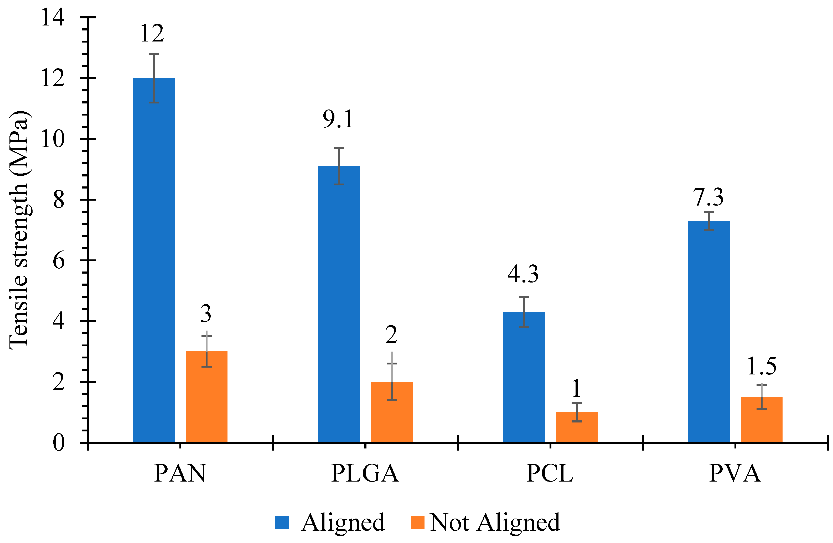
3.3. Tensile Strength

The tensile strength of the scaffolds is shown in Figure 3. For the random electrospun grafts, two clamps of the tensile machine may grip both ends of individual electrospun fibers. Therefore, the stress by the tensile machine is exerted on the individual fiber during the test and then weaker fibers start to break one by one. On the other hand, for the aligned electrospun grafts, the clamp of the tensile machine may grab only one end of the fibers and these fibers are connected with other fibers. Therefore, when the machine stretches the electrospun grafts, the stress is exerted on the fiber networks, rather than individual fibers. During the test, it seems that rearrangement of the fiber networks happens, resulting in the elongation of electrospun grafts. Hence more force is needed to break the grafts.
It was revealed that tensile strength values were varied for both aligned and not-aligned grafts. In the cases of aligned scaffolds, the PAN scaffolds had the highest mechanical strength of 12 ± 0.8 MPa, while the PCL scaffold had the lowest mechanical strength of 4.3 ± 0.5 MPa. Tensile strength values of PLGA and PVA were 9.1 ± 0.6 and 7.3 ± 0.3 MPa, respectively. Tensile strength values for not-aligned scaffolds were 3 ± 0.21, 2 ± 0.15, 1 ± 0.16 and 1.5 ± 0.14 MPa for PAN, PLGA, PCL and PVA, respectively. It was observed that tensile strength values for aligned scaffolds were greater than that of not-aligned scaffolds. The increase in tensile strength of aligned scaffolds is due to the dense structure of aligned scaffolds. Moreover during tensile loading, fibers that are aligned in the direction of loading experience the stretching force hence show resistance against force [45]. Similar observation of aligned scaffolds with enhanced mechanical properties than not-aligned scaffolds was already reported by Neethu Mohan et al. [46].
A comparison of stress strain behavior for aligned scaffolds and not-aligned scaffolds is displayed in Figure 4.
PLGA showed the highest strain (elongation) of 183% at breaking point with a tensile strength of 9.1 MPa. Similarly, the elongation values at break of PAN, PCL and PVA were 29%, 53% and 107%, respectively. While the tensile strength values for not-aligned scaffolds were comparatively lower and elongation at break values were also low, i.e., 120%, 50%, 70% and 25% for PLGA, PVA, PCL and PAN, respectively. It has been reported that femoral arteries show ultimate stress of 1–2 MPa and elongation at break values of 60–80% [47,48]. In the cases of PLGA and PVA scaffolds, they had good mechanical properties, which can satisfy the mechanical properties of artificial vascular grafts. On the other hand, PAN and PCL showed good stress values, but elongation values at break were low.

3.4. Suture Retention Strength
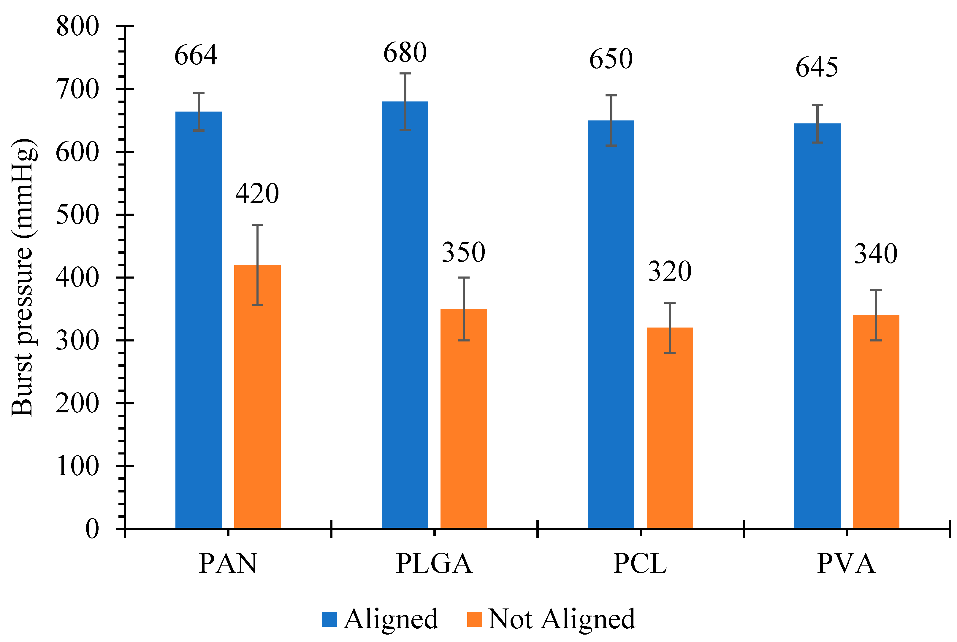
Suture retention strength values for aligned and not-aligned scaffolds are displayed in Figure 5.
In each graft type, five samples were analyzed and mean values of suture retention strength were recorded. In the cases of aligned scaffolds, PLGA had the highest suture retention strength with a value of 27 ± 2 N, whereas PVA had the lowest suture retention strength of 14 ± 0.5 N. Suture retention strength values of aligned PCL and PAN were 23 ± 1.3 N and 25 ± 0.5 N, respectively. The suture retention strength values for not- aligned scaffolds such as PAN, PLGA, PCL and PVA were 15 ± 1 N, 17 ± 1.5 N, 12 ± 1.2 N and 5 ± 0.9 N, respectively. These suture retention values were comparatively higher than the internal mammary arteries and human saphenous veins [49]. The obtained results were significantly higher than the study conducted by Zahang et al. [50]. The suture retention strength of the grafts were 3.30 ± 1.35 N and 3.79 ± 0.67 N. Both of them were greater than those of the human internal mammary artery (1.40 ± 0.01 N) and the human saphenous vein (1.81 ± 0.02 N).
Suture retention strength is important to ensure that graft can withstand physiological pressure during and after implantation. It is well known that suture retention is highly related to orientation of nanofibers in the scaffolds. In the case of not-aligned scaffolds, the randomly distributed nanofibers make a network, which can hinder the passage of structure, but all the nanofibers cannot be obstructed, hence suture retention value is less [51,52].

3.5. Burst Pressure

Testing of burst pressure is a vital parameter to confirm that a vascular graft can endure the blood pressure after implantation. The normal pressure in the arterial circulation is 100 mmHg, and during standing it further increases in the case of leg arteries. Due to the influence of hydrostatic pressure, the pressure can reach up to 250 mmHg [53]. The mechanical strength and burst pressure required for arterial implantation are not yet defined properly, but burst pressures of 600–700 mmHg has been suggested in porcine models [54]. In our study, not-aligned nanofibrous structures made from PAN, PLGA, PCL and PVA showed burst pressure of 420 ± 64, 350 ± 50 320 ± 40 and 340 ± 40 mmHg, respectively, while the burst pressures for structure with aligned fibers were 664 ± 30 mmHg, 680 ± 35 mmHg, 650 ± 40 mmHg and 645 ± 30 mmHg, respectively, as shown in Figure 6.
These values are comparable to the values reported in the literature [55]. Notably, all the grafts showed adequate strength (2–6 times) to physiological pressure of 120 mmHg for implantation. Many researchers reported that these burst pressure values are safer for in vivo implantation [56,57]. The ISO guidelines 7198 contain information about evaluation of burst pressure, but the significant amount of pressure required for safer implantation is not given in the guidelines, hence the optimum burst pressure for artificial vascular grafts still needs to be focused.
Even though vascular grafts are successfully developed in the literature, but there are some constraints in clinical translations, such as low cell survival rates and poor proliferation. We will be developing the grafts which are cell-free in future, which will be achieved by the combination of extracellular vesicles (EVs) and nanofibrous scaffolds. EVs are directly released from the cell membrane from various types of cell and involved in immune signaling, angiogenesis, stress response, proliferation and cell differentiation [58].

3.6. Statistical Analysis

All the data presented are expressed as mean ± standard deviation and were analyzed using Analysis of variance (ANOVA) for the effect of different polymers and alignment of nanofibers on different response variables is given in Table 1.
In ANOVA Table 1, P-values below 0.05 indicate that the effect of the parameter is statistically significant, whereas a higher value of SS (Sum of square deviation) of a parameter indicates its higher influence on the response variable as compared to the other parameter. According to Table 1(a),(c)–(e), both the type of polymer as well as the orientation had significant effect on fiber orientation, tensile strength, suture retention strength and burst pressure. Higher values of SS for alignment as compared to polymer, in Table 1(c)–(e), indicates that alignment has higher influence on tensile strength, suture retention strength and burst pressure as compared to the type of polymer. Table 1(b) shows that p-value for alignment is not significant, which means that diameter of fibers was not statistically different in case of aligned and not-aligned fibers.

4. Conclusions

In this study, cylindrical nanofibrous structures with aligned and not- aligned fibers of PAN, PLGA, PCL and PVA were fabricated using conventional and novel collectors developed via electrospinning method for vascular graft applications. The obtained results showed that the average fiber diameter and porosity values of cylindrical nanofibrous structures with aligned fibers were lower than those with not- aligned fibers, whereas desired higher mechanical properties and suture retention properties were observed in the former case when compared to the latter case. It was also observed that burst pressure of cylindrical structures with aligned nanofibers was comparable to the grafts needed for vascular implants. Among all the polymers studied, aligned PLGA structures showed the best overall mechanical strength, burst pressure (350 ± 50 mmHg) and suture retention strength (27 N), being quite comparable to native blood vessels, which makes it a promising candidate for application as artificial blood vessels.

Author Contributions

Supervision, T.H., A.N. and S.R.; Writing—original draft, S.M.; Writing—review & editing, S.S. All authors have read and agreed to the published version of the manuscript.

Funding

This research was funded by HEC Pakistan under IRSIP Scholarship. This research was funded by the UParis-NUS 2020, Under IdEX code: ANR-18-IDEX-00001, project number: 2020-06-R/UP-NUS with Project title: Nanofibrous scaffold functionalized with extracellular vesicle for adaptive cardiac remodeling.
Polymers 13 02075 i001

Institutional Review Board Statement

Not applicable.

Informed Consent Statement

Not applicable.

Data Availability Statement

Not applicable.

Acknowledgments

Sairish Malik is very thankful to HEC Pakistan for the scholarship under IRSIP, due to which this research was conducted with colleagues of National university of Singapore and National textile university Pakistan.

Conflicts of Interest

There are no conflicts of interest among the authors.

References

  1. Pashneh-Tala, S.; MacNeil, S.; Claeyssens, F. The Tissue-Engineered Vascular Graft-Past, Present, and Future. Tissue Eng. Part B Rev. 2015, 22, 68. [Google Scholar] [CrossRef]
  2. Angelini, P. Normal and anomalous coronary arteries: Definitions and classification. Am. Heart J. 1989, 117, 418–434. [Google Scholar] [CrossRef]
  3. Kannel, W.B.; Wolf, P.A.; Castelli, W.P.; D’Agostino, R.B. Fibrinogen and Risk of Cardiovascular Disease. JAMA 1987, 258, 1183. [Google Scholar] [CrossRef]
  4. Tang, L.; Paravastu, S.C.V.; Thomas, S.D.; Tan, E.; Farmer, E.; Varcoe, R.L. Cost Analysis of Initial Treatment with Endovascular Revascularization, Open Surgery, or Primary Major Amputation in Patients with Peripheral Artery Disease. J. Endovasc. Ther. 2018, 25, 504–511. [Google Scholar] [CrossRef]
  5. Mixter, R.C.; Turnipseed, W.D.; Smith, D.J.; Acher, C.W.; Rao, V.K.; Dibbell, D.G. Rotational muscle flaps: A new technique for covering infected vascular grafts. J. Vasc. Surg. 1989, 9, 472–478. [Google Scholar] [CrossRef] [Green Version]
  6. Nemeno-Guanzon, J.G.; Lee, S.; Berg, J.R.; Jo, Y.H.; Yeo, J.E.; Nam, B.M.; Koh, Y.G.; Lee, J.I. Trends in tissue engineering for blood vessels. J. Biomed. Biotechnol. 2012, 2012, 1–14. [Google Scholar] [CrossRef] [PubMed]
  7. Song, H.H.G.; Rumma, R.T.; Ozaki, C.K.; Edelman, E.R.; Chen, C.S. Vascular Tissue Engineering: Progress, Challenges, and Clinical Promise. Cell Stem Cell 2018, 22, 340–354. [Google Scholar] [CrossRef] [PubMed] [Green Version]
  8. L’heureux, N.; Pâquet, S.; Labbé, R.; Germain, L.; Auger, F.A. A completely biological tissue-engineered human blood vessel. FASEB J. 1998, 12, 47–56. [Google Scholar] [CrossRef]
  9. Bou-Gharios, G.; Ponticos, M.; Rajkumar, V.; Abraham, D. Extra-cellular matrix in vascular networks. Cell Prolif. 2004, 37, 207–220. [Google Scholar] [CrossRef]
  10. Hudita, A.; Galateanu, B.; Costache, M. Nanobiomaterials in tissue engineering. In Materials for Biomedical Engineering: Nanobiomaterials in Tissue Engineering; Elsevier: Amsterdam, The Netherlands, 2019; pp. 1–21. ISBN 9780128169094. [Google Scholar]
  11. Alamein, M.A.; Liu, Q.; Stephens, S.; Skabo, S.; Warnke, F.; Bourke, R.; Heiner, P.; Warnke, P.H. Nanospiderwebs: Artificial 3D Extracellular Matrix from Nanofibers by Novel Clinical Grade Electrospinning for Stem Cell Delivery. Adv. Healthc. Mater. 2013, 2, 702–717. [Google Scholar] [CrossRef] [PubMed]
  12. Zhao, J.; Han, W.; Chen, H.; Tu, M.; Zeng, R.; Shi, Y.; Cha, Z.; Zhou, C. Preparation, structure and crystallinity of chitosan nano-fibers by a solid-liquid phase separation technique. Carbohydr. Polym. 2011, 83, 1541–1546. [Google Scholar] [CrossRef]
  13. Chen, G.; Guo, J.; Nie, J.; Ma, G. Preparation, characterization, and application of PEO/HA core shell nanofibers based on electric field induced phase separation during electrospinning. Polymer (Guildf.) 2016, 83, 12–19. [Google Scholar] [CrossRef]
  14. Xing, X.; Wang, Y.; Li, B. Nanofibers drawing and nanodevices assembly in poly(trimethylene terephthalate). Opt. Express 2008, 16, 10815. [Google Scholar] [CrossRef] [PubMed]
  15. Liang, H.W.; Guan, Q.F.; Chen, L.F.; Zhu, Z.; Zhang, W.J.; Yu, S.H. Macroscopic-scale template synthesis of robust carbonaceous nanofiber hydrogels and aerogels and their applications. Angew. Chem. Int. Ed. 2012, 51, 5101–5105. [Google Scholar] [CrossRef]
  16. Ikegame, M.; Tajima, K.; Aida, T. Template synthesis of polypyrrole nanofibers insulated within one-dimensional silicate channels: Hexagonal versus lamellar for recombination of polarons into bipolarons. Angew. Chem. Int. Ed. 2003, 42, 2154–2157. [Google Scholar] [CrossRef] [PubMed]
  17. Zelenski, C.M.; Dorhout, P.K. Template synthesis of near-monodisperse microscale nanofibers and nanotubules of MoS2. J. Am. Chem. Soc. 1998, 120, 734–742. [Google Scholar] [CrossRef]
  18. Shimizu, T.; Iwaura, R.; Masuda, M.; Hanada, T.; Yase, K. Internucleobase-interaction-directed self-assembly of nanofibers from homo- and heteroditopic 1,ω-nucleobase bolaamphiphiles. J. Am. Chem. Soc. 2001, 123, 5947–5955. [Google Scholar] [CrossRef] [PubMed]
  19. Gao, Y.; Kuang, Y.; Guo, Z.F.; Guo, Z.; Krauss, I.J.; Xu, B. Enzyme-instructed molecular self-assembly confers nanofibers and a supramolecular hydrogel of taxol derivative. J. Am. Chem. Soc. 2009, 131, 13576–13577. [Google Scholar] [CrossRef]
  20. Bhardwaj, N.; Kundu, S.C. Electrospinning: A fascinating fiber fabrication technique. Biotechnol. Adv. 2010, 28, 325–347. [Google Scholar] [CrossRef]
  21. Malik, S.; Sundarrajan, S.; Hussain, T.; Nazir, A.; Berto, F.; Ramakrishna, S. Electrospun biomimetic polymer nanofibers as vascular grafts. Mater. Des. Process. Commun. 2020. [Google Scholar] [CrossRef]
  22. Ramakrishna, S.; Fujihara, K.; Teo, W.E.; Lim, T.C.; Ma, Z. An Introduction to Electrospinning and Nanofibers; World Scientific Publishing Co. Pte Ltd.: Singapore, 2005; ISBN 9789812567611. [Google Scholar]
  23. Zhou, F.L.; Gong, R.H.; Porat, I. Needle and needleless electrospinning for nanofibers. J. Appl. Polym. Sci. 2010, 115, 2591–2598. [Google Scholar] [CrossRef]
  24. Thompson, C.J.; Chase, G.G.; Yarin, A.L.; Reneker, D.H. Effects of parameters on nanofiber diameter determined from electrospinning model. Polymer (Guildf.) 2007, 48, 6913–6922. [Google Scholar] [CrossRef]
  25. Fridrikh, S.V.; Yu, J.H.; Brenner, M.P.; Rutledge, G.C. Controlling the Fiber Diameter during Electrospinning. Phys. Rev. Lett. 2003, 90, 4. [Google Scholar] [CrossRef] [Green Version]
  26. Eatemadi, A.; Daraee, H.; Zarghami, N.; Yar, H.M.; Akbarzadeh, A. Nanofiber: Synthesis and biomedical applications. Artif. Cells Nanomed. Biotechnol. 2016, 44, 111–121. [Google Scholar] [CrossRef] [PubMed]
  27. Leung, V.; Ko, F. Biomedical applications of nanofibers. Polym. Adv. Technol. 2011, 22, 350–365. [Google Scholar] [CrossRef]
  28. Wu, H.; Fan, J.; Chu, C.C.; Wu, J. Electrospinning of small diameter 3-D nanofibrous tubular scaffolds with controllable nanofiber orientations for vascular grafts. J. Mater. Sci. Mater. Med. 2010, 21, 3207–3215. [Google Scholar] [CrossRef]
  29. Pan, H.; Li, L.; Hu, L.; Cui, X. Continuous aligned polymer fibers produced by a modified electrospinning method. Polymer (Guildf.) 2006, 47, 4901–4904. [Google Scholar] [CrossRef]
  30. Li, D.; Wang, Y.; Xia, Y. Electrospinning of polymeric and ceramic nanofibers as uniaxially aligned arrays. Nano Lett. 2003, 3, 1167–1171. [Google Scholar] [CrossRef]
  31. Li, D.; Ouyang, G.; McCann, J.T.; Xia, Y. Collecting Electrospun Nanofibers with Patterned Electrodes. Nano Lett. 2005. [Google Scholar] [CrossRef]
  32. Theron, A.; Zussman, E.; Yarin, A.L. Electrostatic field-assisted alignment of electrospun nanofibres. Nanotechnology 2001, 12, 384–390. [Google Scholar] [CrossRef]
  33. Yang, Y.; Jia, Z.; Li, Q.; Wang, L.; Guan, Z. Improving electrospinning nanofibers alignment in a large area by using a insulating tube on the collector. In Proceedings of the 2007 International Conference on Solid Dielectrics, ICSD, Winchester, UK, 8–13 July 2007; pp. 419–422. [Google Scholar]
  34. Teo, W.E.; Kotaki, M.; Mo, X.M.; Ramakrishna, S. Porous tubular structures with controlled fibre orientation using a modified electrospinning method. Nanotechnology 2005, 16, 918–924. [Google Scholar] [CrossRef]
  35. Malik, S.; Hussain, T.; Nazir, A.; Khenoussi, N.; Cheema, S.A. Modified cylindrical collectors for improved orientation of electrospun nanofibers. Polym. Bull. 2020, 1–14. [Google Scholar] [CrossRef]
  36. Malik, S.; Hussain, T.; Nazir, A.; Khenoussi, N.; Cheema, S.A. Oriented electrospun nanofibers on stand-alone multi-segmented cylindrical collectors. J. Text. Inst. 2020, 1–10. [Google Scholar] [CrossRef]
  37. Groth, T.; Seifert, B.; Malsch, G.; Albrecht, W.; Paul, D.; Kostadinova, A.; Krasteva, N.; Altankov, G. Interaction of human skin fibroblasts with moderate wettable polyacrylonitrile-copolymer membranes. J. Biomed. Mater. Res. 2002, 61, 290–300. [Google Scholar] [CrossRef] [PubMed]
  38. Wu, S.; Wang, J.; Zou, L.; Jin, L.; Wang, Z.; Li, Y. A three-dimensional hydroxyapatite/polyacrylonitrile composite scaffold designed for bone tissue engineering. RSC Adv. 2018, 8, 1730–1736. [Google Scholar] [CrossRef] [Green Version]
  39. Ryu, S.; Lee, C.; Park, J.; Lee, J.S.; Kang, S.; Seo, Y.D.; Jang, J.; Kim, B.S. Three-dimensional scaffolds of carbonized polyacrylonitrile for bone tissue regeneration. Angew. Chem. Int. Ed. 2014, 53, 9213–9217. [Google Scholar] [CrossRef]
  40. Wang, T.; Kumar, S. Electrospinning of polyacrylonitrile nanofibers. J. Appl. Polym. Sci. 2006, 102, 1023–1029. [Google Scholar] [CrossRef]
  41. Szparaga, G.; Król, P.; Brzezińska, M.; Rabiej, S.; Boguń, M. Nanocomposite Precursor Polyacrylonitrile Fibers for Medical Applications. Adv. Polym. Technol. 2016, 35. [Google Scholar] [CrossRef]
  42. Gao, J.; Chen, S.; Tang, D.; Jiang, L.; Shi, J.; Wang, S. Mechanical Properties and Degradability of Electrospun PCL/PLGA Blended Scaffolds as Vascular Grafts. Trans. Tianjin Univ. 2019, 25, 152–160. [Google Scholar] [CrossRef]
  43. Zhao, L.; Li, X.; Yang, L.; Sun, L.; Mu, S.; Zong, H.; Li, Q.; Wang, F.; Song, S.; Yang, C.; et al. Evaluation of remodeling and regeneration of electrospun PCL/fibrin vascular grafts in vivo. Mater. Sci. Eng. C 2021, 118, 111441. [Google Scholar] [CrossRef]
  44. Jannesari, M.; Varshosaz, J.; Morshed, M.; Zamani, M. Composite poly(vinyl alcohol)/poly(vinyl acetate) electrospun nanofibrous mats as a novel wound dressing matrix for controlled release of drugs. Int. J. Nanomed. 2011, 6, 993–1003. [Google Scholar] [CrossRef] [Green Version]
  45. Doustgani, A.; Vasheghani-Farahani, E.; Soleimani, M.; Hashemi-Najafabadi, S. Preparation and Characterization of Aligned and Random Nanofibrous Nanocomposite Scaffolds of Poly (Vinyl Alcohol), Poly (e-Caprolactone) and Nanohydroxyapatite. Int. J. Nanosci. Nanotechnol. 2011, 7, 127–132. [Google Scholar]
  46. Mohan, N.; Detamore, M.S. Biomimetic Nanofibers for Musculoskeletal Tissue Engineering. In Nanotechnology Applications for Tissue Engineering; Elsevier Inc.: Amsterdam, The Netherlands, 2015; pp. 57–75. ISBN 9780323353038. [Google Scholar]
  47. Sell, S.A.; McClure, M.J.; Barnes, C.P.; Knapp, D.C.; Walpoth, B.H.; Simpson, D.G.; Bowlin, G.L. Electrospun polydioxanone-elastin blends: Potential for bioresorbable vascular grafts. Biomed. Mater. 2006, 1, 72–80. [Google Scholar] [CrossRef]
  48. Freeman, M.A.R. Strength of Biological Materials. J. Bone Jt. Surg. Br. 1971, 53-B, 364. [Google Scholar] [CrossRef]
  49. Konig, G.; McAllister, T.N.; Dusserre, N.; Garrido, S.A.; Iyican, C.; Marini, A.; Fiorillo, A.; Avila, H.; Wystrychowski, W.; Zagalski, K.; et al. Mechanical properties of completely autologous human tissue engineered blood vessels compared to human saphenous vein and mammary artery. Biomaterials 2009, 30, 1542–1550. [Google Scholar] [CrossRef] [Green Version]
  50. Zhang, F.; Xie, Y.; Celik, H.; Akkus, O.; Bernacki, S.H.; King, M.W. Engineering small-caliber vascular grafts from collagen filaments and nanofibers with comparable mechanical properties to native vessels. Biofabrication 2019, 11. [Google Scholar] [CrossRef] [PubMed]
  51. Meng, X.; Wang, X.; Jiang, Y.; Zhang, B.; Li, K.; Li, Q. Suture retention strength of P(LLA-CL) tissue-engineered vascular grafts. RSC Adv. 2019, 9, 21258–21264. [Google Scholar] [CrossRef] [Green Version]
  52. Radakovic, D.; Reboredo, J.; Helm, M.; Weigel, T.; Schürlein, S.; Kupczyk, E.; Leyh, R.G.; Walles, H.; Hansmann, J. A multilayered electrospun graft as vascular access for hemodialysis. PLoS ONE 2017, 12, e0185916. [Google Scholar] [CrossRef] [Green Version]
  53. Ku, D.N.; Giddens, D.P.; Phillips, D.J.; Strandness, D.E. Hemodynamics of the normal human carotid bifurcation: In vitro and in vivo studies. Ultrasound Med. Biol. 1985, 11, 13–26. [Google Scholar] [CrossRef]
  54. Mrówczyński, W.; Mugnai, D.; De Valence, S.; Tille, J.C.; Khabiri, E.; Cikirikcioglu, M.; Möller, M.; Walpoth, B.H. Porcine carotid artery replacement with biodegradable electrospun poly-e-caprolactone vascular prosthesis. J. Vasc. Surg. 2014, 59, 210–219. [Google Scholar] [CrossRef] [Green Version]
  55. Sarkar, S.; Hillery, C.; Seifalian, A.; Hamilton, G. Critical parameter of burst pressure measurement in development of bypass grafts is highly dependent on methodology used. J. Vasc. Surg. 2006, 44, 846–852. [Google Scholar] [CrossRef] [PubMed] [Green Version]
  56. Koch, S.; Flanagan, T.C.; Sachweh, J.S.; Tanios, F.; Schnoering, H.; Deichmann, T.; Ellä, V.; Kellomäki, M.; Gronloh, N.; Gries, T.; et al. Fibrin-polylactide-based tissue-engineered vascular graft in the arterial circulation. Biomaterials 2010, 31, 4731–4739. [Google Scholar] [CrossRef]
  57. Lee, K.W.; Stolz, D.B.; Wang, Y. Substantial expression of mature elastin in arterial constructs. Proc. Natl. Acad. Sci. USA 2011, 108, 2705–2710. [Google Scholar] [CrossRef] [Green Version]
  58. de Jong, O.G.; van Balkom, B.W.M.; Schiffelers, R.M.; Bouten, C.V.C.; Verhaar, M.C. Extracellular vesicles: Potential roles in regenerative medicine. Front. Immunol. 2014, 5, 608. [Google Scholar] [CrossRef] [PubMed] [Green Version]
Figure 1. Fabrication and testing of vascular grafts. (a) Cylindrical collectors with conductive and non-conductive segments, (b) electrospun cylindrical vascular graft, (c) Thickness measurement, (d) bursting pressure measurement, (e) measurement of tensile strength and suture retention strength.
Polymers 13 02075 g001
Figure 2. SEM micrographs and corresponding frequency distribution of orientation angles of nanofibrous structures: PAN (A: not aligned; A’: aligned); PLGA (B: not aligned; B’: aligned); PCA (C: not aligned; C’: aligned); PLA (D: not aligned; D’: aligned).
Polymers 13 02075 g002
Figure 3. Tensile strength of cylindrical nanofibrous structures, with ‘aligned’ and ‘not aligned’ fibers.
Polymers 13 02075 g003
Figure 4. Stress-strain curves of cylindrical nanofibrous structures, (a) with ‘aligned’ fibers, (b) with ‘not aligned’ fibers.
Polymers 13 02075 g004
Figure 5. Suture retention strength of cylindrical nanofibrous structures, with ‘aligned’ and ‘not aligned’ fibers.
Polymers 13 02075 g005
Figure 6. Burst pressure of cylindrical nanofibrous structures, with ‘aligned’ and ‘not aligned’ fibers.
Polymers 13 02075 g006
Table 1. Analysis of Variance (ANOVA) for different response variables.
(a) ANOVA for Fiber Orientation
ParameterDFSSMSFP
POLYMER3117.739.213.580.000 *
ALIGNMENT139,627.039,627.013,721.950.000 *
Error35101.12.9
Total3939,845.8
(b) ANOVA for Fiber Diameter
ParameterDFSSMSFP
POLYMER3459,946153,31577.490.000 *
ALIGNMENT121210.010.918
Error3569,2521979
Total39529,219
(c) ANOVA for Tensile Strength
ParameterDFSSMSFP
POLYMER3125.9441.98134.200.000 *
ALIGNMENT1395.64395.641322.340.000 *
Error3542.961.227
Total39564.54
(d) ANOVA for Suture Retention Strength
ParameterDFSSMSFP
POLYMER3902.50300.831815.370.000 *
ALIGNMENT11000.001000.006034.480.000 *
Error355.800.17
Total391908.30
(e) ANOVA for Burst Pressure
ParameterDFSSMSFP
POLYMER321,700723314.080.000 *
ALIGNMENT1883,278883,2781719.680.000 *
Error3517,977514
Total39922,955
* Statistically significant; DF = degree of freedom; SS = sum of squared deviation; MS = Mean squared deviation; F = F-static; P = probability of null hypothesis.
Publisher’s Note: MDPI stays neutral with regard to jurisdictional claims in published maps and institutional affiliations.

