
Experimental, Computational, and Dimensional Analysis of the Mechanical Performance of Fused Filament Fabrication Parts

 , ,
, ,  ,
,  , and
, and
Abstract
1. Introduction
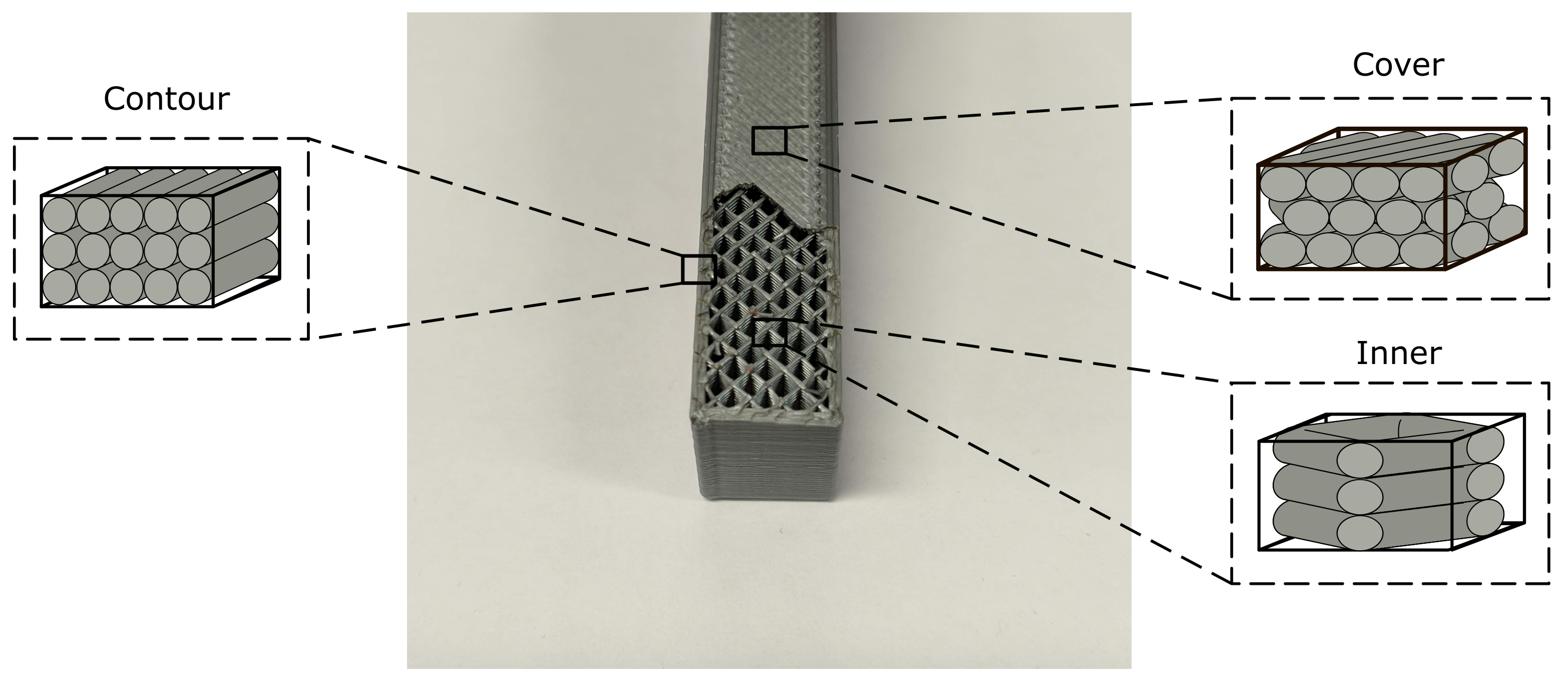
2. Material Characterization
3. Experimental Procedure
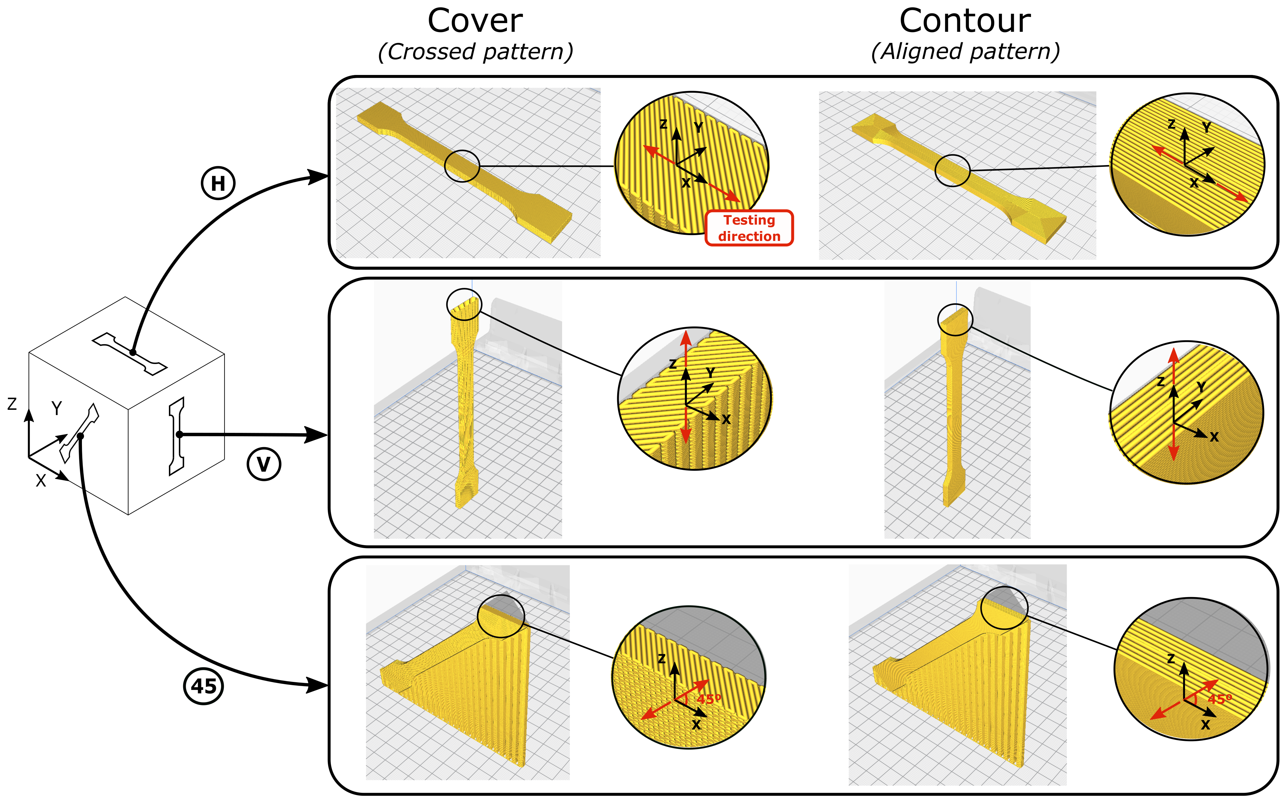
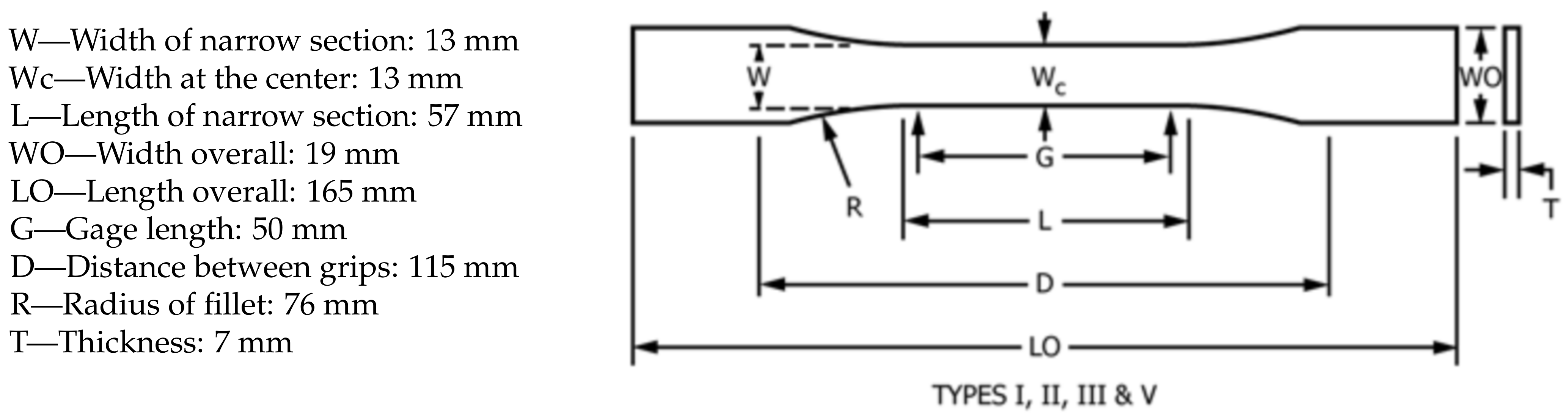
3.1. Uniaxial Tensile Tests
- Young’s modulus in the printing direction was obtained from the V-Cover specimen;
- Young’s modulus in the plane of isotropy was obtained from the H-Cover specimen;
- The shear modulus in the printing direction G was obtained from the 45-Cover specimen with:where 1 is the applied load direction and 2 any direction on its perpendicular plane;
- The shear modulus in the plane of isotropy was obtained with:
- Young’s modulus in the direction parallel to the filament was obtained from the H-Contour specimen;
- Young’s modulus in the plane of isotropy was obtained from the V-Contour specimen;
- The shear modulus in the direction parallel to the filament G was obtained from the 45-Contour specimen with Equation (2);
- The shear modulus in the plane of isotropy was obtained from Equation (3).
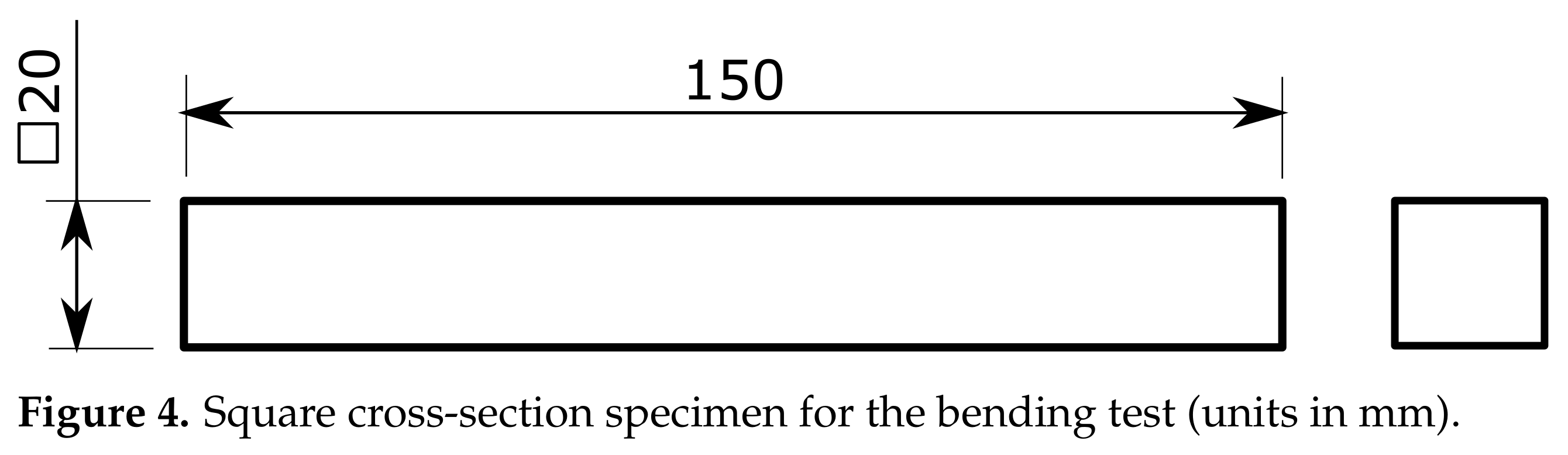
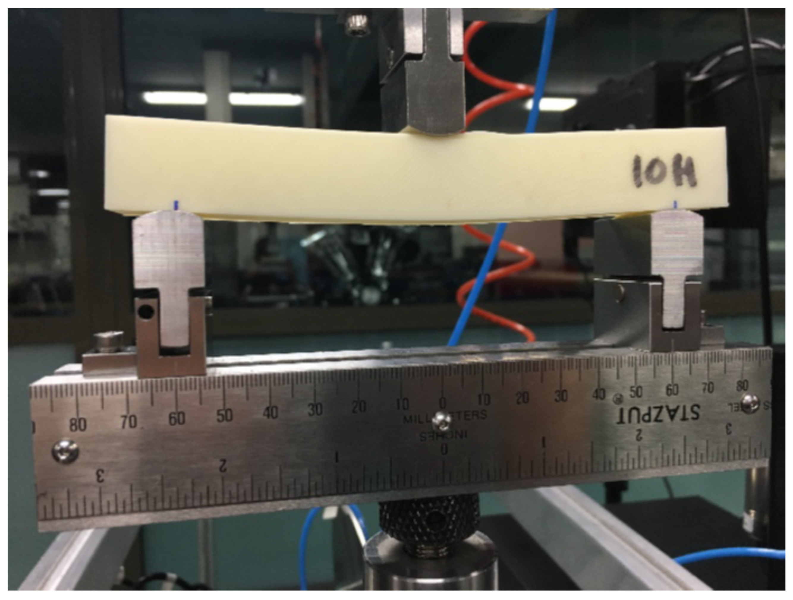
3.2. Bending Tests
4. Computational Characterization
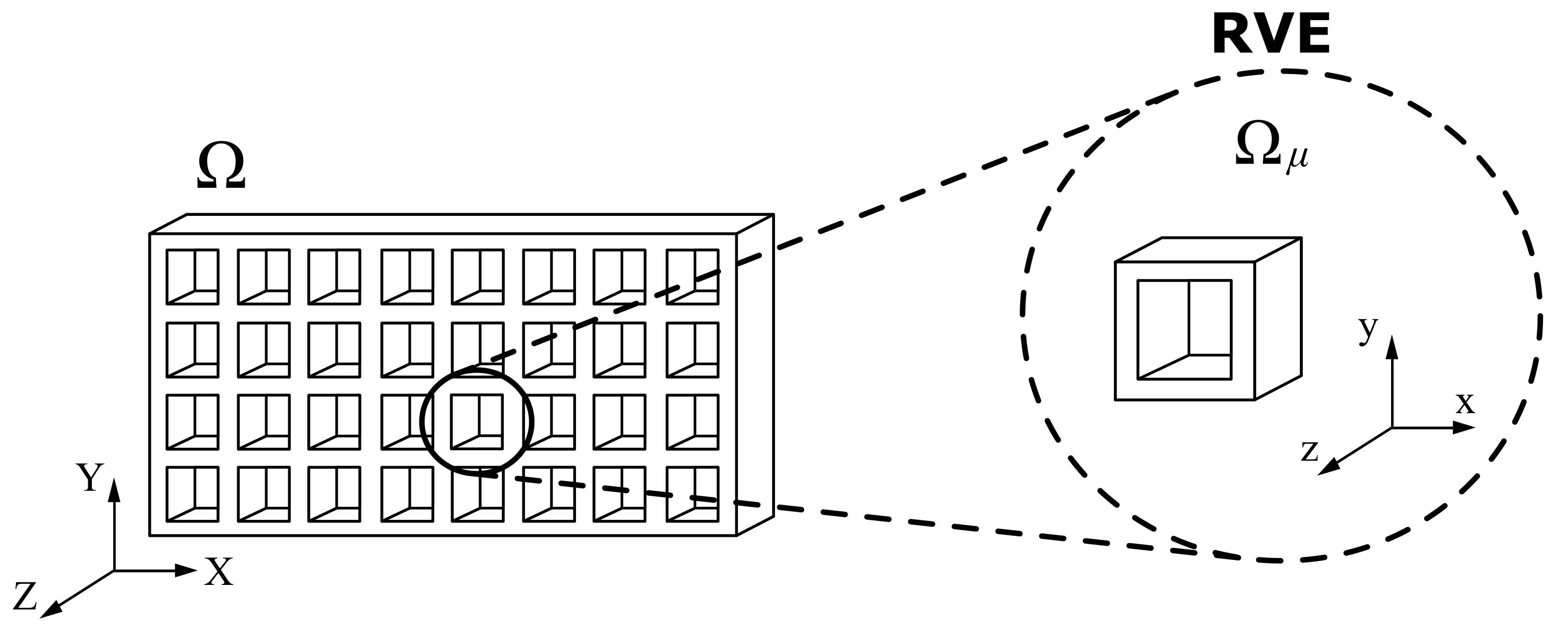
4.1. Representative Volume Element
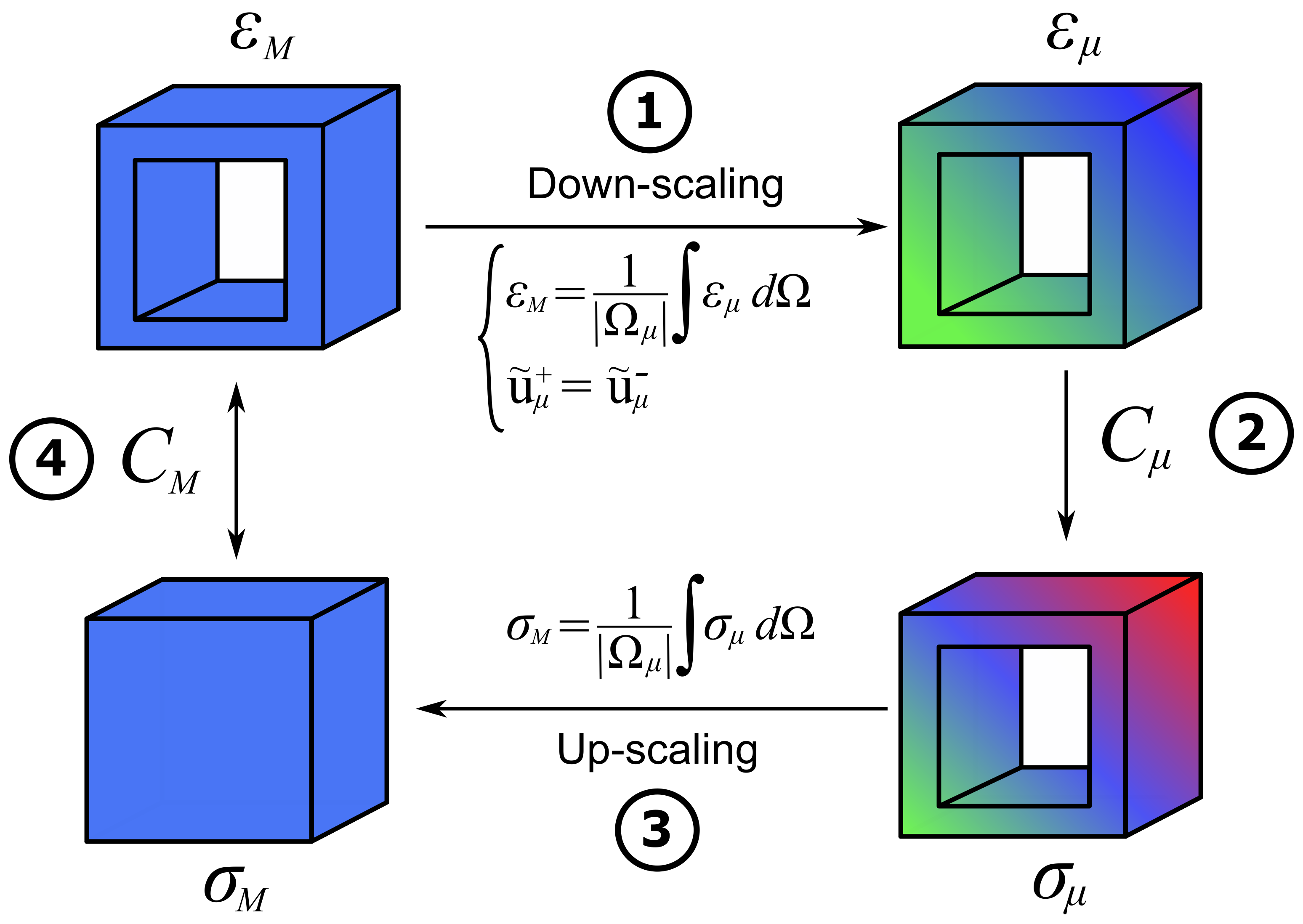
4.2. Multiscale Computational Homogenization
| Algorithm 1: First-order computational homogenization. |
 |
5. Experimental and Computational Results
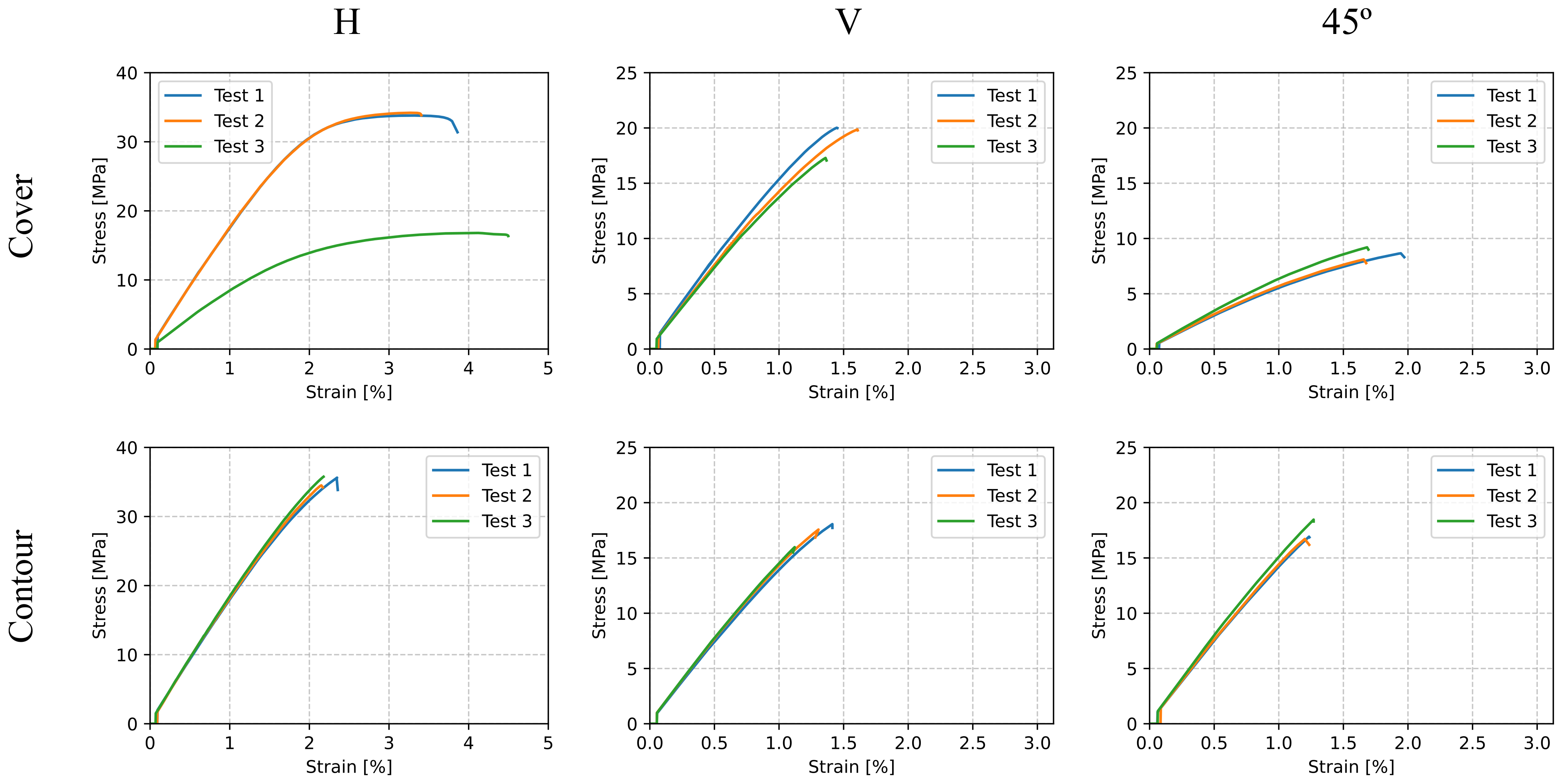
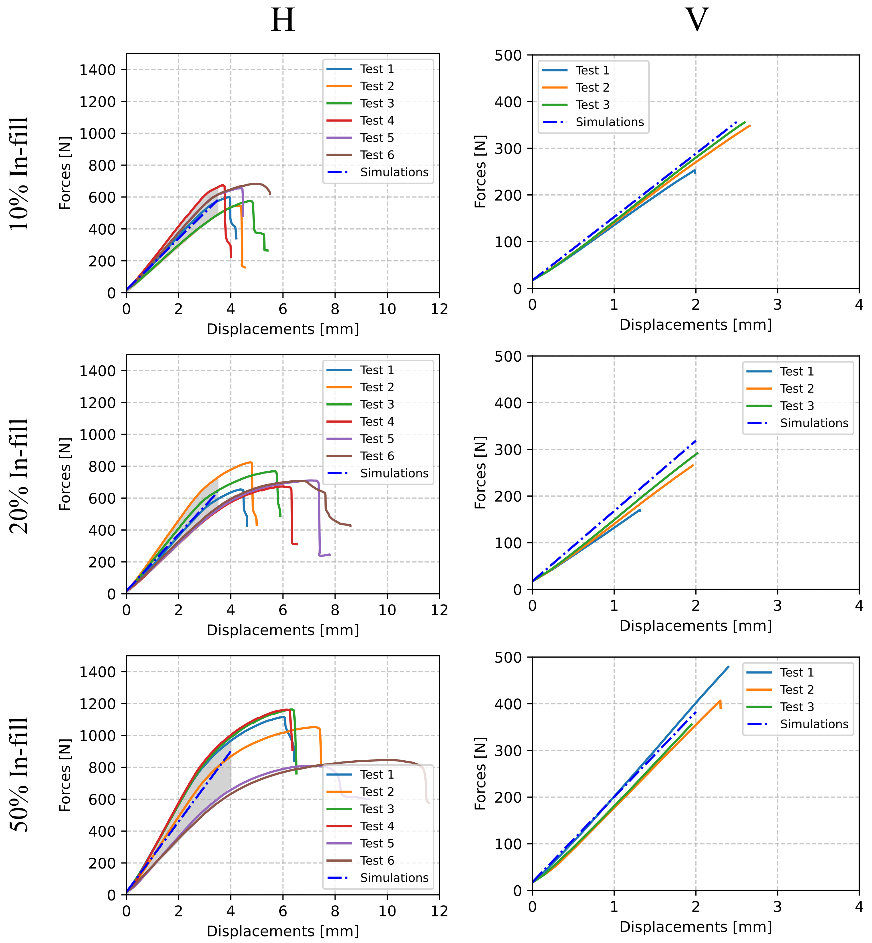
5.1. Tensile Tests
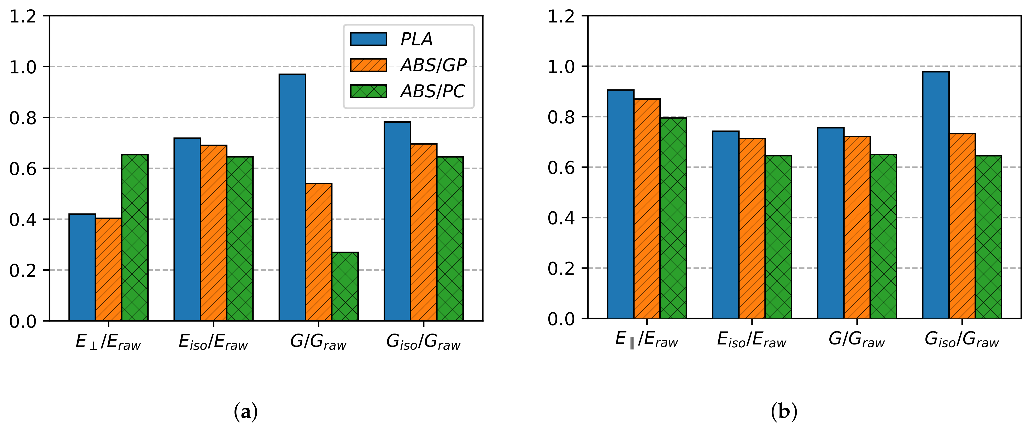
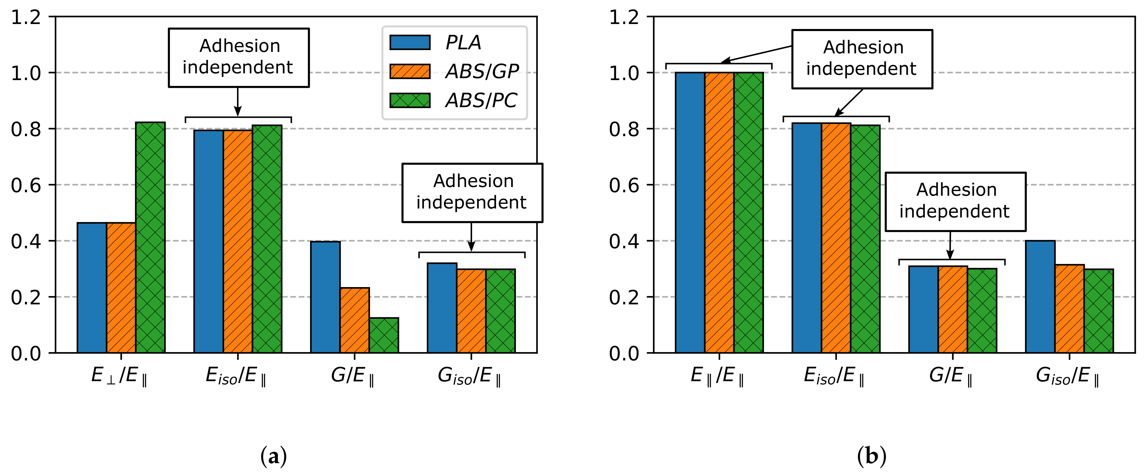
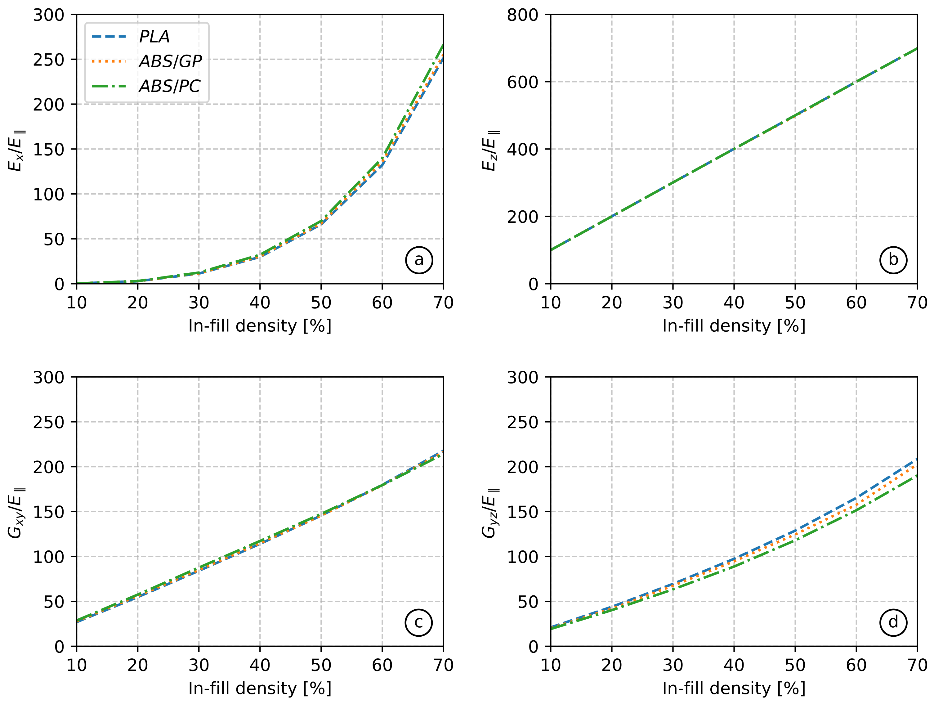
5.2. Homogenization
5.3. Experimental Validation
6. Dimensional Analysis on the Three-Zone Model
7. Conclusions
Author Contributions
Funding
Institutional Review Board Statement
Informed Consent Statement
Data Availability Statement
Conflicts of Interest
Abbreviations
| AM | Additive Manufacturing |
| MJF | Multi-Jet Fusion |
| SLM | Selective Laser Melting |
| EBM | Electron Beam Melting |
| FFF | Fused Filament Fabrication |
| FDM | Fused Deposition Modeling |
| PLA | Polylactic Acid |
| ABS/GP | General Purpose Acrylonitrile Butadiene Styrene |
| ABS/PC | Polycarbonate Acrylonitrile Butadiene Styrene |
| RVE | Representative Volume Element |
| FOCH | First-Order Computational Homogenization |
| BC | Boundary Condition |
| ML | Machine Learning |
References
- Meißner, P.; Watschke, H.; Winter, J.; Vietor, T. Artificial Neural Networks-Based Material Parameter Identification for Numerical Simulations of Additively Manufactured Parts by Material Extrusion. Polymers 2020, 12, 2949. [Google Scholar] [CrossRef] [PubMed]
- Jiang, J.; Xiong, Y.; Zhang, Z.; Rosen, D. Machine learning integrated design for additive manufacturing. J. Intell. Manuf. 2020. [Google Scholar] [CrossRef]
- Nath, S.D.; Nilufar, S. An Overview of Additive Manufacturing of Polymers and Associated Composites. Polymers 2020, 12, 2719. [Google Scholar] [CrossRef] [PubMed]
- Sillani, F.; Kleijnen, R.; Vetterli, M.; Schmid, M.; Wegener, K. Selective laser sintering and multi jet fusion: Process-induced modification of the raw materials and analyses of parts performance. Addit. Manuf. 2019, 27, 32–41. [Google Scholar] [CrossRef]
- Frazier, W. Metal Additive Manufacturing: A Review. J. Mater. Eng. Perform. 2014, 23, 1917–1928. [Google Scholar] [CrossRef]
- Murr, L.E.; Gaytan, S.M.; Ramirez, D.A.; Martinez, E.; Hernandez, J.; Amato, K.N.; Shindo, P.W.; Medina, F.R.; Wicker, R.B. Metal Fabrication by Additive Manufacturing Using Laser and Electron Beam Melting Technologies. J. Mater. Sci. Technol. 2012, 28, 1–14. [Google Scholar] [CrossRef]
- Peterson, A. Review of acrylonitrile butadiene styrene in fused filament fabrication: A plastics engineering-focused perspective. Addit. Manuf. 2019, 27, 363–371. [Google Scholar] [CrossRef]
- Rajpurohit, S.; Dave, H. Analysis of tensile strength of a fused filament fabricated PLA part using an open-source 3D printer. Int. J. Adv. Manuf. Technol. 2019, 101, 1525–1536. [Google Scholar] [CrossRef]
- Bikas, H.; Stavropoulos, P.; Chryssolouris, G. Additive manufacturing methods and modelling approaches: A critical review. Int. J. Adv. Manuf. Technol. 2016, 83, 389–405. [Google Scholar] [CrossRef]
- Kuo, C.; Chen, C.; Chang, S. Polishing mechanism for ABS parts fabricated by additive manufacturing. Int. J. Adv. Manuf. Technol. 2017, 91, 1473–1479. [Google Scholar] [CrossRef]
- Morand, L.; Helm, D. A mixture of experts approach to handle ambiguities in parameter identification problems in material modeling. Comput. Mater. Sci. 2019, 167, 85–91. [Google Scholar] [CrossRef]
- Mohamed, O.; Masood, S.; Bhowmik, J. Optimization of fused deposition modeling process parameters: A review of current research and future prospects. Adv. Manuf. 2015, 3, 42–53. [Google Scholar] [CrossRef]
- Li, L.; McGuan, R.; Isaac, R.; Kavehpour, P.; Candler, R. Improving precision of material extrusion 3D printing by in-situ monitoring & predicting 3D geometric deviation using conditional adversarial networks. Addit. Manuf. 2021, 38, 101695. [Google Scholar] [CrossRef]
- Teraiya, S.; Vyavahare, S.; Kumar, S. Experimental Investigation on Influence of Process Parameters on Mechanical Properties of PETG Parts Made by Fused Deposition Modeling. In Advances in Manufacturing Processes; Dave, H.K., Nedelcu, D., Eds.; Springer: Singapore, 2021; pp. 283–293. [Google Scholar] [CrossRef]
- Chandravadia, M.; Chudasama, M. Experimental Investigation on Tensile Properties of Nylon Glass Fibre Material Made Using Fused Deposition Modeling Process. In Advances in Manufacturing Processes; Dave, H., Nedelcu, D., Eds.; Springer: Singapore, 2021; pp. 329–342. [Google Scholar] [CrossRef]
- Gebisa, A.; Lemu, H. Investigating Effects of Fused-Deposition Modeling (FDM) Processing Parameters on Flexural Properties of ULTEM 9085 using Designed Experiment. Materials 2018, 11, 500. [Google Scholar] [CrossRef]
- Arif, M.; Kumar, S.; Varadarajan, K.; Cantwell, W. Performance of biocompatible PEEK processed by fused deposition additive manufacturing. Mater. Des. 2018, 146, 249–259. [Google Scholar] [CrossRef]
- Cantrell, J.T.; Rohde, S.; Damiani, D.; Gurnani, R.; DiSandro, L.; Anton, J.; Young, A.; Jerez, A.; Steinbach, D.; Kroese, C.; et al. Experimental Characterization of the Mechanical Properties of 3D Printed ABS and Polycarbonate Parts. In Advancement of Optical Methods in Experimental Mechanics; Yoshida, S., Lamberti, L., Sciammarella, C., Eds.; Springer International Publishing: Cham, Switzerland, 2017; Volume 3, pp. 89–105. [Google Scholar] [CrossRef]
- Chockalingam, K.; Jawahar, N.; Praveen, J. Enhancement of Anisotropic Strength of Fused Deposited ABS Parts by Genetic Algorithm. Mater. Manuf. Process. 2016, 31, 2001–2010. [Google Scholar] [CrossRef]
- Carneiro, O.; Silva, A.; Gomes, R. Fused deposition modeling with polypropylene. Mater. Des. 2015, 83, 768–776. [Google Scholar] [CrossRef]
- Croccolo, D.; De Agostinis, M.; Olmi, G. Experimental characterization and analytical modelling of the mechanical behavior of fused deposition processed parts made of ABS-M30. Comput. Mater. Sci. 2013, 79, 506–518. [Google Scholar] [CrossRef]
- Sood, A.; Ohdar, R.; Mahapatra, S. Experimental investigation and empirical modelling of FDM process for compressive strength improvement. J. Adv. Res. 2012, 3, 81–90. [Google Scholar] [CrossRef]
- Liu, C.; Chen, Y.; Yang, S. Quantification of hyperelastic material parameters for a 3D-Printed thermoplastic elastomer with different infill percentages. Mater. Today Commun. 2021, 26, 101895. [Google Scholar] [CrossRef]
- Forés-Garriga, A.; Pérez, M.; Gómez-Gras, G.; Reyes-Pozo, G. Role of infill parameters on the mechanical performance and weight reduction of PEI Ultem processed by FFF. Mater. Des. 2020, 193, 108810. [Google Scholar] [CrossRef]
- Srinivasan, R.; Pridhar, T.; Ramprasath, L.; Charan, N.S.; Ruban, W. Prediction of tensile strength in FDM printed ABS parts using response surface methodology (RSM). Mater. Today Proc. 2020, 27, 1827–1832. [Google Scholar] [CrossRef]
- Zhou, Y.G.; Zou, J.R.; Wu, H.H.; Xu, B.P. Balance between bonding and deposition during fused deposition modeling of polycarbonate and acrylonitrile-butadiene-styrene composites. Polym. Compos. 2020, 41, 60–72. [Google Scholar] [CrossRef]
- Coogan, T.; Kazmer, D. Modeling of interlayer contact and contact pressure during fused filament fabrication. J. Rheol. 2019, 63, 655–672. [Google Scholar] [CrossRef]
- Gilmer, E.L.; Miller, D.; Chatham, C.A.; Zawaski, C.; Fallon, J.J.; Pekkanen, A.; Long, T.E.; Williams, C.B.; Bortner, M.J. Model analysis of feedstock behavior in fused filament fabrication: Enabling rapid materials screening. Polymer 2018, 152, 51–61. [Google Scholar] [CrossRef]
- Phan, D.D.; Swain, Z.R.; Mackay, M.E. Rheological and heat transfer effects in fused filament fabrication. J. Rheol. 2018, 62, 1097–1107. [Google Scholar] [CrossRef]
- McIlroy, C.; Olmsted, P.D. Deformation of an amorphous polymer during the fused-filament-fabrication method for additive manufacturing. J. Rheol. 2017, 61, 379–397. [Google Scholar] [CrossRef]
- Mackay, M.E. The importance of rheological behavior in the additive manufacturing technique material extrusion. J. Rheol. 2018, 62, 1549–1561. [Google Scholar] [CrossRef]
- Dialami, N.; Chiumenti, M.; Cervera, M.; Rossi, R.; Chasco, U.; Domingo, M. Numerical and experimental analysis of the structural performance of AM components built by Fused Filament Fabrication. Int. J. Mech. Mater. Des. 2020. [Google Scholar] [CrossRef]
- Dialami, N.; Chiumenti, M.; Cervera, M.; Chasco, U.; Reyes-Pozo, G.; Pérez, M.A. Printing pattern based material characterization and enhanced performance analysis of FFF components: Experimental and computational validation. Comput. Struct. 2021. submitted. [Google Scholar]
- Çengel, Y.; Cimbala, J. Mecánica de Fluidos. In Fundamentos y Aplicaciones; McGraw-Hill Interamericana: Mexico City, Mexico, 2006. [Google Scholar]
- Yang, F.; Pitchumani, R. Healing of thermoplastic polymers at an interface under nonisothermal conditions. Macromolecules 2002, 35, 3213–3224. [Google Scholar] [CrossRef]
- Bartolai, J.; Simpson, T.W.; Xie, R. Predicting strength of additively manufactured thermoplastic polymer parts produced using material extrusion. Rapid Prototyp. J. 2018, 24, 321–332. [Google Scholar] [CrossRef]
- Ma, Q.; Zhao, W.; Li, X.; Li, L.; Wang, Z. Study of an environment-friendly surface pretreatment of ABS-polycarbonate surface for adhesion improvement. Int. J. Adhes. Adhes. 2013, 44, 243–249. [Google Scholar] [CrossRef]
- ELIX Polimers. ELIX PC/ABS 5130 Technical Information. 2020. Available online: https://www.elix-polymers.com/uploads/ELIX%20Polymers%20-%20ELIX%20PC-ABS%205130%20-%20ASTM%20 (accessed on 12 February 2021).
- Bierögel, C.; Grellmann, W. Quasi-Static Tensile Test—Poisson Ratio of Thermoplastic Materials—Data; Springer: Berlin/Heidelberg, Germany, 2014. [Google Scholar] [CrossRef]
- Ashby, M.F.; Jones, D. Engineering Materials 2: An Introduction to Microstructures, Processing, and Design; Pergamon Press: Oxford, UK, 1986. [Google Scholar]
- Casavola, C.; Cazzato, A.; Moramarco, V.; Pappalettere, C. Orthotropic mechanical properties of fused deposition modelling parts described by classical laminate theory. Mater. Des. 2016, 90, 453–458. [Google Scholar] [CrossRef]
- ASTM Standards. Standard Test Method for Tensile Properties of Plastics; American Society for Testing and Materials: Conshohocken, PA, USA, 1958. [Google Scholar]
- American Society for Testing and Materials. ASTM D790-07. In Standard Test Methods for Flexural Properties of Unreinforced and Reinforced Plastics and Electrical Insulating Materials; American Society for Testing and Materials: Conshohocken, PA, USA, 2007. [Google Scholar]
- Zhang, Y.; Li, F.; Jia, D. Lattice impeller design and multi-scale stress-deformation analysis based on conventional cubic lattice. Mech. Adv. Mater. Struct. 2020, 1–17. [Google Scholar] [CrossRef]
- Hassani, B.; Hinton, E. A review of homogenization and topology optimization I—homogenization theory for media with periodic structure. Comput. Struct. 1998, 69, 707–717. [Google Scholar] [CrossRef]
- Feyel, F.; Chaboche, J. FE2 multiscale approach for modelling the elastoviscoplastic behavior of long fibre SiC/Ti composite materials. Comput. Methods Appl. Mech. Eng. 2000, 183, 309–330. [Google Scholar] [CrossRef]
- Feyel, F. A multilevel finite element method (FE2) to describe the response of highly non-linear structures using generalized continua. Comput. Methods Appl. Mech. Eng. 2003, 192, 3233–3244. [Google Scholar] [CrossRef]
- McDowell, D. A perspective on trends in multiscale plasticity. Int. J. Plast. 2010, 26, 1280–1309. [Google Scholar] [CrossRef]
- Nguyen, V.P.; Stroeven, M.; Sluys, L. Multiscale continuous and discontinuous modeling of heterogeneous materials: A review on recent developments. J. Multiscale Model. 2011, 3, 229–270. [Google Scholar] [CrossRef]
- Efendiev, Y.; Galvis, J.; Hou, T. Generalized multiscale finite element methods (GMsFEM). J. Comput. Phys. 2013, 251, 116–135. [Google Scholar] [CrossRef]
- Lloberas-Valls, O.; Raschi, M.; Huespe, A.; Oliver, J. Reduced finite element square techniques (rfe 2): Towards industrial multiscale fe software. In Proceedings of the XV International Conference on Computational Plasticity, Fundamentals and Applications, COMPLAS 2019, Barcelona, Spain, 3–5 September 2019. [Google Scholar]
- Caicedo, M.; Mroginski, J.; Toro, S.; Raschi, M.; Huespe, A.; Oliver, J. High Performance Reduced Order Modeling Techniques Based on Optimal Energy Quadrature: Application to Geometrically Non-linear Multiscale Inelastic Material Modeling. Arch. Comput. Methods Eng. 2019, 26, 771–792. [Google Scholar] [CrossRef]
- Raschi, M.; Lloberas-Valls, O.; Huespe, A.; Oliver, J. High performance reduction technique for multiscale finite element modeling (HPR-FE2): Towards industrial multiscale FE software. Comput. Methods Appl. Mech. Eng. 2021, 375, 113580. [Google Scholar] [CrossRef]
- Dadvand, P.; Rossi, R.; Oñate, E. An Object-oriented Environment for Developing Finite Element Codes for Multi-disciplinary Applications. Arch. Comput. Methods Eng. 2010, 17, 253–297. [Google Scholar] [CrossRef]
- Cervera, M.; Agelet de Saracibar, C. COMET: Coupled Mechanical and Thermal Analysis, Data Input Manual, Version 5.0, Technical Report IT-308. 2002. Available online: http://www.cimne.upc.es (accessed on 25 February 2021).
- Wu, W.; Ye, W.; Geng, P.; Wang, Y.; Li, G.; Hu, X.; Zhao, J. 3D printing of thermoplastic PI and interlayer bonding evaluation. Mater. Lett. 2018, 229, 206–209. [Google Scholar] [CrossRef]
- Lepoivre, A.; Boyard, N.; Levy, A.; Sobotka, V. Heat transfer and adhesion study for the FFF additive manufacturing process. Procedia Manuf. 2020, 47, 948–955. [Google Scholar] [CrossRef]
- Coogan, T.; Kazmer, D. Prediction of interlayer strength in material extrusion additive manufacturing. Addit. Manuf. 2020, 35. [Google Scholar] [CrossRef]
- Baturynska, I.; Semeniuta, O.; Martinsen, K. Optimization of Process Parameters for Powder Bed Fusion Additive Manufacturing by Combination of Machine Learning and Finite Element Method: A Conceptual Framework. Procedia CIRP 2018, 67, 227–232. [Google Scholar] [CrossRef]
- Wang, C.; Tan, X.; Tor, S.; Lim, C. Machine learning in additive manufacturing: State-of-the-art and perspectives. Addit. Manuf. 2020, 36. [Google Scholar] [CrossRef]


| Cover | G | G | |||||||
| Contour | G | G |
| Printing Parameter | Value |
|---|---|
| Extrusion temperature (°C) | 250 |
| Base temperature (°C) | 95 |
| Layer thickness (mm) | 0.15 |
| First layer printing speed (mm/s) | 15 |
| Contour printing speed (mm/s) | 18 |
| Cover printing speed (mm/s) | 20 |
| Inner printing speed (mm/s) | 25 |
| Material Properties | Cover | Contour |
|---|---|---|
| (GPa) (GPa) | 1.53 ± 0.09 | 1.86 ± 0.04 |
| (GPa) | 1.51 ± 0.5 | 1.51 ± 0.03 |
| 0.36 ± 0.01 | 0.36 ± 0.01 | |
| 0.36 ± 0.01 | 0.36 ± 0.01 | |
| G (GPa) | 0.232 ± 0.02 | 0.559 ± 0.02 |
| (GPa) | 0.555 ± 0.2 | 0.555 ± 0.01 |
| In-Fill (%) | 10 | 20 | 50 |
|---|---|---|---|
| (MPa) | 0.61 | 5.47 | 129.99 |
| (MPa) | 0.61 | 5.47 | 130.02 |
| (MPa) | 186.00 | 372.00 | 930.00 |
| 0.99 | 0.9739 | 0.8022 | |
| 0.3528 | 0.3530 | 0.3530 | |
| 0.3532 | 0.3530 | 0.3530 | |
| (MPa) | 53.33 | 106.98 | 274.11 |
| (MPa) | 35.84 | 74.83 | 219.43 |
| (MPa) | 35.84 | 74.83 | 219.43 |
| In-Fill Density (%) | Printing Orientation | Relative Difference (%) | ||
|---|---|---|---|---|
| 10 | H | 174.33 | 161.18 | 7.54 |
| V | 139.10 | 135.77 | 2.39 | |
| 20 | H | 179.26 | 177.13 | 1.19 |
| V | 139.61 | 150.49 | 7.79 | |
| 50 | H | 223.25 | 220.67 | 1.16 |
| V | 186.38 | 182.46 | 2.10 |
| ASTM | Orientation | Pattern | Nomenclature | Characterized Property |
|---|---|---|---|---|
| ASTM D638 | Horizontal | Crossed (cover) | H-Cover | , |
| Aligned (contour) | H-Contour | |||
| Vertical | Crossed (cover) | V-Cover | ||
| Aligned (contour) | V-Contour | , | ||
| 45° | Crossed (cover) | 45-Cover | ||
| Aligned (contour) | 45-Contour | |||
| ASTM D790 | Horizontal | In-fill 10% | H-10 | |
| In-fill 20% | H-20 | |||
| In-fill 50% | H-50 | |||
| Vertical | In-fill 10% | V-10 | ||
| In-fill 20% | V-20 | |||
| In-fill 50% | V-50 |
| Property | Value |
|---|---|
| 0.80 | |
| 0.30 | |
| 0.87 | |
| 0.82 | |
| 0.31 |
Publisher’s Note: MDPI stays neutral with regard to jurisdictional claims in published maps and institutional affiliations. |
© 2021 by the authors. Licensee MDPI, Basel, Switzerland. This article is an open access article distributed under the terms and conditions of the Creative Commons Attribution (CC BY) license (https://creativecommons.org/licenses/by/4.0/).
Share and Cite
Rivet, I.; Dialami, N.; Cervera, M.; Chiumenti, M.; Reyes, G.; Pérez, M.A. Experimental, Computational, and Dimensional Analysis of the Mechanical Performance of Fused Filament Fabrication Parts. Polymers 2021, 13, 1766. https://doi.org/10.3390/polym13111766
Rivet I, Dialami N, Cervera M, Chiumenti M, Reyes G, Pérez MA. Experimental, Computational, and Dimensional Analysis of the Mechanical Performance of Fused Filament Fabrication Parts. Polymers. 2021; 13(11):1766. https://doi.org/10.3390/polym13111766
Chicago/Turabian StyleRivet, Iván, Narges Dialami, Miguel Cervera, Michele Chiumenti, Guillermo Reyes, and Marco A. Pérez. 2021. "Experimental, Computational, and Dimensional Analysis of the Mechanical Performance of Fused Filament Fabrication Parts" Polymers 13, no. 11: 1766. https://doi.org/10.3390/polym13111766
APA StyleRivet, I., Dialami, N., Cervera, M., Chiumenti, M., Reyes, G., & Pérez, M. A. (2021). Experimental, Computational, and Dimensional Analysis of the Mechanical Performance of Fused Filament Fabrication Parts. Polymers, 13(11), 1766. https://doi.org/10.3390/polym13111766